EP0789129A2 - Mouton de forage autopropulsé - Google Patents
Mouton de forage autopropulsé Download PDFInfo
- Publication number
- EP0789129A2 EP0789129A2 EP96113139A EP96113139A EP0789129A2 EP 0789129 A2 EP0789129 A2 EP 0789129A2 EP 96113139 A EP96113139 A EP 96113139A EP 96113139 A EP96113139 A EP 96113139A EP 0789129 A2 EP0789129 A2 EP 0789129A2
- Authority
- EP
- European Patent Office
- Prior art keywords
- control
- boring machine
- machine according
- ram boring
- control sleeve
- Prior art date
- Legal status (The legal status is an assumption and is not a legal conclusion. Google has not performed a legal analysis and makes no representation as to the accuracy of the status listed.)
- Granted
Links
Images


Classifications
-
- E—FIXED CONSTRUCTIONS
- E21—EARTH OR ROCK DRILLING; MINING
- E21B—EARTH OR ROCK DRILLING; OBTAINING OIL, GAS, WATER, SOLUBLE OR MELTABLE MATERIALS OR A SLURRY OF MINERALS FROM WELLS
- E21B4/00—Drives for drilling, used in the borehole
- E21B4/06—Down-hole impacting means, e.g. hammers
- E21B4/14—Fluid operated hammers
- E21B4/145—Fluid operated hammers of the self propelled-type, e.g. with a reverse mode to retract the device from the hole
Definitions
- ram boring machines For drilling holes in the ground or for the destructive replacement of buried pipelines, ram boring machines with a reciprocating percussion piston arranged in the device are used.
- Ram drilling rigs of this type have proven themselves extremely well for trenchless laying of lines in the ground or for the destructive replacement of underground pipes; they need to be reversed in order, for example, to be able to produce blind bores or not to have to dig out a device stopped by an insurmountable ground obstacle, but rather to be able to move it backwards out of the earth borehole that it has already created.
- European Patent Specification 0 484 839 describes a ram boring machine with a stepped tube which projects into a rear working space of the percussion piston and on which a control sleeve is mounted so as to be axially adjustable.
- the percussion piston with its jacket surrounding the rear working space is axially guided between the control sleeve and the housing wall.
- control sleeve Inside the control sleeve there is a return spring between a stop of the stepped tube for the supply of working air on the one hand and a collar of the control sleeve on the other hand, which in cooperation with control air supplied via an axially parallel channel, the control sleeve in its forward position against the pressure of the working air in the working space of the percussion piston holds.
- a disadvantage of this reversal is the fact that the percussion piston is guided directly on the control sleeve and that the return spring is inside the control sleeve, the smallest diameter of which is therefore determined by the diameter of the return spring. This places a corresponding lower limit on the outer diameter of the ram boring machine.
- Another problem arises when the spring breaks in the return position, which can easily be the case with the strong dynamic load and the small space, it is no longer possible to switch to the forward position via the compressed air. On the other hand, if the spring breaks in the forward position, the forward automatically switches to the return without this being prevented from the outside.
- the axially movable control sleeve also has constant sliding contact with the inner wall of the piston. In the event of increased friction, such as occurs due to contamination or if lubrication is not optimal, the control sleeve can move back and forth, since the low reversing forces are insufficient to fix the sleeve axially. The same problem occurs when a self-propelled Ram drill tensed or bent when passing through different soil layers in the ground.
- control channel consists of two concentric tubes, which means that radially more space is required than if the control air is supplied through one or more radial bores. This is a major disadvantage, especially with smaller units, since there is hardly any space for exhaust air and supply air ducts.
- the invention lies inter alia. the problem is based, in particular to avoid the disadvantages that result from the fact that the control sleeve and the casing of the percussion piston working space are in direct contact with one another.
- the invention proposes a ram boring machine in which a housing-fixed compressed air-guiding tube is immersed in the rear working space of the percussion piston, on which the jacket of the rear percussion piston working space is guided. Accordingly, the percussion piston is mounted on a part fixed to the housing in the region of its rear working space.
- the control slide in the form of an axially adjustable control sleeve is axially adjustable in an annular space of the guide tube, which preferably consists of an inner and an outer tube. This interior and the control sleeve can be provided with corresponding stops which determine at least one of the two working positions of the control sleeve.
- the inner tube, the outer tube and the control sleeve can be provided with radial control openings which correspond in groups to one another in the case of flow or return.
- control sleeve In order to move the control sleeve into one of its two working positions or to hold it there, the control sleeve can be under the influence of a compression spring and / or a control air line in the form of a control air duct can open into the annular space in front of the control sleeve. If the directions of action of the compression spring and the control air are opposite to each other, then the control sleeve can be adjusted with the aid of the control air against the compression spring, which then works as a return spring for the control sleeve when the control air is no longer effective.
- control air and the spring can also have the same direction of action.
- the control air channel opens into a pressure chamber of the control sleeve and the control sleeve is adjusted with the help of the control air and the compression spring on the one hand and with the help of the working air entering another pressure chamber of the control sleeve.
- control air line runs through the guide tube 8
- the working air or compressed air for the percussion piston is effective instead of the control air.
- the control sleeve is in its return position under the influence of the control air, then the working air holds the control sleeve in this position in the event of a leak. Is the control air line is depressurized and the control sleeve is in its forward position, then the working air automatically pushes the control sleeve into its return position in the event of a leak and the device moves out of the ground.
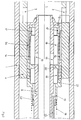
- the ram boring machine consists of a cylindrical housing 1 with a striking tip 2 and a striking piston 4 provided with radial control openings 3, in the rear part of which there is a rear working space 5.
- a stop ring 6 with axially parallel ventilation openings 7 is installed in the rear part of the housing 1.
- the stop ring 6 extends through a guide tube 8 which is connected on the one hand to a working or compressed air hose (not shown) and on the other hand dips with its front end into the working space 5 of the percussion piston 4.
- the guide tube 8 consists of an inner tube 9 and a shorter outer tube 10, between which there is an annular space 11 with a bore 12 opening into the working space 5, for example an end bore.
- the inner tube 9 has one or more radial control openings 13 and the outer tube has radial control openings 14.
- An axially adjustable control sleeve 15 is guided in the annular space 11, between which and a stop on the inner tube 9 a compression spring 16 extends.
- the control sleeve 15 has radial control openings 17 and a front, via the control opening 13 with the Compressed air-carrying inner tube 9 communicating pressure chamber 18 and a pressure chamber 19 which is connected to a control air source via a control air line in the form of a control air channel 20 in the inner tube wall and a valve, not shown. Furthermore, the control sleeve has a stop edge 21 and an inside stop collar 22, while the inner tube 9 is provided with a stop collar 23.
- the outer tube is further provided with an outer recess 24.
- the rear pressure chamber 19 of the control sleeve 15 is vented and moves the air through the bore 12 in front of the control sleeve and the compressed air present in the front pressure chamber 18 and in the working space 5, the control sleeve 15 against the force of the compression spring 16 into the return position (FIG. 3).
- the radial control openings 13, 14, 17 of the inner and outer tubes 9, 10 and the control bushing 15 are aligned, with the result that compressed air also reaches the front working space via these control openings when the radial control openings 3 of the Percussion piston 4 are in the region of the recess 24.
- the percussion piston end face is pressurized with compressed air until finally its control openings 3 pass over the stop edge 21 and the compressed air can flow out of the front working space via the annular space surrounding the guide tube 8 behind the control sleeve and the ventilation holes 7 and the percussion piston with its rear end face onto the Stop ring 6 hits to deliver its impact energy here.
- control air passes through the channel 20 into the pressure chamber 19 of the control sleeve 15, it moves under the influence of the compression spring 16 and the control air against the action of the compressed air present in the front pressure chamber 18 and through the end bore 12 in the annular space 11 in front of the control sleeve in the direction of advance until the stop edge 21 hits the outer tube 10 and the forward position (FIG. 2) is reached.
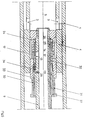
- a control air duct 25 with an outlet opening 26 extends into in the reversing according to FIGS. 4, 5 a pressure chamber 35 located in front of a control slide 27 in the front part of the annular space 11 and the inner tube 9 is provided with a radial bore 28 and a collar 29 acting as a stop.
- the outer tube has an additional recess 30 with radial control openings 31, while the control bushing 27 is provided with an inward-facing stop ring 32 and additional rear control openings 33 which open into the rear part of the annular space 11.
- the pressure chamber 35 is vented in the part of the annular space 11 located in front of the control bushing via the control air duct 25, so that the force of the operating compressed air which flows through the opening 28 into a pressure chamber 34 reached, is sufficient to bring the control sleeve into the return position (Fig. 5).
- the control openings 13, 14, 17 are aligned in the inner and outer tubes 9, 10 and in the control sleeve 27, so that the working space in front of the percussion piston 4 - as described in connection with FIGS. 1 to 3 - continues to be supplied with compressed air when the control openings 3 of the percussion piston 4 reach the area of the front recess 24 of the outer tube 10.
- the radial bore 28 serves to continuously supply the pressure chamber 34 with the operating compressed air of the ram boring machine.
- the pressure chamber 35 has the effect that, if the control air channel 25 is vented, the control slide 27 is pushed into the return position.
- the effective surface area under pressure in the chamber 34 is smaller than that of the chamber 35, which only makes it possible to move it. This reversal works purely pneumatically without a compression spring 16.
- the two exemplary embodiments differ from one another in that, in the exemplary embodiment of FIGS. 1 to 3, the control air and the compression spring 23 act in the same direction and accordingly the control sleeve 15 during the advance in its forward position (FIGS. 1, 2) and during the return is in its rearward position (Fig. 3).
- the control air in the embodiment of FIGS. 4, 5 acts opposite to the direction of travel of the ram boring machine, so that the control sleeve 27 is in its rearward position (FIG. 4) during the advance and in its forward position during the return (FIG. 5) is located.
- the reversal of movement of the ram boring machine is brought about by actuating a control air valve and moving a control sleeve encapsulated with respect to the percussion piston from one working position to the other.
- FIGS. 6 and 7 differs from the reversal of FIGS. 5 and 6 in that the control air reaches the pressure chamber 35 through a control air hose 36 running in the inner tube 9. Furthermore, the control sleeve 37 has only front control openings 17, while the control sleeve 27 has front control openings 17 and rear control openings 33. The omission of the rear control openings 33 leads to the control bush 37 being in the rear (FIG. 6) during reverse travel and in the front working position during FIG. 6 (FIG. 7). Since there is a leak in the control air hose 36 under the influence of the working or compressed air in the inner tube 9, the control sleeve 37 always moves into its return position in the event of a leak.
Landscapes
- Engineering & Computer Science (AREA)
- Life Sciences & Earth Sciences (AREA)
- Geology (AREA)
- Mining & Mineral Resources (AREA)
- Mechanical Engineering (AREA)
- Physics & Mathematics (AREA)
- Environmental & Geological Engineering (AREA)
- Fluid Mechanics (AREA)
- General Life Sciences & Earth Sciences (AREA)
- Geochemistry & Mineralogy (AREA)
- Earth Drilling (AREA)
- Drilling And Exploitation, And Mining Machines And Methods (AREA)
Applications Claiming Priority (2)
| Application Number | Priority Date | Filing Date | Title |
|---|---|---|---|
| DE19530972 | 1995-08-23 | ||
| DE19530972A DE19530972C2 (de) | 1995-08-23 | 1995-08-23 | Selbstgetriebenes Rammbohrgerät |
Publications (3)
| Publication Number | Publication Date |
|---|---|
| EP0789129A2 true EP0789129A2 (fr) | 1997-08-13 |
| EP0789129A3 EP0789129A3 (fr) | 1999-07-14 |
| EP0789129B1 EP0789129B1 (fr) | 2002-11-13 |
Family
ID=7770163
Family Applications (1)
| Application Number | Title | Priority Date | Filing Date |
|---|---|---|---|
| EP96113139A Expired - Lifetime EP0789129B1 (fr) | 1995-08-23 | 1996-08-16 | Mouton de forage autopropulsé |
Country Status (5)
| Country | Link |
|---|---|
| US (1) | US5960892A (fr) |
| EP (1) | EP0789129B1 (fr) |
| JP (1) | JPH09165986A (fr) |
| AT (1) | ATE227803T1 (fr) |
| DE (2) | DE19530972C2 (fr) |
Families Citing this family (10)
| Publication number | Priority date | Publication date | Assignee | Title |
|---|---|---|---|---|
| DE19858519C2 (de) * | 1998-12-18 | 2002-08-29 | Tracto Technik | Pneumatisch umsteuerbares Rammbohrgerät |
| DE19904864C2 (de) * | 1999-02-06 | 2001-02-22 | Tracto Technik | Verwendung eines Druckluftschlauchs |
| DE29912676U1 (de) | 1999-07-21 | 1999-09-16 | Tracto-Technik Paul Schmidt Spezialmaschinen, 57368 Lennestadt | Schneidkopf |
| DE10146023B4 (de) * | 2001-09-18 | 2006-02-23 | Tracto-Technik Gmbh | Steuerung für einen Schlagantrieb |
| DE10241610B4 (de) * | 2002-08-20 | 2006-08-31 | Tracto-Technik Gmbh | Adapter zum Verbinden einer einzuziehenden Rohrleitung mit einer Zugvorrichtung |
| WO2004018925A1 (fr) | 2002-08-20 | 2004-03-04 | Tracto-Technik Gmbh | Systeme d'assemblage pour l'insertion de canalisations |
| DE102007016823A1 (de) * | 2007-04-05 | 2008-11-06 | Tracto-Technik Gmbh & Co. Kg | Bohrsystem |
| DE102009038383B4 (de) * | 2009-08-24 | 2014-10-16 | Tracto-Technik Gmbh & Co. Kg | Rammbohrvorrichtung |
| DE102015008339A1 (de) * | 2015-07-01 | 2017-01-05 | Tracto-Technik Gmbh & Co. Kg | "Rammbohrvorrichtung und Verfahren zum Umsteuern einer Rammbohrvorrichtung" |
| RU200308U1 (ru) * | 2020-02-27 | 2020-10-16 | ООО Пневмоударная техника | Пневмоударное устройство для проходки скважин в грунте |
Family Cites Families (10)
| Publication number | Priority date | Publication date | Assignee | Title |
|---|---|---|---|---|
| US3744576A (en) * | 1971-02-03 | 1973-07-10 | B Sudnishnikov | Reversible percussion device |
| SU652279A1 (ru) * | 1975-10-01 | 1979-03-15 | Институт Горного Дела Со Ан Ссср | Устройство ударного действи дл образовани скважин в грунте |
| US4171727A (en) * | 1976-10-22 | 1979-10-23 | Institut Gornogo Dela Sibirskogo Otdelenia Akademii Nauk S S S R | Reversible, percussive device for ground perforation |
| AT356592B (de) * | 1978-02-16 | 1980-05-12 | Inst Gornogo Dela Sibirskogo O | Schlagartig wirkende umsteuerbare druckluftein- richtung zur bildung von bohrungen |
| DE2820785C2 (de) * | 1978-05-12 | 1986-10-02 | Paul 5940 Lennestadt Schmidt | Ventilsteuerung für Rammbohrgeräte |
| DE2911837C2 (de) * | 1979-03-26 | 1986-09-11 | Paul 5940 Lennestadt Schmidt | Steuerung für selbstgetriebene Rammbohrgeräte |
| SU1250619A1 (ru) * | 1984-03-06 | 1986-08-15 | Институт Горного Дела Со Ан Ссср | Пневматическое реверсивное устройство дл образовани скважин в грунте |
| GB2165279B (en) * | 1984-10-03 | 1987-12-23 | Inst Gornogo Dela Sibirskogo O | Air-operated reversible percussive action machine |
| DE3807831C1 (fr) * | 1988-03-10 | 1989-05-11 | Schmidt, Paul, 5940 Lennestadt, De | |
| US5172771A (en) * | 1990-11-06 | 1992-12-22 | Charles Machine Works, Inc. | Reversible impact-operated boring tool |
-
1995
- 1995-08-23 DE DE19530972A patent/DE19530972C2/de not_active Expired - Fee Related
-
1996
- 1996-08-16 AT AT96113139T patent/ATE227803T1/de not_active IP Right Cessation
- 1996-08-16 DE DE59609869T patent/DE59609869D1/de not_active Expired - Lifetime
- 1996-08-16 EP EP96113139A patent/EP0789129B1/fr not_active Expired - Lifetime
- 1996-08-23 US US08/697,410 patent/US5960892A/en not_active Expired - Lifetime
- 1996-08-23 JP JP8241034A patent/JPH09165986A/ja not_active Withdrawn
Also Published As
| Publication number | Publication date |
|---|---|
| DE59609869D1 (de) | 2002-12-19 |
| JPH09165986A (ja) | 1997-06-24 |
| EP0789129B1 (fr) | 2002-11-13 |
| DE19530972C2 (de) | 1999-12-02 |
| ATE227803T1 (de) | 2002-11-15 |
| EP0789129A3 (fr) | 1999-07-14 |
| US5960892A (en) | 1999-10-05 |
| DE19530972A1 (de) | 1997-02-27 |
Similar Documents
| Publication | Publication Date | Title |
|---|---|---|
| DE3882953T2 (de) | Rammbohrgerät mit Kontrollventil. | |
| DE2634066C3 (de) | Vorrichtung für den Vor- und Rücklauf von selbstangetriebenen, pneumatischen Rammbohrgeräten | |
| DE3852548T2 (de) | Hydraulische gesteinsbohrmaschine im bohrloch. | |
| DE69912676T2 (de) | Elektromagnetisch betätigte Ventileinheit mit zwei Kolbenschiebern | |
| DE2911837C2 (de) | Steuerung für selbstgetriebene Rammbohrgeräte | |
| DE2443800A1 (de) | Hydraulisch betriebene schlagvorrichtung | |
| CH636407A5 (de) | Ventilsteuerung fuer rammbohrgeraete. | |
| DE19530972C2 (de) | Selbstgetriebenes Rammbohrgerät | |
| DE2754489A1 (de) | Hydraulisch betaetigte schlagvorrichtung | |
| DE19858519C2 (de) | Pneumatisch umsteuerbares Rammbohrgerät | |
| WO2007057055A1 (fr) | Appareil de forage percutant equipe d'un systeme de changement de marche pneumatique | |
| EP0805258B1 (fr) | Mouton de forage réversible | |
| DE19623016C2 (de) | Schlagend arbeitende Vorrichtung | |
| DE2812358A1 (de) | Verfahren zur steuerung der bewegungsumkehr von einrichtungen zur bildung von bohrungen im boden und einrichtung zur durchfuehrung des verfahrens | |
| DE3919656C2 (fr) | ||
| WO2002044508A2 (fr) | Appareil pneumatique de forage de roches et procede de forage horizontal avec air comprime et fluide de forage | |
| EP2470742B1 (fr) | Perforateur à percussion | |
| DE69118885T2 (de) | Bodenverdrängungshammer mit umschaltmechanismus | |
| DE3414775C2 (fr) | ||
| DE4143475C2 (de) | Schlaggerät, insbesondere selbstgetriebenes Rammbohrgerät | |
| DE10339868B4 (de) | Rammbohrgerät | |
| DE102014011403A1 (de) | Rammbohrgerät | |
| DE2025439C3 (de) | Versenkhammer-Bohrgerät | |
| DE4114593C3 (de) | Schlaggerät, insbesondere selbstgetriebenes Rammbohrgerät | |
| DE10164565A1 (de) | Teleskopausleger mit Schmiermittelzuführung |
Legal Events
| Date | Code | Title | Description |
|---|---|---|---|
| PUAI | Public reference made under article 153(3) epc to a published international application that has entered the european phase |
Free format text: ORIGINAL CODE: 0009012 |
|
| AK | Designated contracting states |
Kind code of ref document: A2 Designated state(s): AT BE CH DE FR GB IT LI NL SE |
|
| PUAL | Search report despatched |
Free format text: ORIGINAL CODE: 0009013 |
|
| AK | Designated contracting states |
Kind code of ref document: A3 Designated state(s): AT BE CH DE FR GB IT LI NL SE |
|
| 17P | Request for examination filed |
Effective date: 20000114 |
|
| 17Q | First examination report despatched |
Effective date: 20000330 |
|
| GRAG | Despatch of communication of intention to grant |
Free format text: ORIGINAL CODE: EPIDOS AGRA |
|
| GRAG | Despatch of communication of intention to grant |
Free format text: ORIGINAL CODE: EPIDOS AGRA |
|
| GRAH | Despatch of communication of intention to grant a patent |
Free format text: ORIGINAL CODE: EPIDOS IGRA |
|
| GRAH | Despatch of communication of intention to grant a patent |
Free format text: ORIGINAL CODE: EPIDOS IGRA |
|
| GRAA | (expected) grant |
Free format text: ORIGINAL CODE: 0009210 |
|
| RAP1 | Party data changed (applicant data changed or rights of an application transferred) |
Owner name: TRACTO-TECHNICK GMBH |
|
| AK | Designated contracting states |
Kind code of ref document: B1 Designated state(s): AT BE CH DE FR GB IT LI NL SE |
|
| PG25 | Lapsed in a contracting state [announced via postgrant information from national office to epo] |
Ref country code: NL Free format text: LAPSE BECAUSE OF FAILURE TO SUBMIT A TRANSLATION OF THE DESCRIPTION OR TO PAY THE FEE WITHIN THE PRESCRIBED TIME-LIMIT Effective date: 20021113 Ref country code: IT Free format text: LAPSE BECAUSE OF FAILURE TO SUBMIT A TRANSLATION OF THE DESCRIPTION OR TO PAY THE FEE WITHIN THE PRESCRIBED TIME-LIMIT;WARNING: LAPSES OF ITALIAN PATENTS WITH EFFECTIVE DATE BEFORE 2007 MAY HAVE OCCURRED AT ANY TIME BEFORE 2007. THE CORRECT EFFECTIVE DATE MAY BE DIFFERENT FROM THE ONE RECORDED. Effective date: 20021113 Ref country code: FR Free format text: LAPSE BECAUSE OF FAILURE TO SUBMIT A TRANSLATION OF THE DESCRIPTION OR TO PAY THE FEE WITHIN THE PRESCRIBED TIME-LIMIT Effective date: 20021113 |
|
| REF | Corresponds to: |
Ref document number: 227803 Country of ref document: AT Date of ref document: 20021115 Kind code of ref document: T |
|
| REG | Reference to a national code |
Ref country code: GB Ref legal event code: FG4D Free format text: NOT ENGLISH |
|
| REG | Reference to a national code |
Ref country code: CH Ref legal event code: EP |
|
| REF | Corresponds to: |
Ref document number: 59609869 Country of ref document: DE Date of ref document: 20021219 |
|
| PG25 | Lapsed in a contracting state [announced via postgrant information from national office to epo] |
Ref country code: SE Free format text: LAPSE BECAUSE OF FAILURE TO SUBMIT A TRANSLATION OF THE DESCRIPTION OR TO PAY THE FEE WITHIN THE PRESCRIBED TIME-LIMIT Effective date: 20030213 |
|
| NLV1 | Nl: lapsed or annulled due to failure to fulfill the requirements of art. 29p and 29m of the patents act | ||
| GBT | Gb: translation of ep patent filed (gb section 77(6)(a)/1977) |
Effective date: 20030307 |
|
| PG25 | Lapsed in a contracting state [announced via postgrant information from national office to epo] |
Ref country code: AT Free format text: LAPSE BECAUSE OF NON-PAYMENT OF DUE FEES Effective date: 20030816 |
|
| EN | Fr: translation not filed | ||
| PG25 | Lapsed in a contracting state [announced via postgrant information from national office to epo] |
Ref country code: LI Free format text: LAPSE BECAUSE OF NON-PAYMENT OF DUE FEES Effective date: 20030831 Ref country code: CH Free format text: LAPSE BECAUSE OF NON-PAYMENT OF DUE FEES Effective date: 20030831 Ref country code: BE Free format text: LAPSE BECAUSE OF NON-PAYMENT OF DUE FEES Effective date: 20030831 |
|
| PLBE | No opposition filed within time limit |
Free format text: ORIGINAL CODE: 0009261 |
|
| STAA | Information on the status of an ep patent application or granted ep patent |
Free format text: STATUS: NO OPPOSITION FILED WITHIN TIME LIMIT |
|
| 26N | No opposition filed |
Effective date: 20030814 |
|
| BERE | Be: lapsed |
Owner name: *TRACTO-TECHNICK G.M.B.H. Effective date: 20030831 |
|
| REG | Reference to a national code |
Ref country code: CH Ref legal event code: PL |
|
| PGFP | Annual fee paid to national office [announced via postgrant information from national office to epo] |
Ref country code: DE Payment date: 20140922 Year of fee payment: 19 |
|
| PGFP | Annual fee paid to national office [announced via postgrant information from national office to epo] |
Ref country code: GB Payment date: 20140821 Year of fee payment: 19 |
|
| REG | Reference to a national code |
Ref country code: DE Ref legal event code: R119 Ref document number: 59609869 Country of ref document: DE |
|
| GBPC | Gb: european patent ceased through non-payment of renewal fee |
Effective date: 20150816 |
|
| PG25 | Lapsed in a contracting state [announced via postgrant information from national office to epo] |
Ref country code: DE Free format text: LAPSE BECAUSE OF NON-PAYMENT OF DUE FEES Effective date: 20160301 Ref country code: GB Free format text: LAPSE BECAUSE OF NON-PAYMENT OF DUE FEES Effective date: 20150816 |