EP0789144A2 - Zündkreis für eine Turbine mit Niederspannungsaussperrungsschaltung - Google Patents
Zündkreis für eine Turbine mit Niederspannungsaussperrungsschaltung Download PDFInfo
- Publication number
- EP0789144A2 EP0789144A2 EP97300836A EP97300836A EP0789144A2 EP 0789144 A2 EP0789144 A2 EP 0789144A2 EP 97300836 A EP97300836 A EP 97300836A EP 97300836 A EP97300836 A EP 97300836A EP 0789144 A2 EP0789144 A2 EP 0789144A2
- Authority
- EP
- European Patent Office
- Prior art keywords
- voltage
- exciter
- input voltage
- exciter circuit
- output
- Prior art date
- Legal status (The legal status is an assumption and is not a legal conclusion. Google has not performed a legal analysis and makes no representation as to the accuracy of the status listed.)
- Granted
Links
- 239000003990 capacitor Substances 0.000 claims abstract description 95
- 239000004065 semiconductor Substances 0.000 claims abstract description 37
- 238000004146 energy storage Methods 0.000 claims description 34
- 230000000903 blocking effect Effects 0.000 claims description 17
- 238000004804 winding Methods 0.000 claims description 15
- 230000002829 reductive effect Effects 0.000 claims description 4
- 238000006243 chemical reaction Methods 0.000 claims 13
- 230000005693 optoelectronics Effects 0.000 abstract description 10
- 230000001976 improved effect Effects 0.000 abstract description 7
- 230000013011 mating Effects 0.000 abstract description 4
- 230000001681 protective effect Effects 0.000 abstract description 2
- 238000000034 method Methods 0.000 description 52
- 238000009792 diffusion process Methods 0.000 description 21
- 230000001965 increasing effect Effects 0.000 description 19
- 238000013461 design Methods 0.000 description 18
- 230000008569 process Effects 0.000 description 17
- 230000008901 benefit Effects 0.000 description 15
- 238000005516 engineering process Methods 0.000 description 15
- 230000006870 function Effects 0.000 description 15
- VYPSYNLAJGMNEJ-UHFFFAOYSA-N Silicium dioxide Chemical compound O=[Si]=O VYPSYNLAJGMNEJ-UHFFFAOYSA-N 0.000 description 10
- 230000015556 catabolic process Effects 0.000 description 10
- 238000010791 quenching Methods 0.000 description 10
- 239000000463 material Substances 0.000 description 9
- 238000012545 processing Methods 0.000 description 9
- 230000002441 reversible effect Effects 0.000 description 9
- 238000013459 approach Methods 0.000 description 8
- 230000035882 stress Effects 0.000 description 8
- 229910052782 aluminium Inorganic materials 0.000 description 7
- 229910052796 boron Inorganic materials 0.000 description 7
- 238000004519 manufacturing process Methods 0.000 description 7
- 238000001465 metallisation Methods 0.000 description 7
- 230000007480 spreading Effects 0.000 description 7
- 238000003892 spreading Methods 0.000 description 7
- 238000003860 storage Methods 0.000 description 7
- 230000009471 action Effects 0.000 description 6
- 238000004458 analytical method Methods 0.000 description 6
- 229910052733 gallium Inorganic materials 0.000 description 6
- 230000001960 triggered effect Effects 0.000 description 6
- 230000004913 activation Effects 0.000 description 5
- 230000002411 adverse Effects 0.000 description 5
- 230000008878 coupling Effects 0.000 description 5
- 238000010168 coupling process Methods 0.000 description 5
- 238000005859 coupling reaction Methods 0.000 description 5
- 230000000694 effects Effects 0.000 description 5
- 239000000446 fuel Substances 0.000 description 5
- 230000001939 inductive effect Effects 0.000 description 5
- 239000004576 sand Substances 0.000 description 5
- 239000007787 solid Substances 0.000 description 5
- 238000011109 contamination Methods 0.000 description 4
- 238000010586 diagram Methods 0.000 description 4
- 230000005684 electric field Effects 0.000 description 4
- 238000005530 etching Methods 0.000 description 4
- 238000010438 heat treatment Methods 0.000 description 4
- 230000005855 radiation Effects 0.000 description 4
- 230000001105 regulatory effect Effects 0.000 description 4
- 230000001052 transient effect Effects 0.000 description 4
- XLYOFNOQVPJJNP-UHFFFAOYSA-N water Substances O XLYOFNOQVPJJNP-UHFFFAOYSA-N 0.000 description 4
- 230000003213 activating effect Effects 0.000 description 3
- 239000012141 concentrate Substances 0.000 description 3
- 239000000356 contaminant Substances 0.000 description 3
- 239000002019 doping agent Substances 0.000 description 3
- 230000007613 environmental effect Effects 0.000 description 3
- 230000006872 improvement Effects 0.000 description 3
- 238000002347 injection Methods 0.000 description 3
- 239000007924 injection Substances 0.000 description 3
- 238000005468 ion implantation Methods 0.000 description 3
- 230000000670 limiting effect Effects 0.000 description 3
- 229910052751 metal Inorganic materials 0.000 description 3
- 239000002184 metal Substances 0.000 description 3
- 230000004048 modification Effects 0.000 description 3
- 238000012986 modification Methods 0.000 description 3
- 230000003287 optical effect Effects 0.000 description 3
- 238000011084 recovery Methods 0.000 description 3
- 101710129069 Serine/threonine-protein phosphatase 5 Proteins 0.000 description 2
- 101710199542 Serine/threonine-protein phosphatase T Proteins 0.000 description 2
- 229910052681 coesite Inorganic materials 0.000 description 2
- 230000002301 combined effect Effects 0.000 description 2
- 238000004891 communication Methods 0.000 description 2
- 238000010276 construction Methods 0.000 description 2
- 238000007796 conventional method Methods 0.000 description 2
- 238000005336 cracking Methods 0.000 description 2
- 229910052906 cristobalite Inorganic materials 0.000 description 2
- 239000013078 crystal Substances 0.000 description 2
- 230000003247 decreasing effect Effects 0.000 description 2
- 230000008030 elimination Effects 0.000 description 2
- 238000003379 elimination reaction Methods 0.000 description 2
- 238000010304 firing Methods 0.000 description 2
- 239000012535 impurity Substances 0.000 description 2
- 238000002955 isolation Methods 0.000 description 2
- 238000012423 maintenance Methods 0.000 description 2
- 150000004767 nitrides Chemical class 0.000 description 2
- 230000010355 oscillation Effects 0.000 description 2
- 230000003534 oscillatory effect Effects 0.000 description 2
- 230000035515 penetration Effects 0.000 description 2
- BASFCYQUMIYNBI-UHFFFAOYSA-N platinum Chemical compound [Pt] BASFCYQUMIYNBI-UHFFFAOYSA-N 0.000 description 2
- 229920000470 poly(p-phenylene terephthalate) polymer Polymers 0.000 description 2
- 239000010453 quartz Substances 0.000 description 2
- 230000000171 quenching effect Effects 0.000 description 2
- 238000009877 rendering Methods 0.000 description 2
- 230000004044 response Effects 0.000 description 2
- 229910052710 silicon Inorganic materials 0.000 description 2
- 239000010703 silicon Substances 0.000 description 2
- 239000000377 silicon dioxide Substances 0.000 description 2
- 229910052682 stishovite Inorganic materials 0.000 description 2
- 238000012546 transfer Methods 0.000 description 2
- 230000007704 transition Effects 0.000 description 2
- 229910052905 tridymite Inorganic materials 0.000 description 2
- ZOXJGFHDIHLPTG-UHFFFAOYSA-N Boron Chemical compound [B] ZOXJGFHDIHLPTG-UHFFFAOYSA-N 0.000 description 1
- OKTJSMMVPCPJKN-UHFFFAOYSA-N Carbon Chemical compound [C] OKTJSMMVPCPJKN-UHFFFAOYSA-N 0.000 description 1
- OAICVXFJPJFONN-UHFFFAOYSA-N Phosphorus Chemical compound [P] OAICVXFJPJFONN-UHFFFAOYSA-N 0.000 description 1
- 229910004337 Ti-Ni Inorganic materials 0.000 description 1
- 229910011209 Ti—Ni Inorganic materials 0.000 description 1
- 239000000370 acceptor Substances 0.000 description 1
- 239000000956 alloy Substances 0.000 description 1
- 229910045601 alloy Inorganic materials 0.000 description 1
- 238000005275 alloying Methods 0.000 description 1
- 238000003491 array Methods 0.000 description 1
- 230000009286 beneficial effect Effects 0.000 description 1
- 229910052799 carbon Inorganic materials 0.000 description 1
- 230000008859 change Effects 0.000 description 1
- 230000000295 complement effect Effects 0.000 description 1
- 230000001010 compromised effect Effects 0.000 description 1
- 239000004020 conductor Substances 0.000 description 1
- 230000001276 controlling effect Effects 0.000 description 1
- 238000013016 damping Methods 0.000 description 1
- 230000009849 deactivation Effects 0.000 description 1
- 230000007423 decrease Effects 0.000 description 1
- 238000001514 detection method Methods 0.000 description 1
- 238000004031 devitrification Methods 0.000 description 1
- 238000007435 diagnostic evaluation Methods 0.000 description 1
- 238000007599 discharging Methods 0.000 description 1
- 238000009826 distribution Methods 0.000 description 1
- 230000009977 dual effect Effects 0.000 description 1
- PCHJSUWPFVWCPO-UHFFFAOYSA-N gold Chemical compound [Au] PCHJSUWPFVWCPO-UHFFFAOYSA-N 0.000 description 1
- 229910052737 gold Inorganic materials 0.000 description 1
- 239000010931 gold Substances 0.000 description 1
- BHEPBYXIRTUNPN-UHFFFAOYSA-N hydridophosphorus(.) (triplet) Chemical compound [PH] BHEPBYXIRTUNPN-UHFFFAOYSA-N 0.000 description 1
- 230000002401 inhibitory effect Effects 0.000 description 1
- 210000003127 knee Anatomy 0.000 description 1
- 239000000696 magnetic material Substances 0.000 description 1
- 238000007726 management method Methods 0.000 description 1
- 230000000873 masking effect Effects 0.000 description 1
- 238000002844 melting Methods 0.000 description 1
- 230000008018 melting Effects 0.000 description 1
- 229910044991 metal oxide Inorganic materials 0.000 description 1
- 150000004706 metal oxides Chemical group 0.000 description 1
- 239000010445 mica Substances 0.000 description 1
- 229910052618 mica group Inorganic materials 0.000 description 1
- 229910052759 nickel Inorganic materials 0.000 description 1
- 230000003071 parasitic effect Effects 0.000 description 1
- 238000002161 passivation Methods 0.000 description 1
- 230000002093 peripheral effect Effects 0.000 description 1
- 229910052698 phosphorus Inorganic materials 0.000 description 1
- 239000011574 phosphorus Substances 0.000 description 1
- 238000000206 photolithography Methods 0.000 description 1
- 229910052697 platinum Inorganic materials 0.000 description 1
- 230000001737 promoting effect Effects 0.000 description 1
- 230000006798 recombination Effects 0.000 description 1
- 238000005215 recombination Methods 0.000 description 1
- 230000009467 reduction Effects 0.000 description 1
- 238000011160 research Methods 0.000 description 1
- 238000007665 sagging Methods 0.000 description 1
- 238000005488 sandblasting Methods 0.000 description 1
- 238000009738 saturating Methods 0.000 description 1
- 238000012216 screening Methods 0.000 description 1
- 230000035945 sensitivity Effects 0.000 description 1
- 230000011664 signaling Effects 0.000 description 1
- 239000000243 solution Substances 0.000 description 1
- 239000007858 starting material Substances 0.000 description 1
- 239000000126 substance Substances 0.000 description 1
- 239000000758 substrate Substances 0.000 description 1
- 230000001629 suppression Effects 0.000 description 1
- 230000001360 synchronised effect Effects 0.000 description 1
- 230000008646 thermal stress Effects 0.000 description 1
- 229910052719 titanium Inorganic materials 0.000 description 1
- 238000011144 upstream manufacturing Methods 0.000 description 1
- 229910052720 vanadium Inorganic materials 0.000 description 1
Images










Classifications
-
- F—MECHANICAL ENGINEERING; LIGHTING; HEATING; WEAPONS; BLASTING
- F02—COMBUSTION ENGINES; HOT-GAS OR COMBUSTION-PRODUCT ENGINE PLANTS
- F02P—IGNITION, OTHER THAN COMPRESSION IGNITION, FOR INTERNAL-COMBUSTION ENGINES; TESTING OF IGNITION TIMING IN COMPRESSION-IGNITION ENGINES
- F02P7/00—Arrangements of distributors, circuit-makers or -breakers, e.g. of distributor and circuit-breaker combinations or pick-up devices
- F02P7/02—Arrangements of distributors, circuit-makers or -breakers, e.g. of distributor and circuit-breaker combinations or pick-up devices of distributors
- F02P7/03—Arrangements of distributors, circuit-makers or -breakers, e.g. of distributor and circuit-breaker combinations or pick-up devices of distributors with electrical means
- F02P7/035—Arrangements of distributors, circuit-makers or -breakers, e.g. of distributor and circuit-breaker combinations or pick-up devices of distributors with electrical means without mechanical switching means
-
- F—MECHANICAL ENGINEERING; LIGHTING; HEATING; WEAPONS; BLASTING
- F02—COMBUSTION ENGINES; HOT-GAS OR COMBUSTION-PRODUCT ENGINE PLANTS
- F02P—IGNITION, OTHER THAN COMPRESSION IGNITION, FOR INTERNAL-COMBUSTION ENGINES; TESTING OF IGNITION TIMING IN COMPRESSION-IGNITION ENGINES
- F02P15/00—Electric spark ignition having characteristics not provided for in, or of interest apart from, groups F02P1/00 - F02P13/00 and combined with layout of ignition circuits
- F02P15/001—Ignition installations adapted to specific engine types
- F02P15/003—Layout of ignition circuits for gas turbine plants
-
- H—ELECTRICITY
- H10—SEMICONDUCTOR DEVICES; ELECTRIC SOLID-STATE DEVICES NOT OTHERWISE PROVIDED FOR
- H10D—INORGANIC ELECTRIC SEMICONDUCTOR DEVICES
- H10D18/00—Thyristors
-
- H—ELECTRICITY
- H10—SEMICONDUCTOR DEVICES; ELECTRIC SOLID-STATE DEVICES NOT OTHERWISE PROVIDED FOR
- H10D—INORGANIC ELECTRIC SEMICONDUCTOR DEVICES
- H10D62/00—Semiconductor bodies, or regions thereof, of devices having potential barriers
- H10D62/10—Shapes, relative sizes or dispositions of the regions of the semiconductor bodies; Shapes of the semiconductor bodies
- H10D62/102—Constructional design considerations for preventing surface leakage or controlling electric field concentration
- H10D62/103—Constructional design considerations for preventing surface leakage or controlling electric field concentration for increasing or controlling the breakdown voltage of reverse-biased devices
- H10D62/104—Constructional design considerations for preventing surface leakage or controlling electric field concentration for increasing or controlling the breakdown voltage of reverse-biased devices having particular shapes of the bodies at or near reverse-biased junctions, e.g. having bevels or moats
-
- H—ELECTRICITY
- H10—SEMICONDUCTOR DEVICES; ELECTRIC SOLID-STATE DEVICES NOT OTHERWISE PROVIDED FOR
- H10D—INORGANIC ELECTRIC SEMICONDUCTOR DEVICES
- H10D62/00—Semiconductor bodies, or regions thereof, of devices having potential barriers
- H10D62/10—Shapes, relative sizes or dispositions of the regions of the semiconductor bodies; Shapes of the semiconductor bodies
- H10D62/13—Semiconductor regions connected to electrodes carrying current to be rectified, amplified or switched, e.g. source or drain regions
- H10D62/141—Anode or cathode regions of thyristors; Collector or emitter regions of gated bipolar-mode devices, e.g. of IGBTs
- H10D62/148—Cathode regions of thyristors
-
- F—MECHANICAL ENGINEERING; LIGHTING; HEATING; WEAPONS; BLASTING
- F02—COMBUSTION ENGINES; HOT-GAS OR COMBUSTION-PRODUCT ENGINE PLANTS
- F02P—IGNITION, OTHER THAN COMPRESSION IGNITION, FOR INTERNAL-COMBUSTION ENGINES; TESTING OF IGNITION TIMING IN COMPRESSION-IGNITION ENGINES
- F02P17/00—Testing of ignition installations, e.g. in combination with adjusting; Testing of ignition timing in compression-ignition engines
- F02P17/12—Testing characteristics of the spark, ignition voltage or current
Definitions
- the present invention relates generally to high voltage power supplies and, more specifically, to an improved ignition exciter for turbine engine applications.
- Turbine engine ignition exciters have evolved considerably since their inception in the 1950's.
- First generation ignition exciters incorporated vacuum tube spark gap switching devices and vibrator type chopper, or DC-DC converter circuits.
- First generation exciters provided no way for aircraft or engine control, or feedback from the igniter plug to the exciter circuitry. Subsequently units ran open-loop.
- EEC electronic engine control
- Second generation ignition exciters were typically characterized by replacement of spark gap switching technology with a semiconductor switching device. These exciters commonly utilized three terminal (thyristor) switching devices to accomplish switching. This technology offered more precise spark timing and communication with an electronic engine control computer since feedback information could be effectively processed by the exciter charge pump (DC-DC converter) section. This provided a significant improvement over first generation devices, affording aviators considerably more control over the engine ignition process.
- DC-DC converter exciter charge pump
- the first category being characterized by a series stack of switching devices to evenly distribute or divide the high (approximately 2-4 kV) tank capacitor voltage across each device.
- Such exciters incorporate elaborate voltage divider networks to protect the series ganged semiconductor switching devices from electrical imbalances generated during both the capacitor charge and discharge cycles.
- voltage must be evenly distributed across each device to prevent catastrophic failure of the entire series ganged semiconductor switching network.
- a series ganged back bias diode network is required to protect the switching devices from ring back which results during igniter plug firing.
- Circuits using this type of circuitry require careful screening and matching of thyristor leakage current and similar characteristics to ensure proper operation at elevated ambient temperatures. Moreover, this technology is electrically inefficient since the combined losses of several individual switching elements (during on-state) are very high.
- a second current circuit design philosophy incorporates a single thyristor switching device operated at a comparatively lower (.4-1 kV) tank voltage.
- This approach offers considerably higher efficiency than the first design philosophy since only a single (VI) loss is incurred rather than multiple losses experienced with the aforementioned series ganged approach.
- this benefit is quickly offset since the tank capacitor voltage must be significantly lower than the series ganged approach to avoid using "hockey puc" type switching devices.
- "hockey puc" type switches would offer adequate voltage ratings, their considerable bulk, weight and limited di/dt capability preclude their use in pulse discharge type circuitry. Therefore, current designs tend to utilize roughly 1,500 volt rated (phase control type) thyristors with correspondingly lower tank voltage.
- exciters of this type employ pulse networks to boost the low (.4-1 kV) tank voltage to the necessary igniter ionization voltage. Consequently, exciter output ionization voltage is limited to low voltage semiconductor igniter plug applications since losses incurred in the exciter discharge pulse forming network become excessive when high step-up transformer ratios are used.
- the transformer regardless of transformer ratio, the transformer itself has considerable inductance and a saturable core to protect the semiconductor switching device from high di/dt generated during pulse network charge period, thus decreasing transformer efficiency.
- Phase-Control Thyristors are designed to maximize the silicon for use as active emitter area at 60 Hz AC.
- the devices have large, shorted emitters (for high dv/dt) with single-point center gates, and depend on the relatively slow plasma spreading to turn on emitter areas remote from the point center gate.
- researchers have extensively examined the spreading velocity by viewing radiative recombination of the plasma.
- spreading resistance of conventional devices necessitates low di/dt performance relative to turbine engine ignition exciter requirements.
- Inverter Thyristors have distributed or interdigitated gates (for high di/dt), similar to transistor emitter patterns, to turn on and utilize larger initial areas of the emitter for faster turn-on. For faster turn-off, heavy gold or platinum diffusion and/or electron radiation reduce carrier lifetime, thereby reducing thyristor turn-off times (tq). Unlike transistors, inverter thyristors have heavily shorted emitters to prevent latch-up when dv/dt is being applied. These inverter design features allow thyristors to be used at high (up to 10 kHz) repetition rates, but at the expense of high forward voltage drop. High forward drop severely limits performance of these devices in turbine ignition applications since increased (VI) power loss accelerates onset of thermal runaway, limiting upper temperature performance.
- Gate Assist (GATO) and Gate Turn-Off (GTO) Thyristors have npn regions which are designed like high-speed transistors, where the gate (or base) is used for charge-control functions.
- the gate In GATO closing switches, the gate is used to extract charge from the gate emitter junction during the tq and dv/dt switching interval. This allows high rep-rate performance without the adverse on-state voltage trade-off of lifetime-controlled inverter SCR's.
- the disadvantage of GATO's is the requirement for negative gate bias and current during the off-state and commutation interval, which considerably increases the complexity of exciter (thyristor) triggering circuitry.
- Gate Turn-Off Thyristors are similar to GATO's but must be lifetime controlled to act as opening switches. GTO's are made with both symmetric and asymmetric structures. Asymmetric GTO's are made both with and without anode shorts. The best turn-off gains for GTO's are obtained with shorted anode, asymmetric structures. So far, some of the highest di/dt pulse power closing switches have been GTO-type structures. These GTO emitter structures are ideally suited to receive and distribute high turn-on gating currents. If opening is not required, the highest possible hole-electron lifetimes will lead to the lowest possible on-state voltage. Therefore, GATO is perhaps the best conventional semiconductor switch structure for pulse-power applications such as turbine engine ignition systems.
- MOS-Controlled Thyristors are integrated arrays of paralleled GTO cells (on the order of 20 micron spacing), with complementary FET's connected from anode to gate and gate to cathode. All of the cells have turn-off FET's that act as gate cathode shunts during turnoff and during the off-state. Some of the MCT cells have turn-on FET's connected from anode to gate. For those turn-on cells having their own anode-gate FET, the upper-base spreading resistance under the emitter is low, and good gate emitter injection is assured for good di/dt.
- the PPT thyristor is constructed such that it is capable of nearly unlimited di/dt, thus eliminating the need for specialized output Pulse Forming Networks (PFN's) such as saturable reactors and the like. Moreover, by offering extremely high di/dt, at elevated temperature, while reliably blocking nominal 2-5 kV tank voltage, the PPT allows solid state exciters to utilize bona fide high voltage, e.g., greater than 10 kV, PFN's. That is, the PPT can directly drive transformer-capacitor type pulse forming networks to achieve true high voltage output without damage to the PPT.
- PFN's Pulse Forming Networks
- a transformer-capacitor type PFN can be configured so that the pulse capacitor is charged by energy which is transferred from the tank capacitor upon triggering of the device.
- a transformer-capacitor type PFN can be configured so that both the pulse capacitor and the tank capacitor charge simultaneously. This latter configuration has the added benefit of reducing stress on the pulse capacitor and creating a more efficient output because all of the tank capacitors stored energy is available to the output waveform created for the plug.
- Ignition system peak power is known to significantly improve engine light off performance when fuel is poorly atomized, whether through improper fuel control or ambient (low temperature) conditions.
- the present invention allows improved altitude re-light performance and reliable ignition of engines under such conditions through elimination of saturable reactor type output networks.
- the pulse power thyristor based exciter by virtue of, for example, its ability to directly switch relatively high (>2 kV) tank voltage, eliminates the conventional need for multiple thyristors and associated charging/back bias voltage divider and protection networks.
- exemplary embodiments of the present invention offer considerably higher reliability (through lower parts count) over a variety of electrical and environmental conditions since a single device is used for switching rather than multiple series ganged devices.
- the PPT switching device is a significant improvement over conventional single thyristor exciters since it is specifically designed for pulse discharge applications.
- the nominal (breakdown) voltage rating of PPT devices according to exemplary embodiments is greater than, for example, 5 kV. Consequently, despite high (for example, 3-3.5 kV nominal) tank voltages, reliable circuit operation over the entire environmental and input voltage envelope can be achieved.
- Exciter circuits according to the present invention can, for example, be used in turbine engines of aircraft for ignition. In this exemplary application, the exciter circuit may be connected to a nominal 28 volt supply. However, due to various circumstances, such as a reduced battery voltage due to, for example, engine starter drain or the like or adverse ambient conditions (e.g., high temperatures), the actual voltage delivered by the battery may be much less than its nominal rating. Under these circumstances, various elements of exciter circuitry according to the present invention may be subject to additional electrical or thermal stress, e.g., fuses, the charge pump (diode power supply) and switching components. According to exemplary embodiments of the present invention, these adverse consequences are prevented by rendering the circuitry inoperative when the input voltage applied to the circuitry drops below a predetermined threshold.
- an alternative is provided to conventional techniques for operating exciter circuitry.
- exciter circuits were activated or deactivated by selective application of the input voltage.
- Applicants' novel exciter circuitry provides constant application of input voltage to the exciter circuitry and instead provides control over activation of the exciter circuitry using a signal line that, for example, controls triggering of the PPT or the charge pump in the exciter circuit.
- This technique has, among other advantages, the benefit of reducing the amount of high gauge wiring necessary to configure the system in favor of smaller gauge signal wiring.
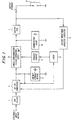
- Input EMI filter 1 accepts input voltage from system level power supply.
- Filter 1 can be configured in, for example, either simple first order L-C, Pi, T, or common/differential mode topology (depending on program requirements) to protect sensitive exciter electronics, and surrounding systems in close proximity to the exciter from conducted/radiated emissions/susceptibility.
- the EMI filter 1 commonly incorporates reverse polarity diode protection (not illustrated) to protect the exciter from inadvertent application of incorrect input polarity.
- Filtered input power supplied to the DC-DC converter 2 is transformed to high potential (on the order of, for example, 2-4 kV) for subsequent storage on energy storage device 3.
- high potential on the order of, for example, 2-4 kV
- an AC input power could also be used in conjunction with, for example, transformer rectification of the AC input power.
- a flyback type converter arrangement is used. Unlike forward converters, half/full bridges and the like, flyback converters allow exciter circuitry to operate over a wide input voltage range (on the order of 10-40 Vdc), while maintaining constant energy storage device 3 (tank capacitor) voltage.
- the energy storage device when the exciter circuit is first activated, or has just discharged, the energy storage device (load) approximates a short circuit. Conversely, prior to discharge, energy storage device 3 approximates an open circuit. Reflected impedance of this widely varying load is minimized through use of, for example, flyback type DC-DC converter which effectively isolates input supply from tank capacitor load.
- the DC-DC converter can be configured using both current and voltage control feedback loops to maximize power transfer efficiency while minimizing heating within both magnetic components and semiconductor switching devices.
- energy storage device 3 which can be, for example, a tank capacitor such as a reconstituted mica capacitor
- logic circuitry 4 monitors tank capacitor voltage.
- logic circuit 4 activates trigger circuit 5.
- the trigger circuitry may include an electromagnetic (transformer) coupling device or an optoelectronic coupling device. Regardless of the type of coupling used, trigger circuit 5 activates a single high voltage, di/dt thyristor switching device 6 allowing discharge of energy stored in energy storage device 3 to output PFN 7, and mating ignition lead (not illustrated) and igniter plug 8 (load) components. During discharge, the majority of energy stored in the energy storage device 3 is delivered to output PFN 7.
- commutating diode 10 Following delivery of energy from energy storage device 3 to output PFN 7, energy is subsequently recirculated from the load, through PFN 7 by commutating diode 10, creating a unipolar output waveform. This increases spark intensity (heat for given stored energy) since the waveform does not repeatedly cross zero, creating an oscillatory power waveform. Likewise, commutating diode 10 protects switching (PPT) thyristor 6 from stressful reverse bias transients which would occur without the commutating diode. Those skilled in the art will appreciate, however, that commutating diode 10 can be omitted if unipolar output is not desired.
- Exciter timing is accomplished by logic circuit 4.
- This circuit is constructed from a stable multivibrator which may be constructed in a variety of ways, as will later be described with respect to Figures 16 and 19.
- Logic circuit 4 provides a low duty cycle, low frequency output waveform with the period of the output waveform being inverse to the exciter spark rate. During the steady state operating case, logic circuit 4 generates pulses at any desired low steady state spark rate. Due to the low duty cycle, DC-DC converter 2 is activated only periodically. This causes the DC-DC converter to rapidly charge energy storage device 3, minimizing leakage current and power dissipation through single semiconductor switching device 6.
- logic circuit 4 is directed to increase charge pump frequency. By doing so, extreme ionization voltage requirements of severely worn igniter plug gaps, and dielectric insulating influence of quench media, e.g. water, fuel or high combustor pressure are quickly overcome.
- circuitry 11 can be configured with "time out” and manual override features to limit the amount of time that the exciter will attempt igniter "boost” operation and/or allow user override when a boost function is not desired. This prevents excess ignition system stress and allowing maximum operating flexibility.
- waveform analysis circuitry 11 can be omitted.
- the novel Pulse Power Thyristor (PPT) switching device by virtue of its unique design and construction, is capable of driving a variety of output pulse forming networks.
- the unique "double gate" PPT thyristor schematic symbol seen in block 6 of Figure 1 is used to differentiate the PPT device from conventional thyristor devices. Double gate leads denote the considerable interdigitation of gate and cathode structures and associated high (di/dt) current carrying capability of exemplary embodiments of the PPT according to the present invention.
- exemplary PPTs are specifically designed to reliably conduct pulse discharge waveforms.
- FIG. 2A illustrates differences between 60 Hz sinusoidal 12 and typical turbine engine ignition discharge waveforms 13.
- Exciter discharge waveforms ideally have zero rise time, and durations on the order of 30-200 ⁇ s. Rise time is important to ensure reliable igniter ionization and exciter peak power.
- a 60 Hz waveform has a low dv/dt and di/dt (long rise time), on the order of 4 ms, i.e., over two orders of magnitude longer.
- FIG. 2B illustrates operation of a conventional semiconductor switching device in a pulse discharge application.
- Waveform 270 represents the gate drive (capacitor voltage) of the conventional semiconductor switch. When the energy storage device, i.e., capacitor, is charged to, for example, 80V, this voltage is discharged through the conventional semiconductor switch. This begins in Figure 2B at time equal t 0 .
- Waveform 272 illustrates the anode-cathode current of the conventional semiconductor switching device as a function of time. Note the low di/dt and considerable lag time before reaching peak current.
- Waveform 280 is the PPT trigger capacitor voltage as a function of time, with triggering again occurring at t 0 .
- Waveform 282 shows the anode-cathode current for the exemplary PPT. Note the virtually infinite initial di/dt after triggering.
- Figure 2D is provided as a more robust comparison using a different time scale for clarity of the conventionally generated waveform 290 and a waveform 292 generated when an exemplary PPT is triggered. Note the very different di/dts, i.e., about 580 A/ ⁇ S for waveform 292 versus 118 A/ ⁇ S for waveform 290.
- FIGS. 3A and 3B illustrate differences in structure between traditional phase control thyristor structures and the novel PPT device.
- conventional phase control devices generically illustrated in Fig. 3A, have thin intrinsic Si structures for limiting blocking voltage to ⁇ 1.5 kV and also have essentially point contact gate regions 14 surrounded by the cathode region 15.
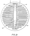
- the PPT (exemplified in Fig. 3B) utilizes interdigitated gate/cathode geometries 16 and 17. Note the relatively long gate/cathode periphery in Figure 3B as compared with that of Figure 3A. Interdigitation of the gate 16 and cathode 17 structures provides several important advantages relative to pulse discharge (di/dt) conduction.
- this extremely compact device e.g., having a package area of 1.5 in. by 1.75 in. or less, is well suited for the high rise time, di/dt waveforms associated with turbine engine ignition exciters.
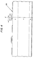
- the PPT emitter and gate geometries are such that the emitter center line is everywhere equidistant from the gate region, and less than a single diffusion length L from the gating region 400.
- FIG. 4 also shows exemplary widths of the various layers for purposes of illustration.
- the emitter region width Y is maintained at, for example, less than or equal to 10 times the gate (P base) region which, in this example, means that the emitter width Y is less than or equal to 0.06 inches. This ensures maximum use of the entire emitter area during initial triggering.
- the entire emitter region is activated preventing concentration of charge in proximity of the gate connection which occurs in conventional point contact thyristor designs, i.e., gate 14 in Figure 3A.
- This feature allows the entire device to modulate and conduct full anode current coincidental with the application of a (gate) trigger pulse.
- FIG. 5A illustrates several exemplary PFN's which can be used in exciter circuits according to the present invention. Since the PPT single semiconductor switching device has practically unlimited di/dt capability, the need for a saturable output network 22, which was required in conventional exciter circuits having semiconductor switches, is eliminated. For example, an air core output 18, inductive output 19, L-C peaking output 20 and bona fide high voltage, e.g., capacitor-transformer networks 21, can be used in exciter circuits according to the present invention without di/dt or dv/dt failure. Moreover, exciters utilizing simple L-C peaking networks 20 operate with higher reliability since di/dt effects of the resonant peaking capacitors 210 do not adversely affect the PPT. Consequently, simple air core and peaking outputs 18 and 20 can be utilized with low voltage (e.g., 3-10 kV) applications, increasing exciter peak power (reducing spark duration), thus improving ignition system performance.
- low voltage e.g., 3-10
- FIG. 5B illustrates one exemplary embodiment of a pulse forming network utilizing a transformer T1 and capacitor C2 combination.
- element C1 is the energy storage device 3 illustrated in Figure 1, and trigger circuit 5 and PPT 6 operate as described above.
- the operation of this circuit is as follows. Initially, the capacitor C1 (energy storage device 3) is charged by the DC-DC converter 2 (not shown in Figure 5B) via diode D1.
- the PPT6 is activated by trigger circuit 5
- a portion of the energy stored in capacitor C1 is delivered to transformer T1. Since the secondary load, e.g., a high tension igniter plug attached to V 0, initially acts as an open circuit, no energy is discharged through that path.
- Pulse capacitor C2 creates a pulse current through the flyback transformer action of transformer T1 which results in a high tension output voltage waveform. This output waveform is sufficient to ionize the igniter plug gap, allowing the remainder of the energy stored in capacitor C1 to dissipated in the spark plasma formed between the contacts of the high tension igniter plug.
- FIG. 5C illustrates an alternative exemplary topology for output PFN 7 utilizing a pulse capacitor C2 and transformer T1 combination.
- the system simultaneously charges the pulse capacitor C2 and the capacitor C1.
- Pulse capacitor C2 is charged through the primary winding of transformer T1 and safety resistor R1.
- the DC-DC converter 2 provides additional energy sufficient to charge both capacitors C1 and C2 at this time.
- energy does not bleed from the capacitor C1 into the pulse network as in the exemplary embodiment of Figure 5B.
- the energy stored in pulse capacitor C2 is shunted through the PPT 6 and the primary winding of transformer T1 resulting in a high tension output.
- transformer T1 significantly delay the current rise (di/dt) experienced by the PPT 6. This is due to the very low primary inductance relative to the amount of energy stored in the energy storage device 3.
- the primary winding of transformer T1 can be less than 25 microhenrys and preferably less than 20 microhenrys, e.g., 15.6 microhenrys.
- the core volume of transformer T1 can be less than 1.5 cubic inches and preferably less than 1 cubic inch, e.g., 0.92 cubic inches. This combination of transformer characteristics is possible due to the very high di/dt which the PPT is capable of handling and results in a relatively small exciter package with excellent performance.
- the topology described in Figure 5C provides several benefits when compared with that of Figure 5B.
- the topology of Figure 5C reduces voltage ring back stress (i.e., amplitude oscillations of the stored voltage) on the pulse capacitor C2.
- This beneficial effect can be seen by comparing the waveform of Figure 5D (voltage across the pulse capacitor C2 for the configuration of Figure 5B) with the waveform of Figure 5E (voltage across the pulse capacitor for the configuration of Figure 5C) and noting the lower amplitude oscillation for Figure 5E vs. Figure 5D (3.71kV vs. 4.92kV).
- discharge efficiency is improved since the energy stored in tank capacitor C1 is not expended on the pulse network. This also provides a greater exciter output voltage since all of the energy in the tank capacitor C1 can be used at the igniter plug.
- FIG. 6 illustrates a PPT structure according to an exemplary embodiment of the present invention.
- a unique pnp structure 240 is created by etching off the outer n+ region. Note that accordingly the N+ (cathode) region is not embedded in p-doped material. Since the (equivalent) npn transistor has been eliminated from the outermost regions, edge leakage current involves only the pnp structure. Additional etching, to the n-region, further reduces edge leakage to np diode levels by avoiding both npn and pnp gains. Since leakage current in the vicinity of the bevel edge area 23 is higher than in other areas, design according to this exemplary embodiment ensures that this surface leakage current will not be amplified by npn/pnp thyristor action.
- the bevel edge area 23 has been beveled in a manner that results in "spreading out” of the electric (field) potential lines 24 in the edge region 25.
- This unique positive beveling ensures bulk field breakdown since the surface electric field is spread out over a longer distance 26 than the bulk electric field, thereby promoting maximum theoretical (bulk) breakdown.
- all edge regions 27 outside of lines AA can be treated with electron radiation, further reducing pnp gain and associated leakage current.
- the emitter n+p junction and pn- regions 300 can also be made light sensitive by etching close to the pn- depletion regions. Triggering photons generate hole-electron pairs within these depletion regions resulting in injection from both p+ and n+ emitting regions 28 and 29.
- the device can thus be made sensitive to light radiation 30 by a unique etch which is pervasive over the entire gate-emitter length and provides exposure of n+p junction 300. This allows optional optoelectronic triggering as an alternative to electromagnetic triggering.
- the gate-emitter area is relatively great as compared to standard phase control thyristors because the device is extensively interdigitated. Due to considerably higher isolation achieved with optoelectronic coupling, exciter circuitry and "up stream" supply electronics are further protected from thyristor failure modes and effects.
- FIGS. 7A and 7B PPT edge beveling techniques according to the present invention are illustrated.
- the rounded region 31 of FIG. 7B can be desirable since cracks and fractures 32 of FIG. 7A caused during processing and handling are minimized by elimination of sharp edge 33. Cracks and chips contribute significantly to, and can cause failure of, semiconductors since high leakage current and low breakdown voltage result therefrom.
- FIG. 7A illustrates a sand blast method of die edge beveling wherein sand 34 is blasted from the bottom of chip (die) toward the top.
- FIG. 7B illustrates a second method of forming the bevel where the sharp edges 33 are replaced by rounded edges 31.
- the sand blast profile 34 shown in FIG. 7B eliminates the sharp edge since the distribution of the profile is such that some of the sand contacts the edge to round it off.
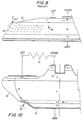
- FIG. 8 illustrates the conventional bevels for large, e.g., ⁇ 3 kV hockey puc type thyristors.
- Current thyristor structures use a double bevel angle, one negative 35, and one positive 36.
- Negative (Vbo) bevel 35 tends to concentrate E field lines when the device is forward biased (anode positive WRT cathode; forward blocking condition). This promotes dielectric breakdown at device surface rather than through (bulk) Si.
- phase control devices which typically must block voltage reliably bi-directionally (60 Hz sinusoid)
- a single PPT positive bevel 23 allows the device to realize (bulk) Si breakdown equal to theoretical Si breakdown.
- traditional hockey puc devices such as that illustrated in FIG. 8 can only achieve, for example, 80% of theoretical (bulk Si) breakdown voltage; and must utilize considerably more Si and wafer "real estate".
- the device blocks voltage like a diode. That is, by effectively shorting the p+n 37 and n+p 38 injecting junctions of the thyristor, npn and pnp gains are eliminated thereby reducing leakage current levels to those associated with diode structures and permitting high temperature (T j ⁇ 175°C) operation.
- FIG. 9B provides an isometric rendering of this emitter shorting technique.
- Anode shorting is accomplished by an etch down of the p region, e.g., at region 90, allowing penetration of n+, as depicted with Re (shunt resistors) and penetration of upper n+ layer into the p region.
- One method of cathode shorting similar to the technique used for the anode side, involves building etched "holes" 92 in the lower p+ region which penetrate adjacent n+ material.
- FIG. 10 illustrates a method according to an exemplary embodiment of the present invention for shorting both anode and cathode regions of both symmetric and asymmetric structures to achieve high blocking temperature capability and/or intrinsic inverse parallel (back bias) diode.
- Anode shorting reduces leakage current associated with imperfect passivation of the bevel area. Leakage current contributes considerably to exciter power losses during capacitor charge cycle. Likewise, since leakage current increases with temperature, exciter top-end operational temperature performance is limited. At high temperatures, thyristor leakage causes die heating which, if unchecked, will continue until catastrophic thermal runaway occurs.
- Anode shorting is accomplished by removing (either by grit blast or etch method, for example) the outer region 39 of the (P+) anode.
- a shorting metal such as Au-As 40 can be alloyed into the n- region making an efficient inverse diode 41.
- Cathode shorting can be accomplished by introducing internal shorts 43 over the entire emitter area or by providing external resistors 44 connected between cathode and gate terminals.
- Figure 10 illustrates how the outer bevel area can be modified to eliminate pnp and npn gain due to leakage current along surface of bevel for both symmetric and asymmetric thyristor structures. It will be appreciated by those familiar with semiconductor processing, that an asymmetric thyristor device would contain an additional n+ layer 46, allowing good ohmic contact using Al or similar metalization.
- FIGS. 11-15 illustrate an exemplary manufacturing technique of the PPT according to the present invention.
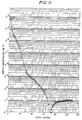
- Figure 11 illustrates the p region resulting from a diffusion of Al, Ga and B into both sides of a 37 mil thick Float Zoned Si wafer which was NTD (Nutron Transutated Doped) to approximately 10E13 (cm 3 ).
- the novel diffusion technique involves ion implanting and driving Al, Ga and B into the wafer with an approximately 16 hour 1275°C diffusion cycle.
- the Si is "capped” with layers of SiO 2 -Si 3 N 4 -SiO 2 thus preventing entrance of contaminants and outdiffusion.
- the capping/oxide layer materials and order of application were developed to provide a complete "cocoon" around the Si wafer, preventing entrance of contaminants or out diffusion.
- the oxide layers have been optimized to prevent cracking of the capping layer.
- the invention utilizes an ion implantation technique whereby Al, Ga and B are ion implanted through the oxide layer.
- AI is used to achieve a deep (approximately 4 mil) junction for high voltage capability, with a reasonable (approximately 16 hour 1275°C) diffusion. Due to the poor (approximately 4%) electrical affectivity of Al, Ga and B are introduced to increase concentration of active electrical acceptors for good ohmic contact and injection efficiency.
- conventional technology requires very long, high temperature diffusions, for example, about 135 hours at 1275°C, which are consequently prone to contamination from impurities, e.g. Na, which diffuses through (quartz) diffusion tubes increasing leakage current.
- Al is used since it is a fast diffusing (P type) dopant which will dope an Si lattice properly with 16 hr. 1250°C diffusion, as opposed to traditional B 135 hr. 1275°C diffusion.
- Al is a good fit in Si crystal, yielding low crystal stress.
- Al tends to bond with oxides creating oxide complexes lowering the effective doping to roughly 4%.
- Ga is used next to achieve higher doping concentration. Since Ga does not tend to form oxide complexes, it is a more efficient dopant. Again, diffusion time is short.
- B is used as a getter to "lift" impurities to the surface where they can be removed (etched off). Boron also provides improved ohmic contact. Ion implantation through oxide layer prevents out-diffusion and prevents contamination by, for example, Na, which would reduce carrier lifetime and increase leakage current.
- Exemplary embodiments of the present invention can utilize, for example, either diffusion or microwave oven dopant drive technology.
- the microwave technique can be implemented, for example, by replacing a standard fixed frequency magnetron with a variable frequency TWT (Traveling Wave Tube). This technique is favored since the TWT allows uniform RF heating of the Si, without heating the surrounding environment, thereby significantly reducing probability of contamination. This is a considerable advancement over current diffusion oven techniques since diffusion temperature can now approach Si melting temperature. Diffusion oven techniques are notably limited since quartz holding tubes used during the diffusion process are prone to sagging and devitrification at temperatures above 1200°C. The resulting pnp structure is then one side lapped to a p concentration on the order of 10E17.
- FIGS. 11-13 illustrate the complete profile which is capable of blocking, for example, >5 kV.
- FIG. 14 illustrates an exemplary method of forming the Si surface, i.e., defining the emitter, through the metalization process.
- the starting Si substrate is made by the sequential diffusion of Al, Ga and B into a, for example, 450 Ohm-cm, 37 mil NTD doped n- water thereby forming a pnp.
- One side of the wafer is lapped, etched and n+ phosphorus (POCL3) is predeposited and annealed to form a n+ pnp n+ wafer.
- POCL3 n+ phosphorus
- the anode side n+ is then removed by etching forming the n+ pnp structure.
- Figure 14 depicts a process that enables construction of a high voltage PPT type device that replaces planar diffusion fabrication methods, thus eliminating carrier lifetime reducing oxide mask/etch processes. That is, this process allows the thyristor to be etched, defined and metalized without any carrier lifetime reducing process steps, translating into lower on state (forward conduction) voltage.
- Figure 14 process depicts only one sided processing, exemplary embodiments of the present invention can be realized by applying the teachings of Figure 14 to both sides of the wafer.
- LPCVD low pressure chemical vapor deposited
- the etch process described in Step 7 can be accomplished by utilizing the selective etch process depicted in FIG. 15, and results in an emitter step height on the order of, for example, about 7.5 microns.
- the knee 150 on "square legend" curve of FIG. 15 illustrates the principle.
- the etch down rate abruptly changes (slows down) when N+ material has been removed, exposing underlying P material.
- This provides excellent uniformity and control which in turn allow the fine geometrics and uniform electrical performance of exemplary PPTs.
- an (SiO 2 ) oxide layer is not required to protect P material.
- the oxide layer used in fabrication of standard devices reduces carrier lifetime, increasing on state (forward conduction) voltage. Also shown in Figure 15 is the increase in sheet resistance as the NP junction is approached.
- Step 8 involves a non-selective Si etch that removes the remaining n material to allow reliable contact to the p gate region; followed by the removal of the nitride mask (9).
- Steps 10-21 involve the metalization process which is also used to alloy dope the gate regions for good ohmic contacts to the lightly doped gate regions. Al, Ti, and Ni are evaporated onto the emitter side and etch separated to obtain the gate-emitter lateral diode.
- Step 20 involves anode metalization using blanket Al-Ti-Ni. A result achieved using this process is to obtain good ohmic contacts to both lightly doped p Si (the gate region), the heavily doped P anode and the n+ cathode. God on-stage voltage is then achieved by alloying the AI into the Si with 500C sinter step 21.
- FIGS. 16A-16D illustrate a turbine engine ignition exciter circuit featuring the novel PPT switching device and automated feedback feature.
- the circuit has been divided into four (4) major functional blocks: EMI filter, diode converter charge pump, energy storage and switching and diagnostic section.
- DC input power is applied between VIT and VI_RTN terminals.
- Power is then fed through the EMI input filter consisting of L1, C1, C2, C3, L2 and L3.
- the EMI filter is configured to reduce common mode noise as well as differential mode signals which are generated outside the exciter.
- the filter also filters noise signals generated within the exciter system, preventing both conducted and radiated emission outside of the exciter housing.
- the exciter In the case of radiated emission, the exciter is generally constructed such that either a separate metallic sub-enclosure, or PC board with considerable ground plane area is utilized to trap signals, preventing radiation.
- the common/differential mode filter illustrated in Fig. 16A is just an example of one of a variety of viable circuit topologies which may be incorporated.
- Rectifier D1 serves as a reverse polarity protection diode which protects the exciter from inadvertent connection of the improper input voltage polarity between terminals VIT and VI_RTN.
- Z1 is a zener over voltage transient suppression diode.
- the zener diode is used to suppress voltage transients present on the input power cable, such as those induced during a lighting strike or aircraft/engine EEC switching.
- the zener may be replaced with a metal oxide varistor (MOV) or similar structure to accomplish this function, depending on specific program and design requirements.
- MOV metal oxide varistor
- F1 is a fuse designed to protect the DC source in the advent of a catastrophic failure, e.g. a short circuited switching FET (Q1) within the exciter. Other combinations of operational parameters can also cause fuse F1 to blow as described below with respect to Figures 17A-17C.
- Integrated circuits U1 and U5, in conjunction with corresponding filter capacitors C4, C5 and C14, C13 form linear voltage regulator networks which supply a highly regulated voltage, of appropriate potential to the CMOS and linear circuits within the exciter circuit.
- C6 is a high capacitance storage capacitor which forms part of the filter network and provides an energy reservoir to T1 thus reducing input current spikes and EMI noise.
- R1, C8, C9 and Z2 provide a stable reference voltage for the charge pump comparator U4A and tank voltage comparator U4B.
- U2 (Oscillator), R3, R4, (NPO capacitor) C10, R5, R6, Q3 and Q4 form an ultra stable oscillator which establishes the charge pump oscillating frequency and determines the spark rate of the exciter.
- the IC oscillator frequency is controlled by R4, R5 and C10. Values are selected to achieve maximum switching frequency to reduce component size.
- the IC contains "divide-by-n" circuitry which allows stable high frequency oscillator frequency to be divided, establishing exciter spark rate frequency. It will be appreciated that this method ensures extremely stable spark rate frequency over entire input voltage and environmental operating envelope.
- U3A Flip-Flop
- Q2, U4A Comparator
- R41 form the heart of the charge pump circuit.
- U2 provides a (spark rate frequency) clock signal to U3B which in turn activates U3A, turning on the charge pump at the (high frequency oscillator) clock rate set in U2.
- the Q ⁇ output of U3A turns Q2 "off", thus activating Q1, ensuring proper (saturating) gate drive.
- R41 and R7 are "pull-up" resistors for the "open collector” comparators outputs of U3A and U3B.
- R2 is an active pull-up for Q2 which provides drive to Q1.
- Z3 is a zener, which limits Q1 gate voltage to a safe value.
- Power transformer T1 is configured in a flyback configuration to minimize reflected load impedance and allow maximum output voltage over a widely varying input voltage range.
- Transformer T1 contains a tertiary, or feedback, winding to fully isolate the (voltage) feedback loop signal level electronics from high voltage present on secondary (tank capacitor) winding.
- Dual FET's can be used to prevent main switching FET Q1 from operating in linear region at low (exciter) input voltages.
- CMOS driver U3A
- Q2 can be used in a quasi-darlington configuration to ensure maximum Q1 gate drive (di/dt).
- Z3 zener diode is used to protect Q2 drain-source junction during T1 flyback; clamp Q1 gate drive to save level.
- Tank capacitor C15 is charged to the appropriate voltage (e.g., between 2-5 kV), through indirect action of the tertiary (feedback) winding on T1.
- the network comprised of diode D4, R14, R15, R16 and C16, C17 produces a stable (filtered) waveform which mirrors voltage present on C15.
- the comparator output toggles, resetting U3B (Flip Flop), turning off the charge pump (through U3A). Simultaneously, U3B (Flip Flop) activates Q5. Energy stored in C17 is then discharged through trigger transformer T2, Q5 to ground.
- Trigger transformer T2 generates a high voltage/current pulse which triggers the PPT (Pulse Power Thyristor) allowing energy stored in tank capacitor C15 to flow through PFN to the igniter plug load.
- Diode D5 serves as a recirculation diode for T7, protecting Q5 from induced (back) EMF.
- a simple air core inductive output L4 is depicted.
- any of the output PFN (Pulse Forming networks) defined in Fig. 5 may be used reliably, over the entire exciter operating envelope without limitation due to the unique high voltage, di/dt capability of the PPT.
- Other PFNs can also be used; for example, the impulse generator described below with respect to FIG. 20.
- Energy delivered to output inductor L4 is then delivered to the mating ignition lead and igniter plug load (not illustrated).
- the simple air core inductor L4 in this case, is used to adjust spark plasma discharge duration and peak power. This feature allows the exciter output to be precisely matched (tuned) to specific engine requirements and achieve maximum ignition performance. This is a significant advancement over conventional solid state exciter technology which must intentionally maximize exciter output duration, to minimize di/dt stress experienced by phase control type thyristor switching devices.
- the unipolarity, or commutating diode provides a return path for discharge current. This diode causes current to recirculate through the load, D6 and L4 until energy is completely expended.
- Back bias diode D3 provides a shunt path across the PPT for reverse currents generated immediately following PPT conduction, thus protecting the PPT when it enters the reverse recovery mode. Leads to diode D3 are illustrated in hidden lines since back bias diode D3 can be made integral to the PPT as shown in FIG. 10.
- Resistors R17 and R18 form a voltage divider which samples a portion of the output voltage and supplies it to the diagnostic circuit 166 for processing.
- Capacitors C18 and C19 block the high voltage dc present in the tank circuit, isolating sensitive "front end” processing circuitry form high voltage dc, allowing only the AC dynamic content to pass.
- Resistor R13 is a safety resistor which discharges C15 following removal of input power.
- Diagnostic signal processing is accomplished as follows. Signal input derived from the R17, R18 C18, C19 AC voltage divider circuit is applied to the diagnostic inputs of (comparators) U13A and U13B. Both comparators are set to measure the minimum output voltage of the exciter.
- U9 the diagnostic master clock (oscillator), provides one-shot timers U10 and U11 basic timing information for pulse duration and spark rate, respectively.
- One-shot U10 measures the time the exciter's output voltage waveform is above the comparator U1 minimum set point, established by resistors R34 and R35. When the exciter fires, the output voltage amplitude will quickly diminish to the igniter spark plasma sustaining voltage (e.g., ⁇ 50 V) within several microseconds if the igniter plug is not quenched.
- the igniter spark plasma sustaining voltage e.g., ⁇ 50 V
- U10 which is configured as a time out timer, generates a logic 1 output in response to the detection of a quenched igniter or an open circuit (lead).
- This logic 1 (from U10) is sent to U8A and U8B.
- U8A is configured as a retriggerable "one shot" providing a fixed output pulse to U12, a digitally controlled potentiometer. Each time U12 receives a pulse for U8A, the potentiometer value is incremented (one step).
- U10 simultaneously supplies the (same) logic 1 signal to U8B.
- U8B is also configured as a retriggerable "one-shot”. Based on component values of R26 and C29, U8B output pulse duration can be "programmed”.
- the exciter charge pump (DC-DC converter) enters a "burst mode", which causes the exciter to transition from a low steady state, maintenance spark rate mode to a high spark rate burst mode.
- the combined effects of increased spark rate, ionization voltage and delivered energy are intended to overcome plug wear and fouling. If the igniter plug fails to fire following each exciter discharge, tank voltage and stored energy are incrementally increased to the limit of U12.
- exciter charge pump will remain in high spark rate mode, as controlled by U8B, until the plug fires.
- U8B When the plug fires, U8B is reset, returning exciter to maintenance (steady state) low spark rate mode.
- U7 is a counter which keeps track of the digital potentiometer U12 "position". If the igniter does not fire after the digital potentiometer, U12 has increased exciter output to maximum voltage/energy, U7 generates a logic 1 output which is supplied to U6B input.
- U6B is configured as a latch. When logic 1 is received from U6B, output latches causing FET Q3 to close, tying the "Fail Igniter" line to ground. The Fail Igniter line is subsequently read by an engine EEC or similar device to determine whether a quenched igniter or open circuit ignition system fault exists.
- Exciter output voltage and spark rate analysis is accomplished by action of comparator U13B and subsequent circuitry.
- Output of U13B toggles each time exciter discharge occurs and exciter output voltage signal provided by output AC divider circuit (R17, R18, C18 and C19) exceeds the U13B setpoint value.
- This setpoint value is determined by resistor divider network comprised of R37 and R38.
- the network comprised of U13B, U11, U6A and associated support circuitry determines exciter output voltage and spark rate are within threshold limits.
- U11 which is configured as a "time-out" timer, fails to receive a reset pulse from U13B before the (spark rate) time out is reached, a logic 1 output is generated, indicating low exciter spark rate.
- the logic 1 signal is subsequently sent to U6A, which is configured as a latch.
- U6A then causes Q7 to tie the "Exciter Fail" line to ground providing an EEC or similar system analysis circuitry with an indication that annunciation exciter (low spark rate) fault has occurred.
- Circuitry comprised of FET Q8, R24, R25 and C28 provides a reset signal to U6 (A and B) when power is applied to the diagnostic circuit, resetting the diagnostic function.
- the circuit comprised of FET Q9 R29, R30, R31, R32 and C35 generates a "write" timing signal to U12 digital potentiometer. This "write” signal causes U12 to write the potentiometer setting to internal EEPROM circuitry, allowing the exciter to retain current output voltage and energy settings following removal of input power. By retaining settings, exciter output continually adjusts to changing engine and igniter plug wear conditions.
- charge and discharge cycles have been optimized to reduce stress on the PPT 6.
- the PPT 6 need block the stored voltage for less time, thereby placing less stress on the semiconductor switch.
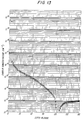
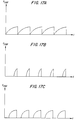
- FIG. 17A-C wherein the graph of FIG. 17A illustrates conventional charging techniques which typically charge an energy storage device over a relatively long period of time.
- systems according to the present invention charge the energy storage device in significantly shorter periods of time as illustrated in the graphs of FIGS. 17B and 17C.
- 17C may represent charging times for the same circuit operating at an ambient temperature of 121°C with the battery supplying 9 1/2 volts.
- the input current will increase along with the charging time for the storage capacitor due to I 2 /R losses. This has several implications.
- the fuse F1 illustrated in FIG. 16A which protects a circuit may blow if the input current increases beyond that at which the fuse is rated.
- the increased charging time may lead to a thermal runaway (breakdown) of the PPT 6.
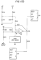
- a low voltage lockout feature which prevents the circuit from operating when the input voltage is lower than a predetermined threshold.
- the predetermined threshold can be selected to be any voltage level which is less than a desired operating input voltage depending upon various design considerations. For example, for a nominal input voltage rating of 28 volts, a threshold of 91 ⁇ 2 volts can be selected whereupon the circuitry will not operate if the input voltage drops below 91 ⁇ 2 volts.
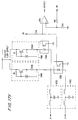
- the input voltage is monitored by comparator 234 through a voltage divider comprised of resistors R270 and R280 and filtered by capacitor C320.
- a stable voltage reference is established by bias resistors R250 and R260, zener diode Z55 and filtered by capacitor C300. This voltage reference is then input to the inverting terminal of comparator 234.
- Resistors R240 and R230 provide a comparator hysteresis (e.g., approximately 0.3 V) which prevents oscillatory operation when the input voltage has a value which is approximately similar to that of the reference voltage applied at the inverting terminal of comparator 234.
- the exciter is constantly provided with an input voltage, i.e., the exciter is hard-wired to the aircraft DC power bus with no switches between the exciter and the bus.
- activation and deactivation of the circuitry is achieved through relatively small gauge wiring linking the FADEC to, for example, the low voltage lockout circuitry illustrated in Figure 17B.
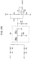
- Two exemplary embodiments of FADEC input control block 300 will now be described with respect to Figures 17C and D, respectively.
- FIG. 17C two FADEC channels A and B are illustrated at the left hand side of the figure.
- Several high voltage diodes 1701 are included to provide a diode "OR" function which allows activation of the exciter by turning on either the A or B FADEC control channel.
- a typical T filter arrangement including two inductors, a feed-through capacitor and a transorb (MOV).
- MOV transorb
- FADEC activation causes current to flow from the 8-volt supply bus through the 7.87 k ⁇ resistor. This drives the inverting input of comparator U8A below the threshold voltage established by the 10 k ⁇ and 20 k ⁇ resistive divider network attached to the non-inverting comparator input.
- the 1 M ⁇ resistor provides hysteresis in case the reference voltage and applied control voltage should be similar.
- comparator U8A When either channel A or B are active, the output of comparator U8A floats the non-inverting input of comparator 234 in Figure 17B low, thereby allowing input voltage information to be processed by comparator 234. Lack of FADEC input, on the other hand, causes the output of comparator U8A in Figure 17C to tie the non-inverting input of comparator 234 in Figure 17B low, thereby inhibiting the processing of input voltage information and turning the exciter off.
- the exemplary embodiment illustrated in Figure 17C describes various component values which, of course, are simply illustrative in nature and may be varied to accommodate, for example, different voltages and other design parameters.
- FIG 17D provides an alternative exemplary embodiment for FADEC input control block 300.
- opto-isolators are utilized to provide complete electrical isolation between the signal processing circuitry, the FADEC, and each FADEC channel.
- protection against transients is provided by the EMI filters 1705.
- Each channel A and B also has an opto-isolator 1708.
- a single EMI filter 1705 and a single opto-isolator 1708 could be employed to service both channels A and B if a diode "OR" circuit was provided upstream of these elements as, for example, illustrated in Figure 17C.
- a constant current source 1709 is provided to establish constant current to each opto-isolator 1708.
- the opto-isolator transistors are used to tie the inverting input of comparator U8A low when the exciter is to be activated by the FADEC.
- the biasing of comparator U8A is relative to the exciter's internal 8-volt regulated bus.
- the opto-isolators 1708 are referenced to the 28-volt DC airframe bus to prevent excess loading of the regulated 8-volt exciter bus at high temperatures.
- FADEC input control can be provided without low voltage lockout circuitry.
- the FADEC input control could instead be connected directly to node 302 to selectively short R220 without the low voltage lockout circuitry being present.
- FADEC input control provides several advantages over conventional techniques which use a switching approach to providing the raw input voltage. For example, the large gauge wiring required in these conventional solutions and switching to the airframe bus are no longer necessary.
- FIG. 18 illustrates an optical PPT triggering variation of the energy storage circuit described in FIG. 16B.
- Optical triggering can be used, for example, in applications where protection against the effects of electromagnetic pulses or pulse transformer failure is desired.
- PPT trigger transformer T2 is replaced with an LED optoelectronic triggering device.
- the device in FIG. 17 (illustrated by hidden lines) is a hybrid circuit containing the PPT die, an LED optoelectronic triggering means and integral back bias diode (as described previously in FIG. 10). In this case, energy stored in C17 is delivered to LED when Q5 is activated by exciter spark rate control flip-flop U3B.
- An integral back bias diode eliminates the need for separate discrete back bias diode D3 illustrated in FIG. 16B. It will be appreciated that a variety of physical configurations and triggering devices can be utilized in the optoelectronic triggering case. Alternate fabrication methods can include alternate trigger source technologies, e.g. LASER. Likewise, the fabrication method can include either integral (on hybrid) LED/LASER triggering, or external triggering. In the latter case, an LED or LASER diode is housed in a separate package, and optically connected to suitable PPT (optical) package via fiberoptic cable.
- PPT optical
- a microprocessor/controller circuit embodiment is described.
- DC power applied to the exciter input FILTER F1 is filtered to prevent entrance or escape of radiated and conducted noise emissions as with prior embodiments.
- Filtered power is applied to a stable voltage REGULATOR which provides regulated power to all subsequent (signal level) circuitry.
- the filter also supplies power to energy storage device C3 and (flyback) power transformer T1.
- a microprocessor/controller controls all exciter energy management, feedback and diagnostic reporting functions.
- Exciter parameters e.g., spark rate, output voltage, stored energy, diagnostic limits and feedback control loop setpoints can be readily changed through modification of software code contained within on board ROM (not shown), without modification of exciter physical circuitry.
- a variety of memory technologies including ROM, EPROM EEPROM and WORM may be utilized depending on program objectives.
- the microcontroller can include, for example, 8-bit or higher architecture. Peripheral devices and support circuitry will vary depending on the specific microcontroller being used.
- the exemplary circuitry illustrated in FIG. 19 is based on a 16-bit architecture, containing a 16-bit data bus, ALU and registers. A 20MHz or higher microprocessor clock frequency can be used to ensure the microcontroller accurately resolves fast rise time transient events.
- the microprocessor can execute commands in approximately 200 ns. This time window allows extremely high resolution (and direct analysis) of pulse discharge events such as those generated during exciter discharge.
- the micro-controller can contain, for example, four 16-bit timers/counters with four synchronous outputs, eight vector interrupt sources and uses CMOS technology for low power consumption.
- Data such as charge pump transformer primary current, tank capacitor voltage and discharge voltage waveform are all connected to a central multiplexer (MUX).
- the MUX which is controlled directly by the microprocessor, supplies appropriate analog channel to the high speed analog-to-digital converter A/D for subsequent digitization.
- the micro-controller When power is applied to the circuit, the micro-controller begins acquiring date from the multiplexed data line. Voltage across the charge pump (current sense) resistor R1 is then routed to the high speed A/D, converted to a digital value and read by the micro-controller.
- DRIVER DR1 is triggered which in turn activates main switching FET Q1. This initiates current flow through primary of power transformer T1. As current increases linearly through the primary winding, voltage drop across sense resistor R1 increases.
- the micro-controller is continually receiving multiplexed data from the MUX.
- V R1 reaches predetermined (software) setpoint value (during subsequent V R1 read cycles) the micro-controller then removes drive (logic 1) level from DRIVER DR1 line.
- This causes transformer T1 to "flyback", releasing energy stored in the transformer core through D1 into the tank capacitor C1, and D4, R2 into energy “mirror”/trigger capacitor C2.
- tank capacitor C1 Since D1 and D4 conduct together, the voltage on tank capacitor C1 is proportional to the voltage on "mirror"/trigger capacitor C2 in accordance with the transformer T1 turns ratio ⁇ .
- the high voltage/current output stage is electrically isolated from low voltage signal level logic and control circuitry.
- commutating diode D3 causes discharge current to recirculate, giving the output waveform characteristic unipolar shape.
- Back bias diode D2 provides a shunt path across PPT immediately following triggering, thus protecting the PPT from transient (reverse polarity) currents generated during the PPT reverse recovery (turning off) period.
- Resistors R5 and R6 form a voltage divider which provides a relatively small amplitude signal which mirrors exciter discharge output waveform. Signal is fed through a single dc blocking capacitor C4 to the MUX, A/D and finally to the micro-controller.
- a timer within the microprocessor is started.
- the duration of diagnostic signal provided by R5, R6 and C4 is short (on the order of, for example, 20-200 ⁇ s) depending on specific exciter design.
- the diagnostic signal time window is considerably longer (several orders of magnitude) due to the RC time constant of C1, R5 and R6.
- igniter/lead quench/open circuit is inferred once diagnostic signal duration exceeds microprocessor predetermined (time out) interval.
- the microprocessor may increase the spark rate, output voltage/energy, report failure to EEC or similar communication device, or any combination of the above.
- the microprocessor executes a preprogrammed "time out" cycle before repeating charge pump, discharge and diagnostic evaluation cycle, thus achieving constant exciter spark rate.
- This microprocessor based system is completely flexible, minimizing hardware and wiring changes necessary for various applications and mission profile changes since all exciter activities are software controlled.
- FIG. 20 illustrates an exemplary delta function, or impulse, generator. Unlike traditional ignition exciter transformer-capacitor PFN topologies, this circuit eliminates the trigger capacitor, enabling a impulse (delta function) output. Since the trigger capacitor charge time is eliminated, a true impulse, or step function output is achieved. It will be appreciated by those familiar with both conventional semiconductor (low voltage) and conventional air gap (high voltage) ignition systems, high dv/dt significantly improves ability of igniter plug to fire during quench conditions.
- the impulse voltage requirements increase. That is, the number of volt-seconds required for ionization increase.
- a low tension semiconductor type igniter plug may require 3 kV for 3 ⁇ s to ionize under ambient conditions. At full combustor pressure, or when contaminated, the igniter may require 3 kV for 100 ⁇ s.
- the igniter may be ionized by application of a 6 kV 50 ⁇ s pulse.
- a charge pump (not illustrated), provides energy through rectifier diode D1 to tank capacitor C TANK , via I CHARGE .
- PPT switching device is triggered (by either electromagnetic or optoelectronic means) when tank capacitor has reached full charge (energy).
- the PPT is illustrated here with an integral back bias diode although this diode need not be integral as discussed earlier.
- a unit step function of amplitude V the tank capacitor voltage is imparted on air core output inductor (comprised of L1 and L2).
- an amplified voltage determined by the turns ratio N1/N2 is applied to the igniter plug, thereby forcing reliable ionization.
- Exciter discharge waveform characteristics may be controlled by the output inductor turns ratio, and recovery time of diodes D2 and D3 and circuit damping can be controlled by impedances Z 1 and Z 2 .
- FIGS. 21-23 illustrate another exemplary embodiment of a PPT structure according to the present invention.
- FIG. 21 illustrates cuts or breaks 200, e.g., 1-3 mils, in the cathode metalization. These cuts or breaks 200 force cathode current into the underlying P-doped material. The resulting small, e.g., 0.002 ohm, ballast resistor created in each cathode "finger” tends to equalize cathode current preventing current "hogging" by a single finger or group of fingers.
- FIG. 22 is a cross-sectional view taken along line A-A in FIG. 21, but in an equivalent circuit schematic interpretation. Note the cathode (emitter) ballast resistors 212 which cause the equivalent circuit to change from a single larger SCR (not shown) to several smaller finger SCRs 220 in parallel which each divide and share current equally. To ensure that finger SCRs 220 trigger first, the central cathode region 224 can be internally shorted 226 to reduce its gating sensitivity. The central region would then be turned on by the relatively slow plasma spreading from the finger areas. These shorts 226 would also be effective in improving temperature and di/dt performance.
- FIG. 23 is a cross-sectional view taken across lines B-B of FIG. 21 illustrating the breaks 200 in a particular finger.
- Engine exciter circuitry according to the foregoing exemplary embodiments and other embodiments not discussed herein provide many advantages over conventional exciter technology.
- the use of a novel semiconductor switching device, the PPT, having high di/dt characteristics (e.g., 200-1000 amperes/microsecond or higher as compared with conventional devices which provide about 100-150 amperes/microsecond) and high voltage blocking capabilities (e.g., greater than 2 kV) in a relatively small physical package (e.g., having an area about 1.5 inches x 1.75 inches or smaller) provides numerous advantages for overall circuit design, operation and cost, some of which have been described above.
- Another advantage is the longer lifetime of circuits according to the present invention. Whereas conventional exciter circuits have a lifetime expectancy of, for example, about one million shots, circuits according to the present invention are expected to have a lifetime of about, for example, sixty million shots.
- I RMS 70A
- I PK 700A
- di/dt 1000 A/ ⁇ s 0.3" diameter die
- I RMS 25A
- I PK 250A
- di/dt 500 A/ ⁇ s
Landscapes
- Engineering & Computer Science (AREA)
- Chemical & Material Sciences (AREA)
- Combustion & Propulsion (AREA)
- Mechanical Engineering (AREA)
- General Engineering & Computer Science (AREA)
- Ignition Installations For Internal Combustion Engines (AREA)
- Generation Of Surge Voltage And Current (AREA)
Applications Claiming Priority (2)
| Application Number | Priority Date | Filing Date | Title |
|---|---|---|---|
| US598904 | 1990-10-16 | ||
| US08/598,904 US5656966A (en) | 1994-03-09 | 1996-02-09 | Turbine engine ignition exciter circuit including low voltage lockout control |
Publications (3)
| Publication Number | Publication Date |
|---|---|
| EP0789144A2 true EP0789144A2 (de) | 1997-08-13 |
| EP0789144A3 EP0789144A3 (de) | 1998-08-26 |
| EP0789144B1 EP0789144B1 (de) | 2003-09-10 |
Family
ID=24397417
Family Applications (1)
| Application Number | Title | Priority Date | Filing Date |
|---|---|---|---|
| EP97300836A Expired - Lifetime EP0789144B1 (de) | 1996-02-09 | 1997-02-10 | Zündkreis für eine Turbine mit Niederspannungsaussperrungsschaltung |
Country Status (5)
| Country | Link |
|---|---|
| US (2) | US5656966A (de) |
| EP (1) | EP0789144B1 (de) |
| AT (1) | ATE249580T1 (de) |
| CA (1) | CA2197048C (de) |
| DE (1) | DE69724678T2 (de) |
Cited By (4)
| Publication number | Priority date | Publication date | Assignee | Title |
|---|---|---|---|---|
| US6838779B1 (en) | 2002-06-24 | 2005-01-04 | Hamilton Sundstrand Corporation | Aircraft starter generator for variable frequency (vf) electrical system |
| US6838778B1 (en) | 2002-05-24 | 2005-01-04 | Hamilton Sundstrand Corporation | Integrated starter generator drive having selective torque converter and constant speed transmission for aircraft having a constant frequency electrical system |
| EP1834083A4 (de) * | 2004-12-23 | 2010-09-29 | Pratt & Whitney Canada Corp Pr | Zündung mit variabler frequenz |
| EP2551888A3 (de) * | 2011-07-28 | 2014-01-29 | Rolls-Royce plc | Elektrische Entladungsvorrichtung |
Families Citing this family (40)
| Publication number | Priority date | Publication date | Assignee | Title |
|---|---|---|---|---|
| US6195247B1 (en) * | 1998-06-02 | 2001-02-27 | Pratt & Whitney Canada | Exciter controlled by FADEC system |
| EP1155485B1 (de) * | 1998-12-23 | 2007-05-09 | Champion Aerospace Inc. | Induktiver zündkreis |
| US6249123B1 (en) * | 1999-04-20 | 2001-06-19 | Honda Of America, Mfg., Inc. | Automated determination of the size of a gap in an article of manufacture during assembly of the article of manufacture |
| US6104143A (en) * | 1999-10-01 | 2000-08-15 | Peabody Engneering Corporation | Exciter circuit with solid switch device separated from discharge path |
| US6603216B2 (en) | 2001-10-10 | 2003-08-05 | Champion Aerospace Inc. | Exciter circuit with ferro-resonant transformer network for an ignition system of a turbine engine |
| US8259753B2 (en) * | 2002-02-26 | 2012-09-04 | General Electric Company | Systems and methods for short range RF communication |
| US7236503B2 (en) * | 2002-02-26 | 2007-06-26 | General Electric Company | Short range RF communication for jet engine control |
| US7137385B2 (en) * | 2002-11-01 | 2006-11-21 | Visteon Global Technologies, Inc. | Device to provide a regulated power supply for in-cylinder ionization detection by using the ignition coli fly back energy and two-stage regulation |
| US7005855B2 (en) | 2003-12-17 | 2006-02-28 | Visteon Global Technologies, Inc. | Device to provide a regulated power supply for in-cylinder ionization detection by using the ignition coil fly back energy and two-stage regulation |
| US7355300B2 (en) * | 2004-06-15 | 2008-04-08 | Woodward Governor Company | Solid state turbine engine ignition exciter having elevated temperature operational capability |
| US7116003B2 (en) * | 2004-07-14 | 2006-10-03 | Hamilton Sundstrand Corporation | Aircraft starter/generator electrical system with mixed power architecture |
| US7509812B2 (en) * | 2004-08-20 | 2009-03-31 | Hamilton Sundstrand Corporation | Dual ignition system for a gas turbine engine |
| US7095601B2 (en) * | 2004-08-20 | 2006-08-22 | Hamilton Sundstrand Corporation | High energy primary spark ignition system for a gas turbine engine |
| EP1633096A1 (de) * | 2004-08-26 | 2006-03-08 | St Microelectronics S.A. | Bestimmung der Träger- und Symbolfrequenz eines Signals |
| US8032095B1 (en) | 2005-03-03 | 2011-10-04 | Marvell International Ltd. | Method and apparatus for detecting carrier leakage in a wireless or similar system |
| US7768767B2 (en) * | 2006-05-05 | 2010-08-03 | Pratt & Whitney Canada Corp. | Triggered pulsed ignition system and method |
| US8381187B2 (en) * | 2006-09-21 | 2013-02-19 | International Business Machines Corporation | Graphical user interface for job output retrieval based on errors |
| EP2356327B1 (de) * | 2008-11-13 | 2014-12-31 | Sikorsky Aircraft Corporation | Adaptives system mit integrierter sicherheit für fadec-gesteuerte gasturbinentriebwerke |
| US8305049B2 (en) * | 2009-04-06 | 2012-11-06 | Hamilton Sundstrand Corporation | Starter voltage reducing synchronous machine |
| US8130008B2 (en) * | 2010-03-01 | 2012-03-06 | Infineon Technologies Ag | Integrated circuit with a radiation-sensitive thyristor structure |
| US20130111914A1 (en) * | 2011-04-27 | 2013-05-09 | Champion Aerospace Llc | Aircraft ignition system and method of operating the same |
| US9537307B2 (en) | 2011-07-19 | 2017-01-03 | Hamilton Sundstrand Corporation | Overvoltage protection method and device |
| US9013856B2 (en) * | 2011-08-29 | 2015-04-21 | Honeywell International Inc. | Ignition exciter system and ignition exciter circuit |
| JP6063677B2 (ja) * | 2012-09-06 | 2017-01-18 | ローム株式会社 | 信号検出回路及びイグナイタ |
| US9135755B2 (en) | 2013-08-02 | 2015-09-15 | Pratt & Whitney Canada Corp. | Health monitoring of igniters |
| US9399954B2 (en) * | 2014-03-17 | 2016-07-26 | Unison Industries, Llc | Ignition exciter discharge switch |
| US9579517B2 (en) | 2014-09-08 | 2017-02-28 | Medtronic, Inc. | Transformer-based charging circuits for implantable medical devices |
| US9724528B2 (en) | 2014-09-08 | 2017-08-08 | Medtronic, Inc. | Multiple transformer charging circuits for implantable medical devices |
| US9604071B2 (en) | 2014-09-08 | 2017-03-28 | Medtronic, Inc. | Implantable medical devices having multi-cell power sources |
| US9861827B2 (en) | 2014-09-08 | 2018-01-09 | Medtronic, Inc. | Implantable medical devices having multi-cell power sources |
| US9861828B2 (en) | 2014-09-08 | 2018-01-09 | Medtronic, Inc. | Monitoring multi-cell power source of an implantable medical device |
| US9539435B2 (en) | 2014-09-08 | 2017-01-10 | Medtronic, Inc. | Transthoracic protection circuit for implantable medical devices |
| US9643025B2 (en) | 2014-09-08 | 2017-05-09 | Medtronic, Inc. | Multi-primary transformer charging circuits for implantable medical devices |
| FR3032232B1 (fr) | 2015-01-30 | 2017-03-10 | Meggitt (France) | Generateur d'allumage a haute energie notamment pour turbine a gaz |
| US10801414B2 (en) * | 2017-01-24 | 2020-10-13 | Honeywell International Inc. | Gas turbine engine including a rectifierless electronic control unit and method for supplying power to same |
| US11356024B2 (en) | 2018-12-06 | 2022-06-07 | Unison Industries, Llc | Ignition exciter assembly and method for charging a tank capacitor for an ignition exciter |
| CN110233576A (zh) * | 2019-07-11 | 2019-09-13 | 贵州航天林泉电机有限公司苏州分公司 | 带有唤醒功能的车载电机驱动器辅助电源装置 |
| US11165422B2 (en) | 2020-04-01 | 2021-11-02 | Delta Electronics, Inc. | Gate driver circuit with reduced power semiconductor conduction loss |
| US12486822B2 (en) * | 2022-12-08 | 2025-12-02 | Hamilton Sundstrand Corporation | Engine ignition systems and control methods therefor |
| CN116316084B (zh) * | 2023-03-15 | 2026-04-28 | 电子科技大学 | 一种基于阴极短路栅控晶闸管的油气点火装置 |
Family Cites Families (23)
| Publication number | Priority date | Publication date | Assignee | Title |
|---|---|---|---|---|
| US3569727A (en) * | 1968-09-30 | 1971-03-09 | Bendix Corp | Control means for pulse generating apparatus |
| US3651341A (en) * | 1970-05-28 | 1972-03-21 | Charles L Shano | Capacitor discharge pulse source |
| US3978513A (en) * | 1971-05-21 | 1976-08-31 | Hitachi, Ltd. | Semiconductor controlled rectifying device |
| US3739235A (en) * | 1972-01-31 | 1973-06-12 | Rca Corp | Transcalent semiconductor device |
| US4177479A (en) * | 1975-09-09 | 1979-12-04 | Bbc Brown Boveri & Company | Electrical circuit with a high-frequency thyristor fired by blocking leakage current |
| CA1163020A (en) * | 1980-05-23 | 1984-02-28 | Victor A.K.. Temple | High voltage semiconductor device having improvements to the dv/dt capability and plasma spreading |
| JPS5739574A (en) * | 1980-08-22 | 1982-03-04 | Toshiba Corp | Semiconductor device |
| US4536783A (en) * | 1983-11-14 | 1985-08-20 | Westinghouse Electric Corp. | High di/dt, light-triggered thyristor with etched moat current limiting resistors |
| DE3731412A1 (de) * | 1986-11-08 | 1988-05-11 | Bosch Gmbh Robert | Hochspannungsschalter |
| US4833369A (en) * | 1987-10-14 | 1989-05-23 | Sundstrand Corp. | Constant spark rate ignition exciter |
| FR2636678B1 (fr) * | 1988-09-20 | 1994-04-15 | Labo Industrie | Generateur d'allumage haute energie notamment pour turbine a gaz |
| US5148084A (en) * | 1988-11-15 | 1992-09-15 | Unison Industries, Inc. | Apparatus and method for providing ignition to a turbine engine |
| US5065073A (en) * | 1988-11-15 | 1991-11-12 | Frus John R | Apparatus and method for providing ignition to a turbine engine |
| US5245252A (en) * | 1988-11-15 | 1993-09-14 | Frus John R | Apparatus and method for providing ignition to a turbine engine |
| US5053913A (en) * | 1989-02-17 | 1991-10-01 | Unison Industries Limited Partnership | Capacitive discharge ignition exciter using scr discharge switches |
| DE3917968A1 (de) * | 1989-06-02 | 1990-12-06 | Bosch Gmbh Robert | Halbleiterschalter, insbesondere als hochspannungs-zuendschalter fuer brennkraftmaschinen |
| JP2651728B2 (ja) * | 1989-12-15 | 1997-09-10 | 横河航空電機株式会社 | 点火装置 |
| US5032969A (en) * | 1990-02-15 | 1991-07-16 | Cooper Industries, Inc. | Turbine engine igniter exciter circuit |
| EP0481609A3 (en) * | 1990-10-19 | 1992-09-02 | Lucas Industries Public Limited Company | Ht exciter for turbine ignition system |
| US5092424A (en) * | 1990-12-03 | 1992-03-03 | Bose Corporation | Electroacoustical transducing with at least three cascaded subchambers |
| US5416689A (en) * | 1992-12-17 | 1995-05-16 | Digital Equipment Corporation | Current mode switching power supply overload protection circuit with false fault condition screening |
| US5592118A (en) * | 1994-03-09 | 1997-01-07 | Cooper Industries, Inc. | Ignition exciter circuit with thyristors having high di/dt and high voltage blockage |
| FR2717534B1 (fr) * | 1994-03-17 | 1996-05-15 | Eyquem | Générateur d'allumage haute énergie notamment pour turbine à gaz. |
-
1996
- 1996-02-09 US US08/598,904 patent/US5656966A/en not_active Expired - Lifetime
-
1997
- 1997-02-07 CA CA002197048A patent/CA2197048C/en not_active Expired - Fee Related
- 1997-02-10 EP EP97300836A patent/EP0789144B1/de not_active Expired - Lifetime
- 1997-02-10 AT AT97300836T patent/ATE249580T1/de not_active IP Right Cessation
- 1997-02-10 DE DE69724678T patent/DE69724678T2/de not_active Expired - Lifetime
- 1997-04-01 US US08/831,518 patent/US5852381A/en not_active Expired - Lifetime
Cited By (5)
| Publication number | Priority date | Publication date | Assignee | Title |
|---|---|---|---|---|
| US6838778B1 (en) | 2002-05-24 | 2005-01-04 | Hamilton Sundstrand Corporation | Integrated starter generator drive having selective torque converter and constant speed transmission for aircraft having a constant frequency electrical system |
| US6838779B1 (en) | 2002-06-24 | 2005-01-04 | Hamilton Sundstrand Corporation | Aircraft starter generator for variable frequency (vf) electrical system |
| EP1834083A4 (de) * | 2004-12-23 | 2010-09-29 | Pratt & Whitney Canada Corp Pr | Zündung mit variabler frequenz |
| US8978355B2 (en) | 2004-12-23 | 2015-03-17 | Pratt & Whitney Canada Corp. | Variable rate ignition |
| EP2551888A3 (de) * | 2011-07-28 | 2014-01-29 | Rolls-Royce plc | Elektrische Entladungsvorrichtung |
Also Published As
| Publication number | Publication date |
|---|---|
| CA2197048A1 (en) | 1997-08-10 |
| CA2197048C (en) | 2005-01-25 |
| EP0789144B1 (de) | 2003-09-10 |
| DE69724678T2 (de) | 2004-07-29 |
| ATE249580T1 (de) | 2003-09-15 |
| EP0789144A3 (de) | 1998-08-26 |
| US5656966A (en) | 1997-08-12 |
| DE69724678D1 (de) | 2003-10-16 |
| US5852381A (en) | 1998-12-22 |
Similar Documents
| Publication | Publication Date | Title |
|---|---|---|
| EP0789144B1 (de) | Zündkreis für eine Turbine mit Niederspannungsaussperrungsschaltung | |
| US5592118A (en) | Ignition exciter circuit with thyristors having high di/dt and high voltage blockage | |
| WO1995024554A9 (en) | A turbine engine ignition exciter circuit | |
| US3169212A (en) | Transistorized ignition system | |
| US5179248A (en) | Zener diode for protection of semiconductor explosive bridge | |
| CA2128036C (en) | Ignition system using multiple gated switches with variable discharge energy levels and rates | |
| US7355300B2 (en) | Solid state turbine engine ignition exciter having elevated temperature operational capability | |
| US5044349A (en) | High-voltage switch | |
| JPH02241933A (ja) | ガスタービンエンジン点火装置 | |
| EP3196444B1 (de) | Festkörperfunkenvorrichtung | |
| KR900000829B1 (ko) | 광기전력 릴레이 | |
| RU2742343C1 (ru) | Короткозамкнутый полупроводниковый элемент и способ его эксплуатации | |
| EP0612376B1 (de) | Kapazitives zündsystem mit selbstauslösendem halbleiterschalter | |
| US5604653A (en) | Protection component for a three-phase alternator used in automobile vehicles | |
| EP0190162B1 (de) | Gesteuerter einschaltbarer thyristor | |
| US6403988B2 (en) | Semiconductor device with reverse conducting faculty | |
| EP0071526B1 (de) | Zündsystem für Brennkraft Maschine | |
| US4110638A (en) | Configuration for reducing the turn-off time of a thyristor | |
| EP0106658B1 (de) | Temperaturstabiler selbstschützender Thyristor und Herstellungsverfahren | |
| NL2020058B1 (en) | Semiconductor device | |
| JP3152040B2 (ja) | 内燃機関用点火装置 | |
| KR20180124908A (ko) | 점화실 내의 공기/연료 혼합물을 점화시키는 점화 장치 | |
| CN1162347A (zh) | 内燃机点火装置 | |
| EP0210299A2 (de) | Schutzanordnung für die Schalteinrichtung eines Impulsgebers mit kapazitiver Last | |
| Weise et al. | Performance spectrum of optical triggered thyristor switches for electric weapon system |
Legal Events
| Date | Code | Title | Description |
|---|---|---|---|
| PUAI | Public reference made under article 153(3) epc to a published international application that has entered the european phase |
Free format text: ORIGINAL CODE: 0009012 |
|
| AK | Designated contracting states |
Kind code of ref document: A2 Designated state(s): AT BE CH DE DK ES FI FR GB GR IE IT LI LU MC NL PT SE |
|
| AX | Request for extension of the european patent |
Free format text: LT PAYMENT 970228;SI PAYMENT 970228 |
|
| RAP1 | Party data changed (applicant data changed or rights of an application transferred) |
Owner name: COOPER INDUSTRIES, INC. |
|
| PUAL | Search report despatched |
Free format text: ORIGINAL CODE: 0009013 |
|
| AK | Designated contracting states |
Kind code of ref document: A3 Designated state(s): AT BE CH DE DK ES FI FR GB GR IE IT LI LU MC NL PT SE |
|
| AX | Request for extension of the european patent |
Free format text: LT PAYMENT 970228;SI PAYMENT 970228 |
|
| RAP1 | Party data changed (applicant data changed or rights of an application transferred) |
Owner name: COOPER AUTOMOTIVE PRODUCTS, INC. |
|
| 17P | Request for examination filed |
Effective date: 19981201 |
|
| 17Q | First examination report despatched |
Effective date: 20000211 |
|
| GRAG | Despatch of communication of intention to grant |
Free format text: ORIGINAL CODE: EPIDOS AGRA |
|
| GRAG | Despatch of communication of intention to grant |
Free format text: ORIGINAL CODE: EPIDOS AGRA |
|
| RAP1 | Party data changed (applicant data changed or rights of an application transferred) |
Owner name: CHAMPION AEROSPACE INC. |
|
| GRAG | Despatch of communication of intention to grant |
Free format text: ORIGINAL CODE: EPIDOS AGRA |
|
| GRAH | Despatch of communication of intention to grant a patent |
Free format text: ORIGINAL CODE: EPIDOS IGRA |
|
| GRAH | Despatch of communication of intention to grant a patent |
Free format text: ORIGINAL CODE: EPIDOS IGRA |
|
| GRAA | (expected) grant |
Free format text: ORIGINAL CODE: 0009210 |
|
| AK | Designated contracting states |
Kind code of ref document: B1 Designated state(s): AT BE CH DE DK ES FI FR GB GR IE IT LI LU MC NL PT SE |
|
| AX | Request for extension of the european patent |
Extension state: LT SI |
|
| PG25 | Lapsed in a contracting state [announced via postgrant information from national office to epo] |
Ref country code: NL Free format text: LAPSE BECAUSE OF FAILURE TO SUBMIT A TRANSLATION OF THE DESCRIPTION OR TO PAY THE FEE WITHIN THE PRESCRIBED TIME-LIMIT Effective date: 20030910 Ref country code: LI Free format text: LAPSE BECAUSE OF FAILURE TO SUBMIT A TRANSLATION OF THE DESCRIPTION OR TO PAY THE FEE WITHIN THE PRESCRIBED TIME-LIMIT Effective date: 20030910 Ref country code: FI Free format text: LAPSE BECAUSE OF FAILURE TO SUBMIT A TRANSLATION OF THE DESCRIPTION OR TO PAY THE FEE WITHIN THE PRESCRIBED TIME-LIMIT Effective date: 20030910 Ref country code: CH Free format text: LAPSE BECAUSE OF FAILURE TO SUBMIT A TRANSLATION OF THE DESCRIPTION OR TO PAY THE FEE WITHIN THE PRESCRIBED TIME-LIMIT Effective date: 20030910 Ref country code: BE Free format text: LAPSE BECAUSE OF FAILURE TO SUBMIT A TRANSLATION OF THE DESCRIPTION OR TO PAY THE FEE WITHIN THE PRESCRIBED TIME-LIMIT Effective date: 20030910 Ref country code: AT Free format text: LAPSE BECAUSE OF FAILURE TO SUBMIT A TRANSLATION OF THE DESCRIPTION OR TO PAY THE FEE WITHIN THE PRESCRIBED TIME-LIMIT Effective date: 20030910 |
|
| REG | Reference to a national code |
Ref country code: GB Ref legal event code: FG4D |
|
| REG | Reference to a national code |
Ref country code: CH Ref legal event code: EP |
|
| REF | Corresponds to: |
Ref document number: 69724678 Country of ref document: DE Date of ref document: 20031016 Kind code of ref document: P |
|
| REG | Reference to a national code |
Ref country code: IE Ref legal event code: FG4D |
|
| PG25 | Lapsed in a contracting state [announced via postgrant information from national office to epo] |
Ref country code: GR Free format text: LAPSE BECAUSE OF FAILURE TO SUBMIT A TRANSLATION OF THE DESCRIPTION OR TO PAY THE FEE WITHIN THE PRESCRIBED TIME-LIMIT Effective date: 20031210 Ref country code: DK Free format text: LAPSE BECAUSE OF FAILURE TO SUBMIT A TRANSLATION OF THE DESCRIPTION OR TO PAY THE FEE WITHIN THE PRESCRIBED TIME-LIMIT Effective date: 20031210 |
|
| PG25 | Lapsed in a contracting state [announced via postgrant information from national office to epo] |
Ref country code: PT Free format text: LAPSE BECAUSE OF FAILURE TO SUBMIT A TRANSLATION OF THE DESCRIPTION OR TO PAY THE FEE WITHIN THE PRESCRIBED TIME-LIMIT Effective date: 20031215 |
|
| PG25 | Lapsed in a contracting state [announced via postgrant information from national office to epo] |
Ref country code: ES Free format text: LAPSE BECAUSE OF FAILURE TO SUBMIT A TRANSLATION OF THE DESCRIPTION OR TO PAY THE FEE WITHIN THE PRESCRIBED TIME-LIMIT Effective date: 20031221 |
|
| REG | Reference to a national code |
Ref country code: SE Ref legal event code: TRGR |
|
| PG25 | Lapsed in a contracting state [announced via postgrant information from national office to epo] |
Ref country code: LU Free format text: LAPSE BECAUSE OF NON-PAYMENT OF DUE FEES Effective date: 20040210 Ref country code: IE Free format text: LAPSE BECAUSE OF NON-PAYMENT OF DUE FEES Effective date: 20040210 |
|
| LTIE | Lt: invalidation of european patent or patent extension |
Effective date: 20030910 |
|
| PG25 | Lapsed in a contracting state [announced via postgrant information from national office to epo] |
Ref country code: MC Free format text: LAPSE BECAUSE OF NON-PAYMENT OF DUE FEES Effective date: 20040228 |
|
| NLV1 | Nl: lapsed or annulled due to failure to fulfill the requirements of art. 29p and 29m of the patents act | ||
| REG | Reference to a national code |
Ref country code: CH Ref legal event code: PL |
|
| ET | Fr: translation filed | ||
| PLBE | No opposition filed within time limit |
Free format text: ORIGINAL CODE: 0009261 |
|
| STAA | Information on the status of an ep patent application or granted ep patent |
Free format text: STATUS: NO OPPOSITION FILED WITHIN TIME LIMIT |
|
| 26N | No opposition filed |
Effective date: 20040614 |
|
| REG | Reference to a national code |
Ref country code: IE Ref legal event code: MM4A |
|
| PGFP | Annual fee paid to national office [announced via postgrant information from national office to epo] |
Ref country code: IT Payment date: 20100224 Year of fee payment: 14 Ref country code: FR Payment date: 20100303 Year of fee payment: 14 |
|
| PGFP | Annual fee paid to national office [announced via postgrant information from national office to epo] |
Ref country code: GB Payment date: 20100224 Year of fee payment: 14 Ref country code: DE Payment date: 20100226 Year of fee payment: 14 |
|
| PGFP | Annual fee paid to national office [announced via postgrant information from national office to epo] |
Ref country code: SE Payment date: 20100226 Year of fee payment: 14 |
|
| REG | Reference to a national code |
Ref country code: SE Ref legal event code: EUG |
|
| GBPC | Gb: european patent ceased through non-payment of renewal fee |
Effective date: 20110210 |
|
| REG | Reference to a national code |
Ref country code: FR Ref legal event code: ST Effective date: 20111102 |
|
| PG25 | Lapsed in a contracting state [announced via postgrant information from national office to epo] |
Ref country code: IT Free format text: LAPSE BECAUSE OF NON-PAYMENT OF DUE FEES Effective date: 20110210 |
|
| REG | Reference to a national code |
Ref country code: DE Ref legal event code: R119 Ref document number: 69724678 Country of ref document: DE Effective date: 20110901 |
|
| PG25 | Lapsed in a contracting state [announced via postgrant information from national office to epo] |
Ref country code: FR Free format text: LAPSE BECAUSE OF NON-PAYMENT OF DUE FEES Effective date: 20110228 |
|
| PG25 | Lapsed in a contracting state [announced via postgrant information from national office to epo] |
Ref country code: GB Free format text: LAPSE BECAUSE OF NON-PAYMENT OF DUE FEES Effective date: 20110210 |
|
| PG25 | Lapsed in a contracting state [announced via postgrant information from national office to epo] |
Ref country code: SE Free format text: LAPSE BECAUSE OF NON-PAYMENT OF DUE FEES Effective date: 20110211 |
|
| PG25 | Lapsed in a contracting state [announced via postgrant information from national office to epo] |
Ref country code: DE Free format text: LAPSE BECAUSE OF NON-PAYMENT OF DUE FEES Effective date: 20110901 |