EP0789289A2 - Méthode pour concevoir ou produire des tubes coudés - Google Patents
Méthode pour concevoir ou produire des tubes coudés Download PDFInfo
- Publication number
- EP0789289A2 EP0789289A2 EP97101889A EP97101889A EP0789289A2 EP 0789289 A2 EP0789289 A2 EP 0789289A2 EP 97101889 A EP97101889 A EP 97101889A EP 97101889 A EP97101889 A EP 97101889A EP 0789289 A2 EP0789289 A2 EP 0789289A2
- Authority
- EP
- European Patent Office
- Prior art keywords
- tube
- probe
- location
- section
- points
- Prior art date
- Legal status (The legal status is an assumption and is not a legal conclusion. Google has not performed a legal analysis and makes no representation as to the accuracy of the status listed.)
- Granted
Links
Images



Classifications
-
- G—PHYSICS
- G05—CONTROLLING; REGULATING
- G05B—CONTROL OR REGULATING SYSTEMS IN GENERAL; FUNCTIONAL ELEMENTS OF SUCH SYSTEMS; MONITORING OR TESTING ARRANGEMENTS FOR SUCH SYSTEMS OR ELEMENTS
- G05B19/00—Program-control systems
- G05B19/02—Program-control systems electric
- G05B19/42—Recording and playback systems, i.e. in which the program is recorded from a cycle of operations, e.g. the cycle of operations being manually controlled, after which this record is played back on the same machine
- G05B19/4202—Recording and playback systems, i.e. in which the program is recorded from a cycle of operations, e.g. the cycle of operations being manually controlled, after which this record is played back on the same machine preparation of the program medium using a drawing, a model
- G05B19/4207—Recording and playback systems, i.e. in which the program is recorded from a cycle of operations, e.g. the cycle of operations being manually controlled, after which this record is played back on the same machine preparation of the program medium using a drawing, a model in which a model is traced or scanned and corresponding data recorded
-
- G—PHYSICS
- G05—CONTROLLING; REGULATING
- G05B—CONTROL OR REGULATING SYSTEMS IN GENERAL; FUNCTIONAL ELEMENTS OF SUCH SYSTEMS; MONITORING OR TESTING ARRANGEMENTS FOR SUCH SYSTEMS OR ELEMENTS
- G05B19/00—Program-control systems
- G05B19/02—Program-control systems electric
- G05B19/42—Recording and playback systems, i.e. in which the program is recorded from a cycle of operations, e.g. the cycle of operations being manually controlled, after which this record is played back on the same machine
- G05B19/423—Teaching successive positions by walk-through, i.e. the tool head or end effector being grasped and guided directly, with or without servo-assistance, to follow a path
-
- G—PHYSICS
- G05—CONTROLLING; REGULATING
- G05B—CONTROL OR REGULATING SYSTEMS IN GENERAL; FUNCTIONAL ELEMENTS OF SUCH SYSTEMS; MONITORING OR TESTING ARRANGEMENTS FOR SUCH SYSTEMS OR ELEMENTS
- G05B2219/00—Program-control systems
- G05B2219/30—Nc systems
- G05B2219/37—Measurements
- G05B2219/37193—Multicoordinate measuring system, machine, cmm
-
- G—PHYSICS
- G05—CONTROLLING; REGULATING
- G05B—CONTROL OR REGULATING SYSTEMS IN GENERAL; FUNCTIONAL ELEMENTS OF SUCH SYSTEMS; MONITORING OR TESTING ARRANGEMENTS FOR SUCH SYSTEMS OR ELEMENTS
- G05B2219/00—Program-control systems
- G05B2219/30—Nc systems
- G05B2219/45—Nc applications
- G05B2219/45143—Press-brake, bending machine
-
- G—PHYSICS
- G05—CONTROLLING; REGULATING
- G05B—CONTROL OR REGULATING SYSTEMS IN GENERAL; FUNCTIONAL ELEMENTS OF SUCH SYSTEMS; MONITORING OR TESTING ARRANGEMENTS FOR SUCH SYSTEMS OR ELEMENTS
- G05B2219/00—Program-control systems
- G05B2219/30—Nc systems
- G05B2219/50—Machine tool, machine tool null till machine tool work handling
- G05B2219/50161—Reverse engineering, cloning
-
- Y—GENERAL TAGGING OF NEW TECHNOLOGICAL DEVELOPMENTS; GENERAL TAGGING OF CROSS-SECTIONAL TECHNOLOGIES SPANNING OVER SEVERAL SECTIONS OF THE IPC; TECHNICAL SUBJECTS COVERED BY FORMER USPC CROSS-REFERENCE ART COLLECTIONS [XRACs] AND DIGESTS
- Y02—TECHNOLOGIES OR APPLICATIONS FOR MITIGATION OR ADAPTATION AGAINST CLIMATE CHANGE
- Y02P—CLIMATE CHANGE MITIGATION TECHNOLOGIES IN THE PRODUCTION OR PROCESSING OF GOODS
- Y02P90/00—Enabling technologies with a potential contribution to greenhouse gas [GHG] emissions mitigation
- Y02P90/02—Total factory control, e.g. smart factories, flexible manufacturing systems [FMS] or integrated manufacturing systems [IMS]
Definitions
- This invention relates to a method for designing or producing an item of tubular nature. Said method being in particular for use in the art of tube manufacture and fitting.
- Tube manufacture is an area of manufacturing which is spread over a wide range of available technologies, from the simplest, most manual methodology for bending and fitting tubes by hand, to the more advanced CAD (computer-aided design) design tubing systems with digital output for NC (numerically controlled) tube benders.
- CAD computer-aided design
- NC numerical output for NC (numerically controlled) tube benders.
- the profession of tube or pipe fitting has a long and substantial history, starting with the very early steam powered products which required the fitting of metal tubes around a set of obstructions and between two tube fittings.
- the importance of tube fitting in the marine, defense and aerospace industries has required a steady flow of experienced tube/pipe fitters, who must pass through a process of apprenticeship.
- a portable CMM is an articulated and instrumented arm capable of measuring in three dimensions with six or more degrees of freedom.
- the measurement end of the articulated arm can measure its position in space, that is X, Y and Z coordinates and the orientation of the end effector or probe in terms of angles A, B and C.
- a preferred coordinate measuring machine is the CMM described in U.S. Patent Number 5,402,582 issued April 4th, 1995, all of the contents of which are incorporated herein by reference.
- This CMM comprises a multijointed (preferably six joints) manually positionable measuring arm for accurately and easily measuring the position of one or more measurement cylindrical areas between two planes.
- the methods of the present invention are particularly well suited for tube fitting.
- Such tube fitting is performed using a portable CMM (coordinate measuring machine such as that provided in U.S. Patent No. 5,402,582) or the like in conjunction with appropriate CAD (computer aided design) software which includes tube fitting capabilities.
- the preferred portable CMM weighs from fifteen to thirty pounds and is usually connected to a conventional portable laptop computer.
- the software utilized in this invention has the ability to deal with the diverse set of inspection problems that is essential to adapt the system and apparatus for the system's use in tube fitting and inspection.
- a portable CMM is clamped in a region central to the tube required.
- a special probe which may include a disk shaped interference extension, is mounted.
- a disk shaped interference extension is desired, there are various disks available to simulate the many different possible cross-sections of tube sizes as required for the application.
- the required disk or other interference extension is mounted to a swivel attachment at the end of the probe connected to the arm of the CMM.
- the probe is used to provide means for determining the X, Y and Z position of the center of the prospective tube while the interference extension provides a simple mechanical means to determine minimum distances required from any obstructions, automatically compensating for tube diameter.
- each end point is specified as either locked or adjustable.
- the software is thus permitted to adjust the length of any straight sections of tubing to be joined by simple constant radius bends.
- the computer screen presents tube sections and bend sections in real time as the tube profile is being created.
- the tube fitting software will automatically calculate the specifications for purposes of analysis and manufacture.
- the software resulting from this invention can generate data in a variety of formats for different bending machines including relative, absolute, clockwise or counter clockwise formats.
- the present invention avoids the prior art necessity of time consuming and costly trial and error tube fitting and replaces "as built" methods with accuracies of up to +/- 0,0762 mm and is especially time saving and cost reducing in undocumented installations and custom short runs.
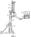
- a three dimensional measuring system for use in the present invention generally comprises a coordinate measuring machine (CMM) 10 composed of a manually operated multijointed arm 12 and a support base or post 14, a controller or serial box 16 and a host computer 18. It will be appreciated that CMM 10 electronically communicates with serial box 16 which, in turn, electronically communicates with host computer 18.
- CMM coordinate measuring machine
- CMM 10 includes transducers (e.g., one transducer for each degree of freedom) which gather rotational positioning data and forward this basic data to serial box 16.
- Serial box 16 provides a reduction in the overall requirements of host computer 18 to handle certain complex calculations and provides certain preliminary data manipulations.
- Basic transducer data is sent from CMM 10 to serial box 16.
- Serial box 16 then processes the raw transducer data on an ongoing basis and responds to the queries of the host computer with the desired three-dimensional positional or orientational information.
- all three components defining the three dimensional measuring system of this invention are mounted on either a fixed mounting surface using a rigid plate and/or a standard optical measurement instrument thread followed by mounting on a known and standard theodolite mobile stand, such as part no. MWS750 manufactured by Brunson.
- a mobile stand is characterized by a stable rolling platform with an extendable vertical tower and with common attachments and locking mechanisms.
- a commercially available CMM for use in the present invention is the METRECOM MODEL: IND-01 Coordinate Measuring Machine commercially available from FARO Technologies, Inc., Industrial Division, 125 Technology Park, Lake Mary, Florida 32746 may be employed.
- a CMM (e.g., as described above with reference to U.S. Patent Number 5,402,582, the METRECOM Model: IND-01, or other commercially available CMM) is used to measure the position of a probe which includes a device having any one of a plurality of geometric shapes which are designed to match features of a work piece such as the diameter (e.g., of a formed piece of tubing, such as an automobile exhaust pipe), these devices are referred to herein as "interference extensions" which may take whatever shape the application demands and are discussed more fully below.
- FIGURES 2A and 2B a standard CMM industrial arm is schematically depicted at 12.
- a standard known ball probe 264 has a ball which fits into a snap on fitting 300 (the geometric shape of the interference extension having a hole therethrough with concave side walls sufficient to "snap" onto the ball) which is integral with an interference extension or in the illustration, disk 302, of any appropriate size (sizes may range to any dimension imaginable but generally range in the .25" (6,35 mm) diameter to the 6" (152,4 mm) diameter range for the most commonly employed tubing or pipe formations).
- CMM arm 12 is clamped in the region central to the required tube.
- FIGURE 2A depicts a typical interference extension with its snap-on fitting.
- the snap-on fitting 300 is preferably configured as an integral element of interference disk 302. In accordance with the present invention, the method of tube fitting may be best explained by the following example as discussed hereinafter.
- a length of tubing is required to travel from one fitting to another fitting in an automobile engine compartment and is required to go around a number of existing obstructions and the diameter of the tubing required is a 1" (25,4 mm) O.D. (Outer diameter) tubing.
- Interference disk 302 represents the 1" (25,4 mm) diameter of the required tube.
- Snap-on fitting 300 allows the interference disk 302 to be oriented in any direction required.
- the interference extension simulates the cross section of any desired tube size be it round or otherwise.
- the required tube is a 1" (25,4 mm) tube, hence the 1" (25,4 mm) interference extension with its integral swivel attachment joint is mounted to the end of the probe on the CMM arm.
- the integral swivel attachment is used to provide a simple mechanical means of determining the X, Y and Z position of the center of the tube with respect to any obstructions, automatically compensating for the tube diameter.
- the tube fitter (operator) 250 takes the end of the CMM arm to which is attached a standard ball probe 264 where the interference disk 302 is mounted and initially places the interference extension on the starting feature 304 (shown as a plane) in FIGURES 4-6.
- a measurement is taken by simply pressing a button or switch on the end effector of the CMM arm. From this starting measurement, the first section that is required for this tube is a long straight section 306.
- a second point is taken by depressing the button or switch at a point near an obstruction to be traversed but far enough away that the interference disk 302 still will not contact the obstruction. This provides two points in space which are generally centrally located within the cross-section of the desired tube.
- the line connecting the two points forms the first straight section of the tube.
- the operator 250 moves the probe along the desired path that will traverse the obstacle.
- the second point and the third point together form a second straight section.
- the software of the invention is then capable of constructing a curve 308 for the tubing having a constant radius and which will not cause a kink in the tubing and which will join sections 306 and 310.
- the radius is generated by the computer after input of wall thickness, exterior dimension of tube, and the material thereof, by the operator or the operator may specify the fixed radius, if desired.
- a tight angle between the line segments defined above would make a constant radius very difficult to achieve thus increasing the potential for a bind in the tube.
- the points may be either locked in space or moveable in space.
- the points become one or the other by the technician telling the machine whether they are locked or not in any number of conventional ways of providing instructions.
- the significance of locked or unlocked points is that where points are unlocked the software will move the points by lengthening or shortening straight sections or by moving points in space until the two sequential sections do intersect were they to be extended.
- the ability of the software to move points eliminates the need for complex curves which are difficult to machine and to determine. By ensuring intersection of sequential sections of pipe only a simple fixed radius curve is necessary. Software steps for correcting non-intersecting sections are described below. If it is determined by the computer that a fixed radius bend is not possible to be maintained by using points, an error message will be generated.
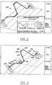
- the completed tubing profile is generally shown at 312 (see FIGURE 5) between starting feature 304 and end feature 314 (also shown as a plane as in feature 304).
- the rest of the fitted tube has sections that are alternately curved and straight to fill the space and at the same time avoid obstacles between feature 304 and feature 314.
- the curved sections and straight sections are designated 316, 318, 320, 322, 324, 326, 328, 330, 332 and 334, respectively from left to right in the FIGURES.
- Curved section 316 and straight section 318 are developed (tube fitted) by repeating the steps that created straight section 306 and curved section 308 as previously discussed until the entire tube profile between features 304 and 314 is completed.
- the computer screen presents the tube sections and curved or bent sections in real time as the tube profile is being created. Since the CMM is completely CAD-based, the computer model of the engine compartment of the example can be included in the display for completeness. The computer screen in accordance with the present invention also generates warnings and cautions for various problematic routing conditions.
- FIGURE 4 is one of many views possible of a tube fitting in process. Note the full graphics of the tube profile and the convenient drop down menus and selection icons as shown in FIGURES 4 and 5.
- Non-intersecting segments and segments which cannot be joined by a specified fixed radius curve are rectified by the computer as follows:
- intersection and curve mating can be sequential steps, concurrent steps or can be individually performed if conditions so require or if desired by the operator.
- the first step by the operator is to select "tube fitting" from the "tube” sub-menu of the "measure” pull down menu as the menu appears on the computer screen.
- the operator will then be prompted to measure a cylinder (straight tube) and a plane at one end of tube profile.
- the operator will be prompted to define two points on each segment of the tube and whether or not to "lock” those points in space. If a particular point is “locked”, this means that this particular point on the tube segment can not be moved from that particular position.
- both the second point of a first segment and the first point of the next (or second) segments are both "locked" in space, then the two segments will move towards each other in equal increments until they intersect and the distance between the two segments will be reported on the computer screen. Since the operator may not wish the segments to move as shown on the screen, the operator may optionally "undo" the last section and then add an extra straight section if needed or desired for design purposes. Once the operator is finished with the last segment (i.e., 334 in FIGURE 6), then the operator presses the back button at the end of the CMM arm to cancel the next segment. The computer screen will then read a prompt "are you done with the last segment?". The operator then presses the front button to indicate "yes".
- the tube fitting software automatically calculates the pull/turn/bend specifications as well as the straight section intersections for purposes of analysis and manufacture. At this point, that is, with all measurements completed, the operator is prompted to key in the tube diameter and bend radius, if not already done.
- the X, Y, Z and pull/turn/bend data is displayed on the computer screen and printed out automatically.
- the software in accordance with the present invention is capable of generating data in a variety of formats for the many different bending machines. These formats include relative, absolute, clockwise and counter clockwise formats.
- the full CAD capabilities of the software allow for extremely clear perspective and multi-component presentations of the completed fitted tube.
- CMMs because of the need for different levels of accuracy required for various applications, there are a variety of known CMMs available. This is desirable since the lower the accuracy required, the less expensive is the CMM in general. CMMs currently are available that can measure to 12' (3,65 m) in diameter and range in accuracy between +/- .003" (0,0762 mm) to +/- .012" (0,3048 mm). These same CMMs can be used to inspect prototype tubing as part of the tube fitting process in accordance with the present invention. FIGURE 3 shows just such a CMM being used to inspect a section of automobile muffler pipe.
- the CAD based CMM software in accordance with the present invention is capable of providing standard tube, surface and prismatic inspection. Specifically, the CAD based capabilities have led to the development of the novel solution for tube and pipe fitting resulting in quick and accurate pipe fitting without the use of templates and additionally, at the same time, provide the tube manufacturing data without additional steps. As previously discussed, CMMs are available in sizes and with accuracies that are convenient for most known applications and the software in accordance with the present invention is designed for easy use with graphics, user interfaces and provides complete user prompting.
- the disk 302 would be fixedly attached to the end probe thus allowing the programmer to provide information to the computer of the exact location of exterior points of the tube to be generated. This is possible in this embodiment because the computer can be told exactly where the parameters are for the interference extension, that extension not being moveable relative to the handle. Thus, not only would the axis points be stored in memory, but the entire tube would be stored in memory. This may be desirable in some applications.
- the interference extension could remain mobile by providing a complex array of transducers at the ball end of the probe in printed circuit format to allow electrical connection of the extension with discrete points of the ball thus providing orientational information about the extension to the computer.
- two straight segments of tube would be created by three points as opposed to four.
- the computer would not need to move points to create an intersection because the point of the intersection would already have been digitized. However, it may be necessary to shorten the straight sections in order that a curve could be generated capable of joining those sections.
- the radius of the curve in this embodiment would be determined solely by the computer based upon diameter of the tube, thickness of the material of the tube and the angle made between the segments created by point 1 and point 2 and by point 2 and point 3. Where the angle between these segments is too severe for a curve to be constructed, the computer generates a message prompting the operator to create additional points to arrange a series of fixed radius curves which strung together create a complex curve. Because of the plurality of points employed in this embodiment, however, the complex curve is easier to manufacture as a plurality of simple fixed radius curves.
- the CMM is provided with reconfigured software in order to reverse engineer an existing pipe, the dimensions for which have been lost.
- the operator is prompted to click on three points around the outer diameter of the pipe in roughly even spacing and as close as reasonably possible to a cross section of the pipe or tube.
- the computer will calculate the center point of the pipe by triangulation. As the operator enters points in the triangulation pattern, the computer generates a three dimensional map of the pipe or tube which may be displayed in real time. This map, being fully digitized, may then be communicated to a manufactory for reproducing the subject pipe.
Landscapes
- Engineering & Computer Science (AREA)
- Physics & Mathematics (AREA)
- General Physics & Mathematics (AREA)
- Automation & Control Theory (AREA)
- Robotics (AREA)
- Length Measuring Devices With Unspecified Measuring Means (AREA)
- Bending Of Plates, Rods, And Pipes (AREA)
- A Measuring Device Byusing Mechanical Method (AREA)
Applications Claiming Priority (2)
| Application Number | Priority Date | Filing Date | Title |
|---|---|---|---|
| US600275 | 1996-02-09 | ||
| US08/600,275 US5768792A (en) | 1996-02-09 | 1996-02-09 | Method and apparatus for measuring and tube fitting |
Publications (3)
| Publication Number | Publication Date |
|---|---|
| EP0789289A2 true EP0789289A2 (fr) | 1997-08-13 |
| EP0789289A3 EP0789289A3 (fr) | 1998-10-21 |
| EP0789289B1 EP0789289B1 (fr) | 2003-01-08 |
Family
ID=24402984
Family Applications (1)
| Application Number | Title | Priority Date | Filing Date |
|---|---|---|---|
| EP97101889A Expired - Lifetime EP0789289B1 (fr) | 1996-02-09 | 1997-02-06 | Méthode pour concevoir ou produire des tubes coudés |
Country Status (5)
| Country | Link |
|---|---|
| US (1) | US5768792A (fr) |
| EP (1) | EP0789289B1 (fr) |
| JP (1) | JPH09295043A (fr) |
| CA (1) | CA2196236A1 (fr) |
| DE (1) | DE69718222D1 (fr) |
Cited By (7)
| Publication number | Priority date | Publication date | Assignee | Title |
|---|---|---|---|---|
| WO2003081485A1 (fr) * | 2002-03-20 | 2003-10-02 | Faro Technologies, Inc. | Systeme et procede de mesure de coordonnees |
| EP1690609A1 (fr) * | 1998-02-03 | 2006-08-16 | Kabushiki Kaisha Opton | Dispositif de cintrage |
| EP1472627A4 (fr) * | 2002-02-05 | 2007-05-23 | Gcc Inc | Systeme et procede de dessin et de production de tubes coudes |
| FR2922655A1 (fr) * | 2007-10-23 | 2009-04-24 | Thales Sa | Systeme de mesure d'une grandeur physique et de representation cartographique de ces mesures. |
| FR2933185A1 (fr) * | 2008-06-27 | 2010-01-01 | Movea Sa | Systeme et procede de determination d'informations representatives du mouvement d'une chaine articulee |
| CN104215204A (zh) * | 2014-06-07 | 2014-12-17 | 李晓波 | 蒸发器管板管孔自动定位及记录管理系统 |
| DE102015120380A1 (de) * | 2015-11-25 | 2017-06-01 | Dr. Ing. H.C. F. Porsche Aktiengesellschaft | Verfahren zum Konstruieren und/oder Herstellen eines Fluidleitungssystems in einem Kraftfahrzeug |
Families Citing this family (97)
| Publication number | Priority date | Publication date | Assignee | Title |
|---|---|---|---|---|
| SE504830C2 (sv) * | 1996-01-09 | 1997-05-12 | Johansson Ab C E | Anordning för dimensionsbestämning av tredimensionella mätobjekt |
| US5926782A (en) * | 1996-11-12 | 1999-07-20 | Faro Technologies Inc | Convertible three dimensional coordinate measuring machine |
| JP3126114B2 (ja) * | 1997-11-12 | 2001-01-22 | 株式会社ミツトヨ | 非接触表面粗さ測定装置 |
| US5991704A (en) * | 1998-03-26 | 1999-11-23 | Chrysler Corporation | Flexible support with indicator device |
| US6253458B1 (en) * | 1998-12-08 | 2001-07-03 | Faro Technologies, Inc. | Adjustable counterbalance mechanism for a coordinate measurement machine |
| GB9923795D0 (en) * | 1999-10-09 | 1999-12-08 | British Aerospace | Micropositioning system |
| EP1136897A3 (fr) * | 2000-02-01 | 2004-09-22 | Faro Technologies | Méthode, système et milieu de stockage fournissant un programme exécutable à un système de mesure de coordonnées |
| US6606403B2 (en) * | 2000-05-04 | 2003-08-12 | Daniel Freifeld | Repetitive inspection system with intelligent tools |
| US6519860B1 (en) * | 2000-10-19 | 2003-02-18 | Sandia Corporation | Position feedback control system |
| US6668466B1 (en) * | 2000-10-19 | 2003-12-30 | Sandia Corporation | Highly accurate articulated coordinate measuring machine |
| CN100523709C (zh) * | 2002-02-14 | 2009-08-05 | Faro科技有限公司 | 带有铰接臂的便携式坐标测量机 |
| USRE42082E1 (en) | 2002-02-14 | 2011-02-01 | Faro Technologies, Inc. | Method and apparatus for improving measurement accuracy of a portable coordinate measurement machine |
| USD497815S1 (en) | 2002-02-14 | 2004-11-02 | Faro Technologies, Inc. | Portable coordinate measurement machine portion |
| US6952882B2 (en) * | 2002-02-14 | 2005-10-11 | Faro Technologies, Inc. | Portable coordinate measurement machine |
| US7073271B2 (en) * | 2002-02-14 | 2006-07-11 | Faro Technologies Inc. | Portable coordinate measurement machine |
| US7246030B2 (en) * | 2002-02-14 | 2007-07-17 | Faro Technologies, Inc. | Portable coordinate measurement machine with integrated line laser scanner |
| US6973734B2 (en) * | 2002-02-14 | 2005-12-13 | Faro Technologies, Inc. | Method for providing sensory feedback to the operator of a portable measurement machine |
| US7519493B2 (en) * | 2002-02-14 | 2009-04-14 | Faro Technologies, Inc. | Portable coordinate measurement machine with integrated line laser scanner |
| USD479544S1 (en) | 2002-02-14 | 2003-09-09 | Faro Technolgoies, Inc. | Portable coordinate measurement machine |
| US7881896B2 (en) | 2002-02-14 | 2011-02-01 | Faro Technologies, Inc. | Portable coordinate measurement machine with integrated line laser scanner |
| US6957496B2 (en) | 2002-02-14 | 2005-10-25 | Faro Technologies, Inc. | Method for improving measurement accuracy of a portable coordinate measurement machine |
| USD496595S1 (en) | 2002-02-14 | 2004-09-28 | Faro Technologies, Inc. | Portable coordinate measurement machine portion |
| USD505144S1 (en) * | 2002-02-14 | 2005-05-17 | Faro Technologies, Inc. | Laser scanner for a portable coordinate measurement machine |
| USD491210S1 (en) | 2003-02-13 | 2004-06-08 | Faro Technologies, Inc. | Probe for a portable coordinate measurement machine |
| US7693325B2 (en) | 2004-01-14 | 2010-04-06 | Hexagon Metrology, Inc. | Transprojection of geometry data |
| US7152456B2 (en) | 2004-01-14 | 2006-12-26 | Romer Incorporated | Automated robotic measuring system |
| KR20060038525A (ko) * | 2004-10-30 | 2006-05-04 | 한국전력공사 | 3축 변위 계측장치 |
| US7525276B2 (en) * | 2005-09-13 | 2009-04-28 | Romer, Inc. | Vehicle having an articulator |
| US7568293B2 (en) * | 2006-05-01 | 2009-08-04 | Paul Ferrari | Sealed battery for coordinate measurement machine |
| US7805854B2 (en) | 2006-05-15 | 2010-10-05 | Hexagon Metrology, Inc. | Systems and methods for positioning and measuring objects using a CMM |
| JP5728769B2 (ja) | 2006-11-20 | 2015-06-03 | ヘキサゴン メトロロジー アクチボラゲット | 継ぎ手を改良された座標測定機 |
| US7624510B2 (en) * | 2006-12-22 | 2009-12-01 | Hexagon Metrology, Inc. | Joint axis for coordinate measurement machine |
| US7546689B2 (en) * | 2007-07-09 | 2009-06-16 | Hexagon Metrology Ab | Joint for coordinate measurement device |
| US7774949B2 (en) * | 2007-09-28 | 2010-08-17 | Hexagon Metrology Ab | Coordinate measurement machine |
| US8122610B2 (en) * | 2008-03-28 | 2012-02-28 | Hexagon Metrology, Inc. | Systems and methods for improved coordination acquisition member comprising calibration information |
| US7779548B2 (en) * | 2008-03-28 | 2010-08-24 | Hexagon Metrology, Inc. | Coordinate measuring machine with rotatable grip |
| EP2108917B1 (fr) * | 2008-04-07 | 2012-10-03 | Leica Geosystems AG | Machine de mesure de coordonnées avec bras articulé |
| USD599226S1 (en) | 2008-04-11 | 2009-09-01 | Hexagon Metrology, Inc. | Portable coordinate measurement machine |
| US7640674B2 (en) * | 2008-05-05 | 2010-01-05 | Hexagon Metrology, Inc. | Systems and methods for calibrating a portable coordinate measurement machine |
| US7908757B2 (en) * | 2008-10-16 | 2011-03-22 | Hexagon Metrology, Inc. | Articulating measuring arm with laser scanner |
| NL1036517C2 (nl) * | 2009-02-05 | 2010-08-10 | Holding Prodim Systems B V | Inrichting en werkwijze voor het uitzetten van contouren of werken en een meetinrichting en aanwijsinrichting ingericht voor gebruik hierbij. |
| DE102009015920B4 (de) | 2009-03-25 | 2014-11-20 | Faro Technologies, Inc. | Vorrichtung zum optischen Abtasten und Vermessen einer Umgebung |
| US9551575B2 (en) | 2009-03-25 | 2017-01-24 | Faro Technologies, Inc. | Laser scanner having a multi-color light source and real-time color receiver |
| EP2449353B1 (fr) * | 2009-06-30 | 2019-09-11 | Hexagon Technology Center GmbH | Système de bras articulé avec détection de vibration et procédé de fonctionnement correspondant |
| US20110112786A1 (en) | 2009-11-06 | 2011-05-12 | Hexagon Metrology Ab | Cmm with improved sensors |
| US9113023B2 (en) | 2009-11-20 | 2015-08-18 | Faro Technologies, Inc. | Three-dimensional scanner with spectroscopic energy detector |
| US9210288B2 (en) | 2009-11-20 | 2015-12-08 | Faro Technologies, Inc. | Three-dimensional scanner with dichroic beam splitters to capture a variety of signals |
| US9529083B2 (en) | 2009-11-20 | 2016-12-27 | Faro Technologies, Inc. | Three-dimensional scanner with enhanced spectroscopic energy detector |
| DE102009057101A1 (de) | 2009-11-20 | 2011-05-26 | Faro Technologies, Inc., Lake Mary | Vorrichtung zum optischen Abtasten und Vermessen einer Umgebung |
| US20110213247A1 (en) * | 2010-01-08 | 2011-09-01 | Hexagon Metrology, Inc. | Articulated arm with imaging device |
| US8630314B2 (en) * | 2010-01-11 | 2014-01-14 | Faro Technologies, Inc. | Method and apparatus for synchronizing measurements taken by multiple metrology devices |
| US9163922B2 (en) | 2010-01-20 | 2015-10-20 | Faro Technologies, Inc. | Coordinate measurement machine with distance meter and camera to determine dimensions within camera images |
| US8832954B2 (en) | 2010-01-20 | 2014-09-16 | Faro Technologies, Inc. | Coordinate measurement machines with removable accessories |
| US8677643B2 (en) | 2010-01-20 | 2014-03-25 | Faro Technologies, Inc. | Coordinate measurement machines with removable accessories |
| US9879976B2 (en) | 2010-01-20 | 2018-01-30 | Faro Technologies, Inc. | Articulated arm coordinate measurement machine that uses a 2D camera to determine 3D coordinates of smoothly continuous edge features |
| US20110178765A1 (en) * | 2010-01-20 | 2011-07-21 | Faro Technologies, Inc. | Multi-functional coordinate measurement machines |
| US9607239B2 (en) | 2010-01-20 | 2017-03-28 | Faro Technologies, Inc. | Articulated arm coordinate measurement machine having a 2D camera and method of obtaining 3D representations |
| US8898919B2 (en) | 2010-01-20 | 2014-12-02 | Faro Technologies, Inc. | Coordinate measurement machine with distance meter used to establish frame of reference |
| US9628775B2 (en) | 2010-01-20 | 2017-04-18 | Faro Technologies, Inc. | Articulated arm coordinate measurement machine having a 2D camera and method of obtaining 3D representations |
| US8875409B2 (en) | 2010-01-20 | 2014-11-04 | Faro Technologies, Inc. | Coordinate measurement machines with removable accessories |
| CN102947667A (zh) * | 2010-01-20 | 2013-02-27 | 法罗技术股份有限公司 | 具有可移除的附件装置的坐标测量机 |
| JP5306545B2 (ja) | 2010-01-20 | 2013-10-02 | ファロ テクノロジーズ インコーポレーテッド | 照明付きプローブ端を有する座標測定機および動作方法 |
| US8615893B2 (en) | 2010-01-20 | 2013-12-31 | Faro Technologies, Inc. | Portable articulated arm coordinate measuring machine having integrated software controls |
| USD643319S1 (en) | 2010-03-29 | 2011-08-16 | Hexagon Metrology Ab | Portable coordinate measurement machine |
| DE102010020925B4 (de) | 2010-05-10 | 2014-02-27 | Faro Technologies, Inc. | Verfahren zum optischen Abtasten und Vermessen einer Umgebung |
| US8127458B1 (en) | 2010-08-31 | 2012-03-06 | Hexagon Metrology, Inc. | Mounting apparatus for articulated arm laser scanner |
| WO2012033892A1 (fr) | 2010-09-08 | 2012-03-15 | Faro Technologies, Inc. | Dispositif de balayage laser ou dispositif de poursuite laser équipé d'un projecteur |
| USD659034S1 (en) | 2010-11-16 | 2012-05-08 | Faro Technologies, Inc. | Display for a measurement device |
| USD659032S1 (en) | 2010-11-16 | 2012-05-08 | Faro Technologies, Inc. | Laser measurement device |
| USD659033S1 (en) | 2010-11-16 | 2012-05-08 | Faro Technologies, Inc. | Handle for a measurement device |
| USD676309S1 (en) | 2010-11-16 | 2013-02-19 | Faro Technologies, Inc. | Base for a device |
| US9168654B2 (en) | 2010-11-16 | 2015-10-27 | Faro Technologies, Inc. | Coordinate measuring machines with dual layer arm |
| USD662427S1 (en) | 2010-11-16 | 2012-06-26 | Faro Technologies, Inc. | Measurement device |
| US9222771B2 (en) | 2011-10-17 | 2015-12-29 | Kla-Tencor Corp. | Acquisition of information for a construction site |
| US8763267B2 (en) | 2012-01-20 | 2014-07-01 | Hexagon Technology Center Gmbh | Locking counterbalance for a CMM |
| DE102012100609A1 (de) | 2012-01-25 | 2013-07-25 | Faro Technologies, Inc. | Vorrichtung zum optischen Abtasten und Vermessen einer Umgebung |
| US9069355B2 (en) | 2012-06-08 | 2015-06-30 | Hexagon Technology Center Gmbh | System and method for a wireless feature pack |
| EP2677270B1 (fr) * | 2012-06-22 | 2015-01-28 | Hexagon Technology Center GmbH | Bras articulé CMM |
| US8997362B2 (en) | 2012-07-17 | 2015-04-07 | Faro Technologies, Inc. | Portable articulated arm coordinate measuring machine with optical communications bus |
| US9513107B2 (en) | 2012-10-05 | 2016-12-06 | Faro Technologies, Inc. | Registration calculation between three-dimensional (3D) scans based on two-dimensional (2D) scan data from a 3D scanner |
| DE102012109481A1 (de) | 2012-10-05 | 2014-04-10 | Faro Technologies, Inc. | Vorrichtung zum optischen Abtasten und Vermessen einer Umgebung |
| US10067231B2 (en) | 2012-10-05 | 2018-09-04 | Faro Technologies, Inc. | Registration calculation of three-dimensional scanner data performed between scans based on measurements by two-dimensional scanner |
| US9250214B2 (en) | 2013-03-12 | 2016-02-02 | Hexagon Metrology, Inc. | CMM with flaw detection system |
| US9163921B2 (en) | 2013-12-18 | 2015-10-20 | Hexagon Metrology, Inc. | Ultra-portable articulated arm coordinate measurement machine |
| US9594250B2 (en) | 2013-12-18 | 2017-03-14 | Hexagon Metrology, Inc. | Ultra-portable coordinate measurement machine |
| US9759540B2 (en) | 2014-06-11 | 2017-09-12 | Hexagon Metrology, Inc. | Articulating CMM probe |
| CN107076551B (zh) | 2014-09-19 | 2021-02-02 | 海克斯康测量技术有限公司 | 多模式便携式坐标测量机 |
| DE102015122844A1 (de) | 2015-12-27 | 2017-06-29 | Faro Technologies, Inc. | 3D-Messvorrichtung mit Batteriepack |
| SG10201608757PA (en) * | 2016-10-19 | 2018-05-30 | Component Aerospace Singapore Pte Ltd | Method and apparatus for facilitating part verification |
| US10462444B2 (en) | 2017-04-17 | 2019-10-29 | Faro Technologies, Inc. | Three-dimensional inspection |
| GB201713556D0 (en) * | 2017-08-23 | 2017-10-04 | Paragon Inspection Ltd | Connector assembly evaluation tool and method of use |
| CN107389011A (zh) * | 2017-09-01 | 2017-11-24 | 凯里市浪金科技有限责任公司 | 一种可多方位测量的坐标测量装置 |
| US10625320B2 (en) * | 2017-12-20 | 2020-04-21 | Usui Co., Ltd. | Apparatus and method for bending a pipe and testing accuracy of a bent shape of the pipe |
| CN108097828B (zh) * | 2017-12-29 | 2023-06-06 | 浙江长兴和良智能装备有限公司 | 一种送料主轴装置及弯管机 |
| CN115769157B (zh) * | 2020-07-10 | 2025-06-13 | 发那科株式会社 | 轨道生成装置以及自动位置控制装置 |
| CN114216424B (zh) * | 2021-11-03 | 2024-06-14 | 中船澄西船舶修造有限公司 | 一种管子转角测量工装 |
| CN115325970A (zh) * | 2022-06-13 | 2022-11-11 | 中国第一汽车股份有限公司 | 用功能尺寸代替嵌合检具快速提升车身尺寸精度的方法、系统、设备、存储介质以及车辆 |
Citations (1)
| Publication number | Priority date | Publication date | Assignee | Title |
|---|---|---|---|---|
| US5402582A (en) | 1993-02-23 | 1995-04-04 | Faro Technologies Inc. | Three dimensional coordinate measuring apparatus |
Family Cites Families (13)
| Publication number | Priority date | Publication date | Assignee | Title |
|---|---|---|---|---|
| US2556381A (en) * | 1946-08-23 | 1951-06-12 | Dennis C White | Apparatus for measuring profiles and contours |
| US4146924A (en) * | 1975-09-22 | 1979-03-27 | Board Of Regents For Education Of The State Of Rhode Island | System for visually determining position in space and/or orientation in space and apparatus employing same |
| US4122608A (en) * | 1977-04-22 | 1978-10-31 | Teledyne Industries, Inc. | Tube feeler |
| US4122607A (en) * | 1976-12-22 | 1978-10-31 | Teledyne Industries, Inc. | Instrument for measuring preformed tubes |
| US4258474A (en) * | 1979-10-22 | 1981-03-31 | Teledyne Industries, Inc. | Method and apparatus for aiding measurement of preformed tubes |
| FR2468441A1 (fr) * | 1979-11-06 | 1981-05-08 | Adepa | Procede de reproduction ou de controle d'une piece a partir d'un modele, et dispositif pour sa mise en oeuvre |
| US4593476A (en) * | 1983-09-06 | 1986-06-10 | The Boeing Company | Computer aided adjustable tube checking fixture system |
| SU1548653A1 (ru) * | 1988-01-19 | 1990-03-07 | Предприятие П/Я Р-6719 | Устройство дл монтажа приспособлений дл контрол геометрических параметров гнутых труб |
| DE3900990A1 (de) * | 1989-01-12 | 1990-08-02 | Bundy Gmbh | Verfahren zum rechnergestuetzten auslegen des verlaufs, zum herstellen und einrichtung zum herstellen von raeumlich winklig gebogenen, kleinkalibrigen rohrleitungen, insbes. von kraftstoff- oder bremsleitungen im kraftfahrzeugbau |
| FI901153A7 (fi) * | 1990-03-07 | 1991-09-08 | Johannes Tokola | Foerfarande foer boejning av roer. |
| US5208995A (en) * | 1992-03-27 | 1993-05-11 | Mckendrick Blair T | Fixture gauge and method of manufacturing same |
| US5408754A (en) * | 1993-02-23 | 1995-04-25 | Faro Technologies, Inc. | Method and apparatus for measuring sleeping positions |
| US5400517A (en) * | 1993-07-13 | 1995-03-28 | Mckendrick; Blair T. | Locator assembly and method of making same |
-
1996
- 1996-02-09 US US08/600,275 patent/US5768792A/en not_active Expired - Lifetime
-
1997
- 1997-01-24 JP JP9011416A patent/JPH09295043A/ja active Pending
- 1997-01-29 CA CA002196236A patent/CA2196236A1/fr not_active Abandoned
- 1997-02-06 EP EP97101889A patent/EP0789289B1/fr not_active Expired - Lifetime
- 1997-02-06 DE DE69718222T patent/DE69718222D1/de not_active Expired - Lifetime
Patent Citations (1)
| Publication number | Priority date | Publication date | Assignee | Title |
|---|---|---|---|---|
| US5402582A (en) | 1993-02-23 | 1995-04-04 | Faro Technologies Inc. | Three dimensional coordinate measuring apparatus |
Cited By (11)
| Publication number | Priority date | Publication date | Assignee | Title |
|---|---|---|---|---|
| EP1690609A1 (fr) * | 1998-02-03 | 2006-08-16 | Kabushiki Kaisha Opton | Dispositif de cintrage |
| EP1472627A4 (fr) * | 2002-02-05 | 2007-05-23 | Gcc Inc | Systeme et procede de dessin et de production de tubes coudes |
| US7305274B2 (en) | 2002-02-05 | 2007-12-04 | Gcc, Inc. | System and method for drawing and manufacturing bent pipes |
| WO2003081485A1 (fr) * | 2002-03-20 | 2003-10-02 | Faro Technologies, Inc. | Systeme et procede de mesure de coordonnees |
| US6868359B2 (en) | 2002-03-20 | 2005-03-15 | Faro Technologies, Inc. | Method and system for CAD engine independence |
| FR2922655A1 (fr) * | 2007-10-23 | 2009-04-24 | Thales Sa | Systeme de mesure d'une grandeur physique et de representation cartographique de ces mesures. |
| WO2009053395A3 (fr) * | 2007-10-23 | 2009-07-16 | Thales Sa | Systeme de mesure d'une grandeur physique et de representation cartographique de ces mesures |
| FR2933185A1 (fr) * | 2008-06-27 | 2010-01-01 | Movea Sa | Systeme et procede de determination d'informations representatives du mouvement d'une chaine articulee |
| CN104215204A (zh) * | 2014-06-07 | 2014-12-17 | 李晓波 | 蒸发器管板管孔自动定位及记录管理系统 |
| DE102015120380A1 (de) * | 2015-11-25 | 2017-06-01 | Dr. Ing. H.C. F. Porsche Aktiengesellschaft | Verfahren zum Konstruieren und/oder Herstellen eines Fluidleitungssystems in einem Kraftfahrzeug |
| DE102015120380B4 (de) | 2015-11-25 | 2023-08-10 | Dr. Ing. H.C. F. Porsche Aktiengesellschaft | Verfahren zum Konstruieren und/oder Herstellen eines Fluidleitungssystems in einem Kraftfahrzeug |
Also Published As
| Publication number | Publication date |
|---|---|
| US5768792A (en) | 1998-06-23 |
| CA2196236A1 (fr) | 1997-08-10 |
| DE69718222D1 (de) | 2003-02-13 |
| EP0789289B1 (fr) | 2003-01-08 |
| EP0789289A3 (fr) | 1998-10-21 |
| JPH09295043A (ja) | 1997-11-18 |
Similar Documents
| Publication | Publication Date | Title |
|---|---|---|
| EP0789289B1 (fr) | Méthode pour concevoir ou produire des tubes coudés | |
| CA2463570C (fr) | Procede et systeme de visualisation de defauts superficiels | |
| US6073056A (en) | Method and system for building a data model of a physical part in a data format useful for and reproduction of the part | |
| US5337149A (en) | Computerized three dimensional data acquisition apparatus and method | |
| WO1993008449A1 (fr) | Mesure de la precision de machines a plusieurs axes | |
| Duffie et al. | CAD directed inspection and error analysis using surface patch databases | |
| Artkin | CMM machines and industrial applications | |
| JPH11142139A (ja) | 3次元自動計測装置用計測誤差補正方法 | |
| CN112113531B (zh) | 一种空间弯曲管件的数字化检测装置及检测方法 | |
| JP2539041B2 (ja) | 形状計測手順の教示方法 | |
| JP2539043B2 (ja) | 形状計測結果の表示方法 | |
| JP2002228044A (ja) | 3次元計測による既設配管と合せ配管との接合方法 | |
| JPH0321814A (ja) | 形状計測方法 | |
| Pahk et al. | Development of computer integrated system for error diagnosis of a CMM using calibrated mechanical artefacts | |
| JP2919127B2 (ja) | 三次元レーザ加工機のオフライン教示方法 | |
| CN204694211U (zh) | 智能计量检测单元的检测装置 | |
| CN120068330A (zh) | 基于虚拟现实的石油化工配管三维模拟设计系统 | |
| JPH0540409Y2 (fr) | ||
| JPH081380B2 (ja) | 対象物の計測方法 | |
| KR100219841B1 (ko) | 가공용 로봇 경로 자동 생성 방법 및 그 장치 | |
| JPH07182026A (ja) | 溶接予備処理位置の決定方法 | |
| JPH01112107A (ja) | 任意形状物体の倣い制御装置 | |
| JP2021081384A (ja) | 面歪評価装置、面歪評価方法、及び、プログラム | |
| CN121783063A (zh) | 弯管的几何参数评价方法 | |
| JPH1145107A (ja) | 曲面コーナー部仮想ピン角位置を算出する計測方法 |
Legal Events
| Date | Code | Title | Description |
|---|---|---|---|
| PUAI | Public reference made under article 153(3) epc to a published international application that has entered the european phase |
Free format text: ORIGINAL CODE: 0009012 |
|
| AK | Designated contracting states |
Kind code of ref document: A2 Designated state(s): DE FR GB IT |
|
| PUAL | Search report despatched |
Free format text: ORIGINAL CODE: 0009013 |
|
| AK | Designated contracting states |
Kind code of ref document: A3 Designated state(s): DE FR GB IT |
|
| 17P | Request for examination filed |
Effective date: 19990216 |
|
| 17Q | First examination report despatched |
Effective date: 20010618 |
|
| GRAG | Despatch of communication of intention to grant |
Free format text: ORIGINAL CODE: EPIDOS AGRA |
|
| GRAG | Despatch of communication of intention to grant |
Free format text: ORIGINAL CODE: EPIDOS AGRA |
|
| GRAH | Despatch of communication of intention to grant a patent |
Free format text: ORIGINAL CODE: EPIDOS IGRA |
|
| GRAH | Despatch of communication of intention to grant a patent |
Free format text: ORIGINAL CODE: EPIDOS IGRA |
|
| GRAA | (expected) grant |
Free format text: ORIGINAL CODE: 0009210 |
|
| AK | Designated contracting states |
Kind code of ref document: B1 Designated state(s): DE FR GB IT |
|
| PG25 | Lapsed in a contracting state [announced via postgrant information from national office to epo] |
Ref country code: IT Free format text: LAPSE BECAUSE OF FAILURE TO SUBMIT A TRANSLATION OF THE DESCRIPTION OR TO PAY THE FEE WITHIN THE PRE;WARNING: LAPSES OF ITALIAN PATENTS WITH EFFECTIVE DATE BEFORE 2007 MAY HAVE OCCURRED AT ANY TIME BEFORE 2007. THE CORRECT EFFECTIVE DATE MAY BE DIFFERENT FROM THE ONE RECORDED.SCRIBED TIME-LIMIT Effective date: 20030108 |
|
| REG | Reference to a national code |
Ref country code: GB Ref legal event code: FG4D |
|
| PGFP | Annual fee paid to national office [announced via postgrant information from national office to epo] |
Ref country code: FR Payment date: 20030131 Year of fee payment: 7 |
|
| PGFP | Annual fee paid to national office [announced via postgrant information from national office to epo] |
Ref country code: GB Payment date: 20030205 Year of fee payment: 7 |
|
| REF | Corresponds to: |
Ref document number: 69718222 Country of ref document: DE Date of ref document: 20030213 Kind code of ref document: P |
|
| PGFP | Annual fee paid to national office [announced via postgrant information from national office to epo] |
Ref country code: DE Payment date: 20030228 Year of fee payment: 7 |
|
| PG25 | Lapsed in a contracting state [announced via postgrant information from national office to epo] |
Ref country code: DE Free format text: LAPSE BECAUSE OF FAILURE TO SUBMIT A TRANSLATION OF THE DESCRIPTION OR TO PAY THE FEE WITHIN THE PRESCRIBED TIME-LIMIT Effective date: 20030409 |
|
| ET | Fr: translation filed | ||
| PLBE | No opposition filed within time limit |
Free format text: ORIGINAL CODE: 0009261 |
|
| STAA | Information on the status of an ep patent application or granted ep patent |
Free format text: STATUS: NO OPPOSITION FILED WITHIN TIME LIMIT |
|
| 26N | No opposition filed |
Effective date: 20031009 |
|
| PG25 | Lapsed in a contracting state [announced via postgrant information from national office to epo] |
Ref country code: GB Free format text: LAPSE BECAUSE OF NON-PAYMENT OF DUE FEES Effective date: 20040206 |
|
| GBPC | Gb: european patent ceased through non-payment of renewal fee |
Effective date: 20040206 |
|
| PG25 | Lapsed in a contracting state [announced via postgrant information from national office to epo] |
Ref country code: FR Free format text: LAPSE BECAUSE OF NON-PAYMENT OF DUE FEES Effective date: 20041029 |
|
| REG | Reference to a national code |
Ref country code: FR Ref legal event code: ST |