EP0789609B1 - Kerzenfiltervorrichtung mit spritzvorrichtung - Google Patents
Kerzenfiltervorrichtung mit spritzvorrichtung Download PDFInfo
- Publication number
- EP0789609B1 EP0789609B1 EP95936577A EP95936577A EP0789609B1 EP 0789609 B1 EP0789609 B1 EP 0789609B1 EP 95936577 A EP95936577 A EP 95936577A EP 95936577 A EP95936577 A EP 95936577A EP 0789609 B1 EP0789609 B1 EP 0789609B1
- Authority
- EP
- European Patent Office
- Prior art keywords
- spray
- filter
- tube filter
- arms
- tube
- Prior art date
- Legal status (The legal status is an assumption and is not a legal conclusion. Google has not performed a legal analysis and makes no representation as to the accuracy of the status listed.)
- Expired - Lifetime
Links
- 238000005507 spraying Methods 0.000 title abstract 7
- 235000013405 beer Nutrition 0.000 claims abstract description 12
- 238000001914 filtration Methods 0.000 claims abstract description 11
- 239000007921 spray Substances 0.000 claims description 85
- 239000007788 liquid Substances 0.000 claims description 6
- XLYOFNOQVPJJNP-UHFFFAOYSA-N water Substances O XLYOFNOQVPJJNP-UHFFFAOYSA-N 0.000 description 35
- 238000005192 partition Methods 0.000 description 12
- 238000004140 cleaning Methods 0.000 description 6
- 238000000034 method Methods 0.000 description 3
- 239000005909 Kieselgur Substances 0.000 description 2
- VYPSYNLAJGMNEJ-UHFFFAOYSA-N Silicium dioxide Chemical compound O=[Si]=O VYPSYNLAJGMNEJ-UHFFFAOYSA-N 0.000 description 2
- 238000004519 manufacturing process Methods 0.000 description 2
- 241001295925 Gegenes Species 0.000 description 1
- 208000012886 Vertigo Diseases 0.000 description 1
- 238000011109 contamination Methods 0.000 description 1
- 239000012065 filter cake Substances 0.000 description 1
- 238000011010 flushing procedure Methods 0.000 description 1
- 238000012423 maintenance Methods 0.000 description 1
- 238000011045 prefiltration Methods 0.000 description 1
- 239000008213 purified water Substances 0.000 description 1
Images

Classifications
-
- C—CHEMISTRY; METALLURGY
- C12—BIOCHEMISTRY; BEER; SPIRITS; WINE; VINEGAR; MICROBIOLOGY; ENZYMOLOGY; MUTATION OR GENETIC ENGINEERING
- C12H—PASTEURISATION, STERILISATION, PRESERVATION, PURIFICATION, CLARIFICATION OR AGEING OF ALCOHOLIC BEVERAGES; METHODS FOR ALTERING THE ALCOHOL CONTENT OF FERMENTED SOLUTIONS OR ALCOHOLIC BEVERAGES
- C12H1/00—Pasteurisation, sterilisation, preservation, purification, clarification, or ageing of alcoholic beverages
- C12H1/02—Pasteurisation, sterilisation, preservation, purification, clarification, or ageing of alcoholic beverages combined with removal of precipitate or added materials, e.g. adsorption material
- C12H1/06—Precipitation by physical means, e.g. by irradiation, vibrations
- C12H1/063—Separation by filtration
-
- B—PERFORMING OPERATIONS; TRANSPORTING
- B01—PHYSICAL OR CHEMICAL PROCESSES OR APPARATUS IN GENERAL
- B01D—SEPARATION
- B01D29/00—Filters with filtering elements stationary during filtration, e.g. pressure or suction filters, not covered by groups B01D24/00 - B01D27/00; Filtering elements therefor
- B01D29/11—Filters with filtering elements stationary during filtration, e.g. pressure or suction filters, not covered by groups B01D24/00 - B01D27/00; Filtering elements therefor with bag, cage, hose, tube, sleeve or like filtering elements
- B01D29/114—Filters with filtering elements stationary during filtration, e.g. pressure or suction filters, not covered by groups B01D24/00 - B01D27/00; Filtering elements therefor with bag, cage, hose, tube, sleeve or like filtering elements arranged for inward flow filtration
-
- B—PERFORMING OPERATIONS; TRANSPORTING
- B01—PHYSICAL OR CHEMICAL PROCESSES OR APPARATUS IN GENERAL
- B01D—SEPARATION
- B01D29/00—Filters with filtering elements stationary during filtration, e.g. pressure or suction filters, not covered by groups B01D24/00 - B01D27/00; Filtering elements therefor
- B01D29/50—Filters with filtering elements stationary during filtration, e.g. pressure or suction filters, not covered by groups B01D24/00 - B01D27/00; Filtering elements therefor with multiple filtering elements, characterised by their mutual disposition
- B01D29/52—Filters with filtering elements stationary during filtration, e.g. pressure or suction filters, not covered by groups B01D24/00 - B01D27/00; Filtering elements therefor with multiple filtering elements, characterised by their mutual disposition in parallel connection
-
- B—PERFORMING OPERATIONS; TRANSPORTING
- B01—PHYSICAL OR CHEMICAL PROCESSES OR APPARATUS IN GENERAL
- B01D—SEPARATION
- B01D29/00—Filters with filtering elements stationary during filtration, e.g. pressure or suction filters, not covered by groups B01D24/00 - B01D27/00; Filtering elements therefor
- B01D29/62—Regenerating the filter material in the filter
- B01D29/64—Regenerating the filter material in the filter by scrapers, brushes, nozzles, or the like, acting on the cake side of the filtering element
- B01D29/6438—Regenerating the filter material in the filter by scrapers, brushes, nozzles, or the like, acting on the cake side of the filtering element nozzles
- B01D29/6446—Regenerating the filter material in the filter by scrapers, brushes, nozzles, or the like, acting on the cake side of the filtering element nozzles with a rotary movement with respect to the filtering element
-
- B—PERFORMING OPERATIONS; TRANSPORTING
- B01—PHYSICAL OR CHEMICAL PROCESSES OR APPARATUS IN GENERAL
- B01D—SEPARATION
- B01D2201/00—Details relating to filtering apparatus
- B01D2201/04—Supports for the filtering elements
- B01D2201/043—Filter tubes connected to plates
- B01D2201/0446—Filter tubes connected to plates suspended from plates at the upper side of the filter elements
-
- B—PERFORMING OPERATIONS; TRANSPORTING
- B01—PHYSICAL OR CHEMICAL PROCESSES OR APPARATUS IN GENERAL
- B01D—SEPARATION
- B01D2201/00—Details relating to filtering apparatus
- B01D2201/28—Position of the filtering element
- B01D2201/287—Filtering elements with a vertical or inclined rotation or symmetry axis
Definitions
- the present invention relates to a candle filter device for beer filtration with a filter container.
- the use of such conventional candle filter devices is widely used for beer filtration.
- the conventional candle filter devices essentially have one cylindrical upper filter candle holder space on, in which a plurality of spaced apart, vertical arranged, rod-shaped filter candles arranged are. At the bottom, the candle-holding room is marked by a tapered outlet part continued. Over several access and Derivatives, especially in the lower and upper range of the filter container are provided depending on the stage of the process various flow media supplied and discharged. There are various process steps involved in beer filtration from. First of all the filter container is going from bottom to bottom filled with water at the top and vented the entire system. Then filter aids, e.g. Diatomaceous earth in the Filter container initiated, located on the filter cartridges washed up.
- filter aids e.g. Diatomaceous earth in the Filter container initiated, located on the filter cartridges washed up.
- a pre-filter phase the water is through Beer is pushed out of the filter container from the bottom upwards, with filter aids still being added. After that the actual filtration takes place, in which beer from bottom up with further addition of filter aids penetrates through the filter candles.
- a post-filter phase the beer is displaced from the filter container by water. Then the air in the filter container Displaced water. The dry filter cake is then blown off by the filter candles, after which an application of the Filter aid takes place via a lower derivative.
- the filter container is now filled with water several times filled and then emptied to remove the remaining contamination of filter aids to remove. This process is time-consuming and consumes a lot of water with yourself.
- US-A-4 834 883 shows a candle filter device which is suitable for beer filtration. It has a filter container, a filter candle receiving space in its upper part and below an outlet area. A partition in the upper part of the Filter candle receiving space, on the underside of filter candles are not explicitly shown, with such an arrangement, of course. Further it shows a feed line below the filter candles a spray arm that has an upward spray nozzle having.
- the present invention is therefore based on the object to provide a candle filter device that provides a reliable, easy, time and water saving cleaning enables.
- the device according to the invention has the advantage the water from the spray nozzles between the filter candles is injected onto the underside of the partition, so that remaining filter aid is reliably solved and is washed away with the water flowing downwards.
- This arrangement of the spray nozzles ensures that the water clears all the spaces between the filter candles detected. So the filter candles are through the up splashing against the partition and dripping down Purified water, including all residues of the filter aid, that have attached to the filter candles, loosened and washed down. Because that Water also splashes up in the area of the side walls and the side walls also run down this of the filter container cleaned in a reliable manner.
- the filter container is not complete must be filled with water, only small ones Splashes of water are required can be significant Water and thus production costs can be saved. Since the Spray arms can be rotated with the spray nozzles, the number the spray nozzles that is required to fit the filter cartridge sufficient to clean, to be minimized.
- the present Invention extends the supply line along the central axis of the filter container with two opposite Extend the spray arms radially outwards.
- This arrangement brings a balance of forces with it, so that it does not lead to any unilateral leverage comes. This results in a smooth, smooth and smooth rotation of the spray arms. The even load also reduces the wear, which in turn causes maintenance and repair costs be reduced to a minimum.
- This arrangement further allows the spray nozzles to be so on the opposite spray arms can be distributed that one spray nozzle each creates a spray circuit.
- At least one horizontally directed as the drive of the spray arms Opening on one long side of at least one spray arm provided that liquid through the supply line through the horizontal opening and so the Drives spray arms by recoil.
- the spray arms are inexpensive to implement like a water wheel through that from the horizontally directed Openings are driven by water.
- it is not complex mechanical or electrical drive necessary, which in turn is the manufacturing cost of the invention Candle filter device lowers.
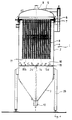
- Fig. 1 shows a first embodiment of the invention Candle filter device for beer filtration.
- the Candle filter device 1 is essentially made of a filter container 2 formed, which in turn a container lid 5, an adjoining substantially cylindrical one Filter candle receiving space 4 and in the further course down an essentially conical taper Has outlet area 3.
- At the top of the container lid 5 and below at the mouth of the outlet area 3 are central inlet and Outlet flanges 9, 10 attached.
- Laterally at the bottom of the cylindrical container section are uniform Rod or tubular feet distributed over the circumference 29 attached, which stand on the floor.
- a partition 6 provided with bores is arranged between the container lid 5 and the filter candle receiving space 4.
- a plurality of through openings 7 is a rod-shaped downward Candle 8 attached as a filter element.
- the filter container 2 is initially down further cylindrical.
- a feed line 14 for Cleaning water provided, two at the upper end equally long spray arms 15a and 15b, as in connection with Fig. 3 will be explained in more detail, are rotatably mounted.
- the both spray arms point upwards on their upper side Spray nozzles 16 on splashing water that over the Feed 14 in the arms 15a, b passes through the spray nozzles 16 can be injected between the filter candles 8.
- the drive for the spray arms 15a, b is at least one horizontal directed opening 19 on the same long side the spray arms 15 are provided so that liquid over the Lead 14 also passes through the opening 19, whereby the Spray arms 15a, b by the recoil force of the water in Rotation. It is also possible to use an electric motor to use as a drive.
- the spray nozzles 16 are along the entire length of the two Arms 15a and b distributed. As can be seen from Fig. 1 are the spray nozzles 16 the spaces between the individual Filter candles 8 opposite. As shown in Fig. 2, generate the spray nozzles 16 concentric when the spray arms 15a, b rotate Spray circles 20. From Fig. 2 it can be seen that the concentric circles due to the arrangement of the Spray nozzles 16, essentially between the filter candles 8 lie.
- the individual filter cartridges are offset from one another arranged in parallel rows. All filter cartridges can be used all around can be easily reached by splash water. The water from the spray nozzles 16 via the spaces 17, outside along the filter candles 8 to the bottom the partition 6 are injected to clean them.
- the Concentric spray circles 20 are arranged so that the Water essentially on the areas of the partition 6 splashes where no filter cartridges are arranged.
- the splashing water can then run down again along the filter candles 8 and filter aid residues detached from the partition and the candles carry down with. It also splashes Water from the outermost spray circuit 20a also between the filter container wall 40 and candles 8 up and running on them down so that the filter container wall 40 is cleaned.
- the number and arrangement of the spray nozzles 16 depends according to the number and arrangement of the filter cartridges, so that both between the filter candles 8 and between filter candles 8 and wall 40 water can be sprayed. It is particularly advantageous if the spray water with the help of a Control device from the nozzles 16 at intervals upwards is injected. So the splash water, in what deposits are solved, along the candles and the filter container wall run off before new spray water comes out of the spray nozzles 16 is injected. This results in an effective one and water-saving cleaning.
- Fig. 1 are the Spray nozzles distributed in such a way that in each case one spray nozzle 16 generates a spray circuit 20. So it creates on the spray arm 15a arranged spray nozzle 16a the smallest of the concentric Circles while the spray nozzle 16b that on the opposite Arm 15b is arranged, the next largest concentric circle. The following concentric Circles are then sequentially drawn from the spray nozzles 16c, d, e, f, g, h are formed, the neighboring spray circles corresponding spray nozzles on the opposite Spray arms 15a, b lie.
- the outermost spray nozzle 16h creates the spray circuit 20a that the filter cartridge assembly includes and between the outer filter cartridges 8 and the filter container wall 40 lies. It goes without saying also possible that per spray circuit both on the spray arm 15b and a spray nozzle 16 are provided on the spray arm 15a is.
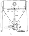
- Fig. 3 shows a partial section of a further embodiment of the present invention, which is essentially that of in Fig. 1 shown embodiment corresponds.
- the spray arm 15a is longer than the spray arm 15b.
- the spray arms 15a and b are rotatable via the collar bushing 24, which is at the upper end of the feeder 14 is attached, stored. Water flowing through the external supply 21 is fed to the feed 14, passes through the exit holes 26 in the feeder and passes over a through hole 25 of the sealed bushing inside the Spray arms 15a and b and can thus through the spray nozzles 16, as already detailed, sprayed to the filter candles 8 become.
- the supplied water splashes out of the horizontally directed opening 19 whereby the arms are driven.
- Fig. 3 is a another inlet 22 can be seen through which, for example, water, Beer or diatomaceous earth can be introduced.
- the above this incoming line 22 incoming liquid flows on the supply line 14 over into the manifold riser 27 and can by Exit holes 23 enter the filter container.
Landscapes
- Chemical & Material Sciences (AREA)
- Chemical Kinetics & Catalysis (AREA)
- Organic Chemistry (AREA)
- Health & Medical Sciences (AREA)
- Engineering & Computer Science (AREA)
- Genetics & Genomics (AREA)
- Food Science & Technology (AREA)
- Biochemistry (AREA)
- Bioinformatics & Cheminformatics (AREA)
- General Engineering & Computer Science (AREA)
- General Health & Medical Sciences (AREA)
- Toxicology (AREA)
- Life Sciences & Earth Sciences (AREA)
- Wood Science & Technology (AREA)
- Zoology (AREA)
- Cleaning By Liquid Or Steam (AREA)
- Filtration Of Liquid (AREA)
- Filtering Of Dispersed Particles In Gases (AREA)
- Details Or Accessories Of Spraying Plant Or Apparatus (AREA)
Abstract
Description
- einen Filterkerzenaufnahmeraum im oberen Teil des Filterbehälters und einen darunter angeordneten Auslaufraum;
- eine Trennwand im oberen Teil des Filterkerzenaufnahmeraumes, an deren Unterseite Filterkerzen angeordnet sind;
- eine Zuleitung, unterhalb der Filterkerzen gelengen, mit zumindest einem drehbar gelagerten Spritzarm, der nach oben gerichtete Spritzdüsen aufweist, wobei die Spritzdüsen so angeordnet sind, daß sie bei Drehung des Spritzarmes konzentrische Spritzkreise erzeugen, die im wesentlichen zwischen den Filterkerzen liegen, so daß beim Betrieb der Spritzdüsen die Spritzflüssigkeit im wesentlichen gegen die Bereiche der Unterseite der Trennwand gerichtet ist, an denen keine Filterkerzen befestigt sind, und
- einen Antrieb zum Drehen der Spritzarme.
- Fig. 1
- zeigt schematisch einen Längsschnitt durch einen Filterbehälter gemäß einem ersten Ausführungsbeispiel der vorliegenden Erfindung,
- Fig. 2
- zeigt einen Querschnitt durch eine Filterkerzenanordnung,
- Fig. 3
- zeigt teilweise einen Längsschnitt durch einen Filterbehälter gemäß einem zweiten Ausführungsbeispiel der vorliegenden Erfindung.
Claims (5)
- Kerzenfiltervorrichtung (1) für die Bierfiltration mit einem Filterbehälter (2), der folgendes umfaßt:einen Filterkerzenaufnahmeraum (4) im oberen Teil des Filterbehälters (2) und einen darunter angeordneten Auslaufraum (3);eine Trennwand (6) im oberen Teil des Filterkerzenaufnahmeraumes (4), an deren Unterseite Filterkerzen (8) angeordnet sind;eine Zuleitung (14), unterhalb der Filterkerzen (8) gelegen, mit zumindest einem drehbar gelagerten Spritzarm (15a, 15b), der nach oben gerichtete Spritzdüsen (16) aufweist, wobei die Spritzdüsen (16) so angeordnet sind, daß sie bei Drehung des Spritzarmes (15a, 15b) konzentrische Spritzkreise (20) erzeugen, die im wesentlichen Zwischen den Filterkerzen (8) liegen, so daß beim Betrieb der Spritzdüsen die Spritzflüssigkeit im wesentlichen gegen die Bereiche der Unterseite der Trennwand (6) gerichtet ist, an denen keine Filterkerzen befestigt sind, undeinen Antrieb (19) zum Drehen der Spritzarme (15a, 15b).
- Kerzenfiltervorrichtung nach Anspruch 1, dadurch gekennzeichnet, daß sich die Zuleitung (14) entlang der Mittelachse (18) des Filterbehälters erstreckt und sich zwei gegenüberliegende Spritzarme (15a,b) radial nach außen erstrecken.
- Kerzenfiltervorrichtung nach Anspruch 2, dadurch gekennzeichnet, daß die Spritzdüsen (16) auf den gegenüberliegenden Spritzarmen derart verteilt sind, daß jeweils eine Spritzdüse (16) einen Spritzkreis (20) erzeugt.
- Kerzenfiltervorrichtung nach mindestens einem der vorhergehenden Ansprüche, dadurch gekennzeichnet, daß ein Spritzarm (15a,b) länger als der gegenüberliegende Spritzarm ist.
- Kerzenfiltervorrichtung nach mindestens einem der vorhergehenden Ansprüche, dadurch gekennzeichnet, daß als Antrieb (19) der Spritzarme (15a,b) zumindest eine horizontal gerichtete Öffnung (19) auf einer Längsseite zumindest eines Spritzarmes (15a,b) derart vorgesehen ist, daß Flüssigkeit über die Zuleitung (14) durch die horizontal gerichtete Öffnung (19) tritt und so die Spritzarme (15a,b) durch Rückstoß antreibt.
Applications Claiming Priority (3)
| Application Number | Priority Date | Filing Date | Title |
|---|---|---|---|
| DE9417636U | 1994-11-03 | ||
| DE9417636U DE9417636U1 (de) | 1994-11-03 | 1994-11-03 | Kerzenfiltervorrichtung mit Spritzvorrichtung |
| PCT/EP1995/004275 WO1996014127A1 (de) | 1994-11-03 | 1995-10-31 | Kerzenfiltervorrichtung mit spritzvorrichtung |
Publications (2)
| Publication Number | Publication Date |
|---|---|
| EP0789609A1 EP0789609A1 (de) | 1997-08-20 |
| EP0789609B1 true EP0789609B1 (de) | 1999-01-07 |
Family
ID=6915659
Family Applications (1)
| Application Number | Title | Priority Date | Filing Date |
|---|---|---|---|
| EP95936577A Expired - Lifetime EP0789609B1 (de) | 1994-11-03 | 1995-10-31 | Kerzenfiltervorrichtung mit spritzvorrichtung |
Country Status (5)
| Country | Link |
|---|---|
| US (1) | US5858217A (de) |
| EP (1) | EP0789609B1 (de) |
| JP (1) | JP2934913B2 (de) |
| DE (2) | DE9417636U1 (de) |
| WO (1) | WO1996014127A1 (de) |
Families Citing this family (13)
| Publication number | Priority date | Publication date | Assignee | Title |
|---|---|---|---|---|
| DE59813622D1 (de) * | 1998-11-10 | 2006-08-10 | Filtrox Ag | Kerzenfilter für die Anschwemmfiltration von Getränken |
| ATE337064T1 (de) * | 2002-12-18 | 2006-09-15 | Filtrox Ag | Filter für die anschwemmfiltration und einlaufverteiler |
| US8992775B2 (en) * | 2006-10-31 | 2015-03-31 | Pentair Water Pool And Spa, Inc. | Diatomaceous earth filter apparatus and method |
| WO2008063159A2 (en) * | 2006-10-31 | 2008-05-29 | Pentair Water Pool And Spa, Inc. | Diatomaceous earth filter apparatus and method |
| CN101642643B (zh) * | 2009-08-22 | 2011-07-13 | 湖州德翔环境科技有限公司 | 水预处理高效便捷过滤器 |
| CN102698488A (zh) * | 2012-06-12 | 2012-10-03 | 蔡圣佳 | 一种自动卸渣过滤机 |
| JP2018530427A (ja) * | 2015-09-10 | 2018-10-18 | 1934612 オンタリオ インク.1934612 Ontario Inc. | 汚染された液体混合物中の固体粒子を脱水するための方法およびシステム |
| US10406458B1 (en) * | 2018-03-23 | 2019-09-10 | Blue Skies Global LLC | Regenerative media filtration |
| CN112105431B (zh) * | 2018-06-13 | 2023-02-21 | 嘉吉公司 | 液体排放过滤器及其用途 |
| WO2022015280A1 (en) * | 2020-07-13 | 2022-01-20 | Evoqua Water Technologies Llc | Regenerative media filter with flow diffuser |
| CA3241502A1 (en) * | 2022-01-14 | 2023-07-20 | Stefan Strasser | Candle filter device |
| US12215555B2 (en) * | 2023-03-21 | 2025-02-04 | Saudi Arabian Oil Company | Systems and methods for operating candle filters to recover glycols from drilling operations |
| CN117861293A (zh) * | 2023-12-28 | 2024-04-12 | 普瑞特机械制造股份有限公司 | 发酵槽自动抽黄水机构 |
Family Cites Families (8)
| Publication number | Priority date | Publication date | Assignee | Title |
|---|---|---|---|---|
| US2854091A (en) * | 1955-07-22 | 1958-09-30 | Research Corp | Apparatus for cleaning bag filters |
| US2854142A (en) * | 1956-07-18 | 1958-09-30 | Swimquip Inc | Filter |
| DE2606804C2 (de) * | 1976-02-20 | 1984-08-09 | Seitz Enzinger Noll Maschinenbau Ag, 6800 Mannheim | Verfahren und Vorrichtung zum Reinigen von Spaltfilterkerzen |
| US4834883A (en) * | 1987-12-14 | 1989-05-30 | David C. Lake | Filter cleaning apparatus |
| EP0324330B1 (de) * | 1988-01-11 | 1992-03-18 | VOEST-ALPINE INDUSTRIEANLAGENBAU GESELLSCHAFT m.b.H. | Vorrichtung zur Entnahme heisser Gasproben aus einem Reaktionsgefäss |
| FR2638659B1 (fr) * | 1988-11-07 | 1992-06-12 | Framatome Sa | Appareil de filtration comportant un dispositif de decolmatage par ultrasons et procede de decolmatage correspondant |
| IL94630A (en) * | 1990-06-06 | 1993-08-18 | Filtration Ltd Herzliya And Yt | Self-cleaning filter |
| JP3795101B2 (ja) * | 1994-06-24 | 2006-07-12 | サッポロビール株式会社 | 濾過装置及びその原液回収方法 |
-
1994
- 1994-11-03 DE DE9417636U patent/DE9417636U1/de not_active Expired - Lifetime
-
1995
- 1995-10-31 WO PCT/EP1995/004275 patent/WO1996014127A1/de not_active Ceased
- 1995-10-31 DE DE59504757T patent/DE59504757D1/de not_active Expired - Fee Related
- 1995-10-31 JP JP8515030A patent/JP2934913B2/ja not_active Expired - Lifetime
- 1995-10-31 EP EP95936577A patent/EP0789609B1/de not_active Expired - Lifetime
- 1995-10-31 US US08/836,160 patent/US5858217A/en not_active Expired - Fee Related
Also Published As
| Publication number | Publication date |
|---|---|
| EP0789609A1 (de) | 1997-08-20 |
| DE59504757D1 (de) | 1999-02-18 |
| WO1996014127A1 (de) | 1996-05-17 |
| US5858217A (en) | 1999-01-12 |
| DE9417636U1 (de) | 1995-02-02 |
| JPH10501461A (ja) | 1998-02-10 |
| JP2934913B2 (ja) | 1999-08-16 |
Similar Documents
| Publication | Publication Date | Title |
|---|---|---|
| EP0291538B1 (de) | Verfahren und Vorrichtung zum kontinuierlichen Filtrieren von Flüssigkeiten | |
| DE2621952C2 (de) | Vorrichtung zum Entplattieren und Reinigen von Plättchen oder Substraten | |
| DE69518046T2 (de) | Sprühmethode für Geschirrspüler und Vorrichtung für deren Durchführung | |
| EP0654294B1 (de) | Verfahren und Vorrichtung zum Ausfiltrieren und Rückspülen von Feststoff-Partikeln aus Flüssigkeiten | |
| DE102004001506B4 (de) | Tertiärfilter | |
| DE112012004992T5 (de) | Filtervorrichtung unter Verwendung druckbeaufschlagter Reversierreinigung mittels einer Filtertrommel | |
| DE9417636U1 (de) | Kerzenfiltervorrichtung mit Spritzvorrichtung | |
| DE2924901C2 (de) | ||
| EP0070589A2 (de) | Rückspüllbares Kerzenanschwemmfilter | |
| DE2640803C2 (de) | Lamellenseparator zur Sedimentierung | |
| EP0718022A1 (de) | Spaltfilter für Flüssigkeiten oder Gase | |
| EP4422845A1 (de) | Verfahren zum betreiben einer filtervorrichtung und filtervorrichtung | |
| DE3342689C2 (de) | Filtervorrichtung zum Entfernen von Verunreinigungen aus Flüssigkeiten, insbesondere aus Dispersionsfarben | |
| DE2849132C2 (de) | Spaltfilterelement | |
| DE3937378C2 (de) | ||
| EP0565857A1 (de) | Flüssigkeitsdruckfilter | |
| DE3621724A1 (de) | Vollautomatisches rueckspuelfilter fuer fluessige medien | |
| DE3340952C2 (de) | Filtereinheit | |
| DE2537513C3 (de) | Filtervorrichtung | |
| DE2165508A1 (de) | Zentrifuge zur kontinuierlichen trennung von feststoff-fluessigkeits-gemischen | |
| DE4029804C1 (en) | Cleaning powder metallurgical paint between runs - with soluble particles sepd. out by filter housing with partition from which bag filter element is suspended | |
| EP0789611B1 (de) | Kerzenfiltervorrichtung für die bierfiltration | |
| DE4111611A1 (de) | Rueckspuelfilter mit vorzugsweise mehreren filterkerzen | |
| DE2255184C3 (de) | Filter | |
| DE3818437A1 (de) | Filterbatterie |
Legal Events
| Date | Code | Title | Description |
|---|---|---|---|
| PUAI | Public reference made under article 153(3) epc to a published international application that has entered the european phase |
Free format text: ORIGINAL CODE: 0009012 |
|
| 17P | Request for examination filed |
Effective date: 19970502 |
|
| AK | Designated contracting states |
Kind code of ref document: A1 Designated state(s): BE CH DE GB IT LI |
|
| GRAG | Despatch of communication of intention to grant |
Free format text: ORIGINAL CODE: EPIDOS AGRA |
|
| 17Q | First examination report despatched |
Effective date: 19971229 |
|
| GRAG | Despatch of communication of intention to grant |
Free format text: ORIGINAL CODE: EPIDOS AGRA |
|
| GRAH | Despatch of communication of intention to grant a patent |
Free format text: ORIGINAL CODE: EPIDOS IGRA |
|
| GRAH | Despatch of communication of intention to grant a patent |
Free format text: ORIGINAL CODE: EPIDOS IGRA |
|
| GRAA | (expected) grant |
Free format text: ORIGINAL CODE: 0009210 |
|
| AK | Designated contracting states |
Kind code of ref document: B1 Designated state(s): BE CH DE GB IT LI |
|
| REG | Reference to a national code |
Ref country code: CH Ref legal event code: EP |
|
| GBT | Gb: translation of ep patent filed (gb section 77(6)(a)/1977) |
Effective date: 19990108 |
|
| REF | Corresponds to: |
Ref document number: 59504757 Country of ref document: DE Date of ref document: 19990218 |
|
| REG | Reference to a national code |
Ref country code: CH Ref legal event code: NV Representative=s name: BOVARD AG PATENTANWAELTE |
|
| ITF | It: translation for a ep patent filed | ||
| PLBE | No opposition filed within time limit |
Free format text: ORIGINAL CODE: 0009261 |
|
| STAA | Information on the status of an ep patent application or granted ep patent |
Free format text: STATUS: NO OPPOSITION FILED WITHIN TIME LIMIT |
|
| 26N | No opposition filed | ||
| REG | Reference to a national code |
Ref country code: GB Ref legal event code: IF02 |
|
| PGFP | Annual fee paid to national office [announced via postgrant information from national office to epo] |
Ref country code: BE Payment date: 20021022 Year of fee payment: 8 |
|
| PGFP | Annual fee paid to national office [announced via postgrant information from national office to epo] |
Ref country code: GB Payment date: 20021023 Year of fee payment: 8 |
|
| PGFP | Annual fee paid to national office [announced via postgrant information from national office to epo] |
Ref country code: CH Payment date: 20031024 Year of fee payment: 9 |
|
| PG25 | Lapsed in a contracting state [announced via postgrant information from national office to epo] |
Ref country code: GB Free format text: LAPSE BECAUSE OF NON-PAYMENT OF DUE FEES Effective date: 20031031 Ref country code: BE Free format text: LAPSE BECAUSE OF NON-PAYMENT OF DUE FEES Effective date: 20031031 |
|
| PGFP | Annual fee paid to national office [announced via postgrant information from national office to epo] |
Ref country code: DE Payment date: 20031128 Year of fee payment: 9 |
|
| BERE | Be: lapsed |
Owner name: ANTON *STEINECKER MASCHINENFABRIK G.M.B.H. Effective date: 20031031 |
|
| GBPC | Gb: european patent ceased through non-payment of renewal fee |
Effective date: 20031031 |
|
| PG25 | Lapsed in a contracting state [announced via postgrant information from national office to epo] |
Ref country code: LI Free format text: LAPSE BECAUSE OF NON-PAYMENT OF DUE FEES Effective date: 20041031 Ref country code: CH Free format text: LAPSE BECAUSE OF NON-PAYMENT OF DUE FEES Effective date: 20041031 |
|
| PG25 | Lapsed in a contracting state [announced via postgrant information from national office to epo] |
Ref country code: DE Free format text: LAPSE BECAUSE OF NON-PAYMENT OF DUE FEES Effective date: 20050503 |
|
| REG | Reference to a national code |
Ref country code: CH Ref legal event code: PL |
|
| PG25 | Lapsed in a contracting state [announced via postgrant information from national office to epo] |
Ref country code: IT Free format text: LAPSE BECAUSE OF NON-PAYMENT OF DUE FEES;WARNING: LAPSES OF ITALIAN PATENTS WITH EFFECTIVE DATE BEFORE 2007 MAY HAVE OCCURRED AT ANY TIME BEFORE 2007. THE CORRECT EFFECTIVE DATE MAY BE DIFFERENT FROM THE ONE RECORDED. Effective date: 20051031 |