EP0790123A2 - Stratifié comportant une couche métallique structurée et sa méthode de fabrication - Google Patents
Stratifié comportant une couche métallique structurée et sa méthode de fabrication Download PDFInfo
- Publication number
- EP0790123A2 EP0790123A2 EP97101732A EP97101732A EP0790123A2 EP 0790123 A2 EP0790123 A2 EP 0790123A2 EP 97101732 A EP97101732 A EP 97101732A EP 97101732 A EP97101732 A EP 97101732A EP 0790123 A2 EP0790123 A2 EP 0790123A2
- Authority
- EP
- European Patent Office
- Prior art keywords
- metal foil
- substrate
- laminate
- foil
- barrier layer
- Prior art date
- Legal status (The legal status is an assumption and is not a legal conclusion. Google has not performed a legal analysis and makes no representation as to the accuracy of the status listed.)
- Granted
Links
Images




Classifications
-
- B—PERFORMING OPERATIONS; TRANSPORTING
- B32—LAYERED PRODUCTS
- B32B—LAYERED PRODUCTS, i.e. PRODUCTS BUILT-UP OF STRATA OF FLAT OR NON-FLAT, e.g. CELLULAR OR HONEYCOMB, FORM
- B32B3/00—Layered products comprising a layer with external or internal discontinuities or unevennesses, or a layer of non-planar shape; Layered products comprising a layer having particular features of form
- B32B3/10—Layered products comprising a layer with external or internal discontinuities or unevennesses, or a layer of non-planar shape; Layered products comprising a layer having particular features of form characterised by a discontinuous layer, i.e. formed of separate pieces of material
- B32B3/18—Layered products comprising a layer with external or internal discontinuities or unevennesses, or a layer of non-planar shape; Layered products comprising a layer having particular features of form characterised by a discontinuous layer, i.e. formed of separate pieces of material characterised by an internal layer formed of separate pieces of material which are juxtaposed side-by-side
- B32B3/22—Layered products comprising a layer with external or internal discontinuities or unevennesses, or a layer of non-planar shape; Layered products comprising a layer having particular features of form characterised by a discontinuous layer, i.e. formed of separate pieces of material characterised by an internal layer formed of separate pieces of material which are juxtaposed side-by-side of spaced pieces
-
- B—PERFORMING OPERATIONS; TRANSPORTING
- B32—LAYERED PRODUCTS
- B32B—LAYERED PRODUCTS, i.e. PRODUCTS BUILT-UP OF STRATA OF FLAT OR NON-FLAT, e.g. CELLULAR OR HONEYCOMB, FORM
- B32B3/00—Layered products comprising a layer with external or internal discontinuities or unevennesses, or a layer of non-planar shape; Layered products comprising a layer having particular features of form
- B32B3/10—Layered products comprising a layer with external or internal discontinuities or unevennesses, or a layer of non-planar shape; Layered products comprising a layer having particular features of form characterised by a discontinuous layer, i.e. formed of separate pieces of material
- B32B3/18—Layered products comprising a layer with external or internal discontinuities or unevennesses, or a layer of non-planar shape; Layered products comprising a layer having particular features of form characterised by a discontinuous layer, i.e. formed of separate pieces of material characterised by an internal layer formed of separate pieces of material which are juxtaposed side-by-side
-
- B—PERFORMING OPERATIONS; TRANSPORTING
- B32—LAYERED PRODUCTS
- B32B—LAYERED PRODUCTS, i.e. PRODUCTS BUILT-UP OF STRATA OF FLAT OR NON-FLAT, e.g. CELLULAR OR HONEYCOMB, FORM
- B32B15/00—Layered products comprising a layer of metal
- B32B15/04—Layered products comprising a layer of metal comprising metal as the main or only constituent of a layer, which is next to another layer of the same or of a different material
-
- B—PERFORMING OPERATIONS; TRANSPORTING
- B32—LAYERED PRODUCTS
- B32B—LAYERED PRODUCTS, i.e. PRODUCTS BUILT-UP OF STRATA OF FLAT OR NON-FLAT, e.g. CELLULAR OR HONEYCOMB, FORM
- B32B15/00—Layered products comprising a layer of metal
- B32B15/04—Layered products comprising a layer of metal comprising metal as the main or only constituent of a layer, which is next to another layer of the same or of a different material
- B32B15/08—Layered products comprising a layer of metal comprising metal as the main or only constituent of a layer, which is next to another layer of the same or of a different material of synthetic resin
- B32B15/09—Layered products comprising a layer of metal comprising metal as the main or only constituent of a layer, which is next to another layer of the same or of a different material of synthetic resin comprising polyesters
-
- B—PERFORMING OPERATIONS; TRANSPORTING
- B32—LAYERED PRODUCTS
- B32B—LAYERED PRODUCTS, i.e. PRODUCTS BUILT-UP OF STRATA OF FLAT OR NON-FLAT, e.g. CELLULAR OR HONEYCOMB, FORM
- B32B15/00—Layered products comprising a layer of metal
- B32B15/04—Layered products comprising a layer of metal comprising metal as the main or only constituent of a layer, which is next to another layer of the same or of a different material
- B32B15/12—Layered products comprising a layer of metal comprising metal as the main or only constituent of a layer, which is next to another layer of the same or of a different material of paper or cardboard
-
- B—PERFORMING OPERATIONS; TRANSPORTING
- B32—LAYERED PRODUCTS
- B32B—LAYERED PRODUCTS, i.e. PRODUCTS BUILT-UP OF STRATA OF FLAT OR NON-FLAT, e.g. CELLULAR OR HONEYCOMB, FORM
- B32B15/00—Layered products comprising a layer of metal
- B32B15/20—Layered products comprising a layer of metal comprising aluminium or copper
-
- B—PERFORMING OPERATIONS; TRANSPORTING
- B32—LAYERED PRODUCTS
- B32B—LAYERED PRODUCTS, i.e. PRODUCTS BUILT-UP OF STRATA OF FLAT OR NON-FLAT, e.g. CELLULAR OR HONEYCOMB, FORM
- B32B27/00—Layered products comprising a layer of synthetic resin
- B32B27/36—Layered products comprising a layer of synthetic resin comprising polyesters
-
- B—PERFORMING OPERATIONS; TRANSPORTING
- B32—LAYERED PRODUCTS
- B32B—LAYERED PRODUCTS, i.e. PRODUCTS BUILT-UP OF STRATA OF FLAT OR NON-FLAT, e.g. CELLULAR OR HONEYCOMB, FORM
- B32B38/00—Ancillary operations in connection with laminating processes
- B32B38/10—Removing layers, or parts of layers, mechanically or chemically
-
- B—PERFORMING OPERATIONS; TRANSPORTING
- B32—LAYERED PRODUCTS
- B32B—LAYERED PRODUCTS, i.e. PRODUCTS BUILT-UP OF STRATA OF FLAT OR NON-FLAT, e.g. CELLULAR OR HONEYCOMB, FORM
- B32B7/00—Layered products characterised by the relation between layers; Layered products characterised by the relative orientation of features between layers, or by the relative values of a measurable parameter between layers, i.e. products comprising layers having different physical, chemical or physicochemical properties; Layered products characterised by the interconnection of layers
- B32B7/04—Interconnection of layers
- B32B7/12—Interconnection of layers using interposed adhesives or interposed materials with bonding properties
- B32B7/14—Interconnection of layers using interposed adhesives or interposed materials with bonding properties applied in spaced arrangements, e.g. in stripes
-
- B—PERFORMING OPERATIONS; TRANSPORTING
- B65—CONVEYING; PACKING; STORING; HANDLING THIN OR FILAMENTARY MATERIAL
- B65D—CONTAINERS FOR STORAGE OR TRANSPORT OF ARTICLES OR MATERIALS, e.g. BAGS, BARRELS, BOTTLES, BOXES, CANS, CARTONS, CRATES, DRUMS, JARS, TANKS, HOPPERS, FORWARDING CONTAINERS; ACCESSORIES, CLOSURES, OR FITTINGS THEREFOR; PACKAGING ELEMENTS; PACKAGES
- B65D81/00—Containers, packaging elements, or packages, for contents presenting particular transport or storage problems, or adapted to be used for non-packaging purposes after removal of contents
- B65D81/34—Containers, packaging elements, or packages, for contents presenting particular transport or storage problems, or adapted to be used for non-packaging purposes after removal of contents for packaging foodstuffs or other articles intended to be cooked or heated within the package
- B65D81/3446—Containers, packaging elements, or packages, for contents presenting particular transport or storage problems, or adapted to be used for non-packaging purposes after removal of contents for packaging foodstuffs or other articles intended to be cooked or heated within the package specially adapted to be heated by microwaves
-
- G—PHYSICS
- G08—SIGNALLING
- G08B—SIGNALLING SYSTEMS, e.g. PERSONAL CALLING SYSTEMS; ORDER TELEGRAPHS; ALARM SYSTEMS
- G08B13/00—Burglar, theft or intruder alarms
- G08B13/22—Electrical actuation
- G08B13/24—Electrical actuation by interference with electromagnetic field distribution
- G08B13/2402—Electronic Article Surveillance [EAS], i.e. systems using tags for detecting removal of a tagged item from a secure area, e.g. tags for detecting shoplifting
- G08B13/2428—Tag details
- G08B13/2437—Tag layered structure, processes for making layered tags
-
- G—PHYSICS
- G08—SIGNALLING
- G08B—SIGNALLING SYSTEMS, e.g. PERSONAL CALLING SYSTEMS; ORDER TELEGRAPHS; ALARM SYSTEMS
- G08B13/00—Burglar, theft or intruder alarms
- G08B13/22—Electrical actuation
- G08B13/24—Electrical actuation by interference with electromagnetic field distribution
- G08B13/2402—Electronic Article Surveillance [EAS], i.e. systems using tags for detecting removal of a tagged item from a secure area, e.g. tags for detecting shoplifting
- G08B13/2428—Tag details
- G08B13/2437—Tag layered structure, processes for making layered tags
- G08B13/244—Tag manufacturing, e.g. continuous manufacturing processes
-
- G—PHYSICS
- G08—SIGNALLING
- G08B—SIGNALLING SYSTEMS, e.g. PERSONAL CALLING SYSTEMS; ORDER TELEGRAPHS; ALARM SYSTEMS
- G08B13/00—Burglar, theft or intruder alarms
- G08B13/22—Electrical actuation
- G08B13/24—Electrical actuation by interference with electromagnetic field distribution
- G08B13/2402—Electronic Article Surveillance [EAS], i.e. systems using tags for detecting removal of a tagged item from a secure area, e.g. tags for detecting shoplifting
- G08B13/2428—Tag details
- G08B13/2437—Tag layered structure, processes for making layered tags
- G08B13/2445—Tag integrated into item to be protected, e.g. source tagging
-
- H—ELECTRICITY
- H05—ELECTRIC TECHNIQUES NOT OTHERWISE PROVIDED FOR
- H05K—PRINTED CIRCUITS; CASINGS OR CONSTRUCTIONAL DETAILS OF ELECTRIC APPARATUS; MANUFACTURE OF ASSEMBLAGES OF ELECTRICAL COMPONENTS
- H05K3/00—Apparatus or processes for manufacturing printed circuits
- H05K3/02—Apparatus or processes for manufacturing printed circuits in which the conductive material is applied to the surface of the insulating support and is thereafter removed from such areas of the surface which are not intended for current conducting or shielding
- H05K3/027—Apparatus or processes for manufacturing printed circuits in which the conductive material is applied to the surface of the insulating support and is thereafter removed from such areas of the surface which are not intended for current conducting or shielding the conductive material being removed by irradiation, e.g. by photons, alpha or beta particles
-
- B—PERFORMING OPERATIONS; TRANSPORTING
- B32—LAYERED PRODUCTS
- B32B—LAYERED PRODUCTS, i.e. PRODUCTS BUILT-UP OF STRATA OF FLAT OR NON-FLAT, e.g. CELLULAR OR HONEYCOMB, FORM
- B32B2310/00—Treatment by energy or chemical effects
- B32B2310/08—Treatment by energy or chemical effects by wave energy or particle radiation
- B32B2310/0806—Treatment by energy or chemical effects by wave energy or particle radiation using electromagnetic radiation
- B32B2310/0843—Treatment by energy or chemical effects by wave energy or particle radiation using electromagnetic radiation using laser
-
- B—PERFORMING OPERATIONS; TRANSPORTING
- B32—LAYERED PRODUCTS
- B32B—LAYERED PRODUCTS, i.e. PRODUCTS BUILT-UP OF STRATA OF FLAT OR NON-FLAT, e.g. CELLULAR OR HONEYCOMB, FORM
- B32B2367/00—Polyesters, e.g. PET, i.e. polyethylene terephthalate
-
- B—PERFORMING OPERATIONS; TRANSPORTING
- B32—LAYERED PRODUCTS
- B32B—LAYERED PRODUCTS, i.e. PRODUCTS BUILT-UP OF STRATA OF FLAT OR NON-FLAT, e.g. CELLULAR OR HONEYCOMB, FORM
- B32B2439/00—Containers; Receptacles
- B32B2439/70—Food packaging
-
- B—PERFORMING OPERATIONS; TRANSPORTING
- B65—CONVEYING; PACKING; STORING; HANDLING THIN OR FILAMENTARY MATERIAL
- B65D—CONTAINERS FOR STORAGE OR TRANSPORT OF ARTICLES OR MATERIALS, e.g. BAGS, BARRELS, BOTTLES, BOXES, CANS, CARTONS, CRATES, DRUMS, JARS, TANKS, HOPPERS, FORWARDING CONTAINERS; ACCESSORIES, CLOSURES, OR FITTINGS THEREFOR; PACKAGING ELEMENTS; PACKAGES
- B65D2211/00—Anti-theft means
-
- B—PERFORMING OPERATIONS; TRANSPORTING
- B65—CONVEYING; PACKING; STORING; HANDLING THIN OR FILAMENTARY MATERIAL
- B65D—CONTAINERS FOR STORAGE OR TRANSPORT OF ARTICLES OR MATERIALS, e.g. BAGS, BARRELS, BOTTLES, BOXES, CANS, CARTONS, CRATES, DRUMS, JARS, TANKS, HOPPERS, FORWARDING CONTAINERS; ACCESSORIES, CLOSURES, OR FITTINGS THEREFOR; PACKAGING ELEMENTS; PACKAGES
- B65D2581/00—Containers, packaging elements, or packages, for contents presenting particular transport or storage problems, or adapted to be used for non-packaging purposes after removal of contents
- B65D2581/34—Containers, packaging elements, or packages, for contents presenting particular transport or storage problems, or adapted to be used for non-packaging purposes after removal of contents for packaging foodstuffs or other articles intended to be cooked or heated within
- B65D2581/3437—Containers, packaging elements, or packages, for contents presenting particular transport or storage problems, or adapted to be used for non-packaging purposes after removal of contents for packaging foodstuffs or other articles intended to be cooked or heated within specially adapted to be heated by microwaves
- B65D2581/3439—Means for affecting the heating or cooking properties
- B65D2581/344—Geometry or shape factors influencing the microwave heating properties
-
- B—PERFORMING OPERATIONS; TRANSPORTING
- B65—CONVEYING; PACKING; STORING; HANDLING THIN OR FILAMENTARY MATERIAL
- B65D—CONTAINERS FOR STORAGE OR TRANSPORT OF ARTICLES OR MATERIALS, e.g. BAGS, BARRELS, BOTTLES, BOXES, CANS, CARTONS, CRATES, DRUMS, JARS, TANKS, HOPPERS, FORWARDING CONTAINERS; ACCESSORIES, CLOSURES, OR FITTINGS THEREFOR; PACKAGING ELEMENTS; PACKAGES
- B65D2581/00—Containers, packaging elements, or packages, for contents presenting particular transport or storage problems, or adapted to be used for non-packaging purposes after removal of contents
- B65D2581/34—Containers, packaging elements, or packages, for contents presenting particular transport or storage problems, or adapted to be used for non-packaging purposes after removal of contents for packaging foodstuffs or other articles intended to be cooked or heated within
- B65D2581/3437—Containers, packaging elements, or packages, for contents presenting particular transport or storage problems, or adapted to be used for non-packaging purposes after removal of contents for packaging foodstuffs or other articles intended to be cooked or heated within specially adapted to be heated by microwaves
- B65D2581/3463—Means for applying microwave reactive material to the package
- B65D2581/3467—Microwave reactive layer shaped by delamination, demetallizing or embossing
-
- B—PERFORMING OPERATIONS; TRANSPORTING
- B65—CONVEYING; PACKING; STORING; HANDLING THIN OR FILAMENTARY MATERIAL
- B65D—CONTAINERS FOR STORAGE OR TRANSPORT OF ARTICLES OR MATERIALS, e.g. BAGS, BARRELS, BOTTLES, BOXES, CANS, CARTONS, CRATES, DRUMS, JARS, TANKS, HOPPERS, FORWARDING CONTAINERS; ACCESSORIES, CLOSURES, OR FITTINGS THEREFOR; PACKAGING ELEMENTS; PACKAGES
- B65D2581/00—Containers, packaging elements, or packages, for contents presenting particular transport or storage problems, or adapted to be used for non-packaging purposes after removal of contents
- B65D2581/34—Containers, packaging elements, or packages, for contents presenting particular transport or storage problems, or adapted to be used for non-packaging purposes after removal of contents for packaging foodstuffs or other articles intended to be cooked or heated within
- B65D2581/3437—Containers, packaging elements, or packages, for contents presenting particular transport or storage problems, or adapted to be used for non-packaging purposes after removal of contents for packaging foodstuffs or other articles intended to be cooked or heated within specially adapted to be heated by microwaves
- B65D2581/3471—Microwave reactive substances present in the packaging material
- B65D2581/3472—Aluminium or compounds thereof
-
- B—PERFORMING OPERATIONS; TRANSPORTING
- B65—CONVEYING; PACKING; STORING; HANDLING THIN OR FILAMENTARY MATERIAL
- B65D—CONTAINERS FOR STORAGE OR TRANSPORT OF ARTICLES OR MATERIALS, e.g. BAGS, BARRELS, BOTTLES, BOXES, CANS, CARTONS, CRATES, DRUMS, JARS, TANKS, HOPPERS, FORWARDING CONTAINERS; ACCESSORIES, CLOSURES, OR FITTINGS THEREFOR; PACKAGING ELEMENTS; PACKAGES
- B65D2581/00—Containers, packaging elements, or packages, for contents presenting particular transport or storage problems, or adapted to be used for non-packaging purposes after removal of contents
- B65D2581/34—Containers, packaging elements, or packages, for contents presenting particular transport or storage problems, or adapted to be used for non-packaging purposes after removal of contents for packaging foodstuffs or other articles intended to be cooked or heated within
- B65D2581/3437—Containers, packaging elements, or packages, for contents presenting particular transport or storage problems, or adapted to be used for non-packaging purposes after removal of contents for packaging foodstuffs or other articles intended to be cooked or heated within specially adapted to be heated by microwaves
- B65D2581/3486—Dielectric characteristics of microwave reactive packaging
- B65D2581/3487—Reflection, Absorption and Transmission [RAT] properties of the microwave reactive package
Definitions
- the present invention relates generally to metal foil-containing laminates and to methods of making such laminates, more specifically to metal foil/substrate laminates useful, among other applications, for forming into food containers especially suitable for packaging foods intended to be heated in a microwave oven and, more particularly, to patterned metal foil/substrate laminates and to methods of making such laminates.
- a major disadvantage is the inability of the packaging to control the amount of microwave energy received by different areas of the food contained within the packaging.
- One particular problem is that the edges as well as the thinner areas of a food item become dried out and overcooked while the central or thicker areas may be barely cooked at all.
- Frozen food products particularly relatively large volume items and, more particularly, food items which have a thick center section and thinner end sections, are illustrative of food products which are likely to cook unevenly in available freezer-to-microwave oven packaging.
- frozen food products which consist of multiple different foodstuffs, each of which require different degrees of microwave heating, are food products in which some of the foodstuffs are likely to be overcooked while others are likely to be undercooked in available freezer-to-microwave packaging.
- Metal foil such as aluminum foil
- metal foil is opaque.
- U.S. Patent No. 3,615,713 and U.S. Patent No. 3,936,626 disclose microwave cooking apparatus comprising a tray having multiple and differently sized cutouts and a plurality of individual containers which are sized to be supported in the cutouts in the tray. Each container is designed to fully and properly cook the food product contained therewithin simultaneously with the food products in the other containers in order that a complete meal can be simultaneously prepared.
- the containers include varying amounts of aluminum foil for controlling the amount of microwave energy reaching each of the food products.
- containers which are intended to contain food products which require little or no heating, such as ice cream are formed of aluminum foil to fully shield the contents from microwave energy.
- Other containers are likewise formed of a microwave opaque material, such as aluminum foil, but have holes or openings formed therein to allow selected amounts of microwave radiation to penetrate the container and cook the food product therewithin within the prescribed time. The number and size of the holes is determined according to the normal cooking requirements of the food product within the container.
- U.S. Patent No. 4,351,997 discloses a food package comprising a tray including a bottom wall transparent to microwave radiation and a peripheral structure, including a peripheral wall and a peripheral rim extending outwardly from the peripheral wall at its top, wherein at least a portion of the peripheral structure incorporates a microwave opaque material, such as metallic foil, e.g., aluminum foil.
- the foil may advantageously be coated onto the peripheral wall substrate or laminated thereto.
- Food packages in which the metal foil is selectively located or patterned to shield selected portions of the tray from microwave energy contribute to uniform microwave cooking of the food product within the packages.
- a microwave heating tray including a cover having portions thereof formed of an aluminum foil laminate for shielding selected portions of the tray.
- Metal foil which has been patterned by selectively removing predetermined areas thereof is currently made for microwave packaging applications by caustic demetallizing of the metal foil in the predetermined areas.
- polyester film is vacuum metallized or laminated to aluminum foil and then selectively printed or coated with a patterned mask of caustic-resistant material over the areas of the aluminum foil to be protected. Thereafter, the masked laminate is sprayed with caustic or passed through a caustic bath wherein the unmasked areas of the aluminum foil are selectively removed by chemical reaction with the caustic.
- the resulting patterned foil/film laminate may be further laminated to a paper or paperboard substrate in conventional manner.
- the demetallizing process is slow, cumbersome and uneconomically costly. Equally important is that the chemical reaction generates hydrogen, which is difficult to deal with, and creates the need for aluminum recovery from the caustic bath.
- a cutting tool such as a rotary die or a laser
- a method of forming a patterned metal foil/substrate laminate comprising the steps of laminating a sheet of metal foil to a substrate by applying an adhesive between the foil and the substrate in a predetermined pattern which defines areas where adhesive is present and areas where no adhesive is present; cutting the metal foil in a pattern which corresponds to the boundaries of the adhesive-containing areas; and, removing the areas of metal foil which are not adhesively adhered to the substrate.
- the method includes the further step of laminating a sheet of barrier layer material, preferably polymer film, to the patterned metal foil layer of the patterned metal foil/substrate laminate.
- the metal foil is cut using a rotary die, desirably a machined rotary die, or a laser beam.
- the metal foil is unannealed aluminum foil
- the substrate is paperboard
- the polymer film is a polyester film.
- the present invention provides a patterned metal foil/substrate laminate wherein the pattern is formed by laminating a sheet of metal foil to a substrate by applying an adhesive between the metal foil and substrate in selected areas in a predetermined pattern, cutting the metal foil in a pattern that corresponds to the boundaries of the adhesive-applied areas and removing the unadhered areas of metal foil, whereby the metal foil pattern corresponds to the adhesive application pattern.
- the present invention provides a container for packaging food intended to be heated in a microwave oven and a method for making such a container according to which a patterned metal foil/substrate laminate is formed into a container wherein the foil-containing areas of the laminate form sections of the container which are opaque to microwave energy for preventing overcooking of foods in those sections of the container.
- a method for making a patterned metal foil/substrate laminate including the steps of laminating a sheet of metal foil to a substrate by applying an adhesive between the foil and the substrate and irradiating the metal foil in a predetermined pattern with a laser beam to vaporize the irradiated areas of the metal foil.
- the metal foil is aluminum foil and the substrate is paper or paperboard.
- the method may include the further step of laminating a sheet of barrier layer material, preferably polyester film, to the patterned metal foil layer of the patterned metal foil/substrate laminate.
- FIGURE 1 is a diagrammatic representation of a laminate including a patterned metal foil formed in accordance with the present invention.
- FIGURE 2 is a schematic representation of a first method of making patterned metal foil laminates in accordance with the present invention.
- FIGURE 3 is a schematic representation of a second method of making patterned metal foil laminates in accordance with the present invention.
- FIGURE 4 is a diagrammatic representation of a laminate including a patterned metal foil formed in accordance with the present invention.
- FIGURE 5 is a plan view of a blank for a container for packaging food intended for heating in a microwave oven, including one illustrative embodiment of patterned microwave packaging in accordance with the present invention.
- FIGURE 6 is a plan view of another blank for a container for packaging food intended for heating in a microwave oven, including a second illustrative embodiment of patterned microwave packaging in accordance with the present invention.
- FIGURE 7 is a plan view of still another blank for a container for packaging food intended for heating in a microwave oven, including a third illustrative embodiment of patterned microwave packaging in accordance with the present invention.
- FIGURE 8 is a schematic representation of a third method of making patterned metal foil laminates in accordance with the present invention.
- FIGURE 9 is a schematic representation of a fourth method of making patterned metal foil laminates in accordance with the present invention.
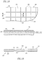
- FIGURE 10 is a fragmentary top plan view of one form of the patterned metal foil laminate made in accordance with the present invention which comprises a plurality of metal foil islands separated by dielectric substrate gaps.
- FIGURE 11 is an enlarged sectional view taken along line 11-11 in FIGURE 10.
- FIGURE 12 is a graphical representation of the relationship between gap separation and island center-to-center spacing for water spaced more than the gap separation distance from an island grid.
- FIGURE 13 is a graphical representation of the relationship between gap separation and island center-to-center spacing for meat spaced more than the gap separation distance from an island grid.
- FIGURE 14 is a graphical representation of the relationship between gap separation and island center-to-center spacing for bread spaced more than the gap separation distance from an island grid.
- FIGURE 15 is a graphical representation of the relationship between gap separation and island center-to-center spacing for water positioned adjacent an island grid.
- FIGURE 16 is a graphical representation of the relationship between gap separation and island center-to-center spacing for meat positioned adjacent an island grid.
- FIGURE 17 is a graphical representation of the relationship between gap separation and island center-to-center spacing for bread positioned adjacent an island grid.
- FIGURE 18 is a sectional view of a typical resonant circuit containing electronic surveillance tag made by a method of the present invention.
- Most commercially available packaging for food products intended to be cooked by microwave energy has the overall configuration of a three dimensional rectangular solid, the food product being contained within the walls. This configuration is easily formed from flat two dimensional blanks made of paperboard and the like, which can be folded or pressed to produce a three dimensional container of the desired size. Where the food product has a relatively large volume or pronounced thicker or thinner areas, the likely result of microwave cooking is that the edges and/or the thinner areas will be overcooked while the center and thicker areas will remain frozen or be barely cooked.
- the blanks may include portions formed of a substrate/metal foil laminate to define microwave transparent areas and microwave opaque areas of the packaging which can be positioned proximate to selected foods or portions of foods within the container to selectively shield these foods from microwave energy.
- the present invention provides metal foil/substrate laminates which are particularly useful for packaging foods intended for microwave heating and advantageous and economical methods of making such laminates.
- predetermined selected areas of the metal foil are removed, rendering those portions of the laminate transparent to microwave energy while the areas of the laminate where the metal foil is present remain opaque to microwave energy.
- a container can be formed from the laminate wherein the foil-containing areas of the laminate form sections of the container which are opaque to microwave energy for preventing overcooking of the food products in those sections of the container and encouraging uniform cooking of the food products.
- the metal foil patterns may be easily and conveniently customized to the food product and so shaped that undesirable heating areas in the food packaging are avoided.
- the microwave energy heating activity may be selectively reduced in different portions of the container to heat various portions of a food product at different rates or to different degrees.
- FIGURE 1 illustrates a patterned metal foil/substrate laminate 10 having areas which contain metal foil and areas from which the metal foil has been removed which was made in accordance with the method of the present invention.
- Laminate 10 includes a substrate 12, which may also function as one of the walls of the container comprising the food packaging.
- a metal foil layer 14 is adhered to substrate 12 and preferably positioned between the substrate and a barrier layer, such as a polymer film, 16 to which it is bonded.
- laminate 10 may be formed by applying adhesive in a predetermined pattern onto a substrate 12, adhering a metal foil sheet 14 to the substrate 12, cutting the metal foil sheet 14 in a pattern corresponding to the pattern of the applied adhesive, removing the unadhered metal foil and, for some applications, laminating a polymer film 16 over the adhered metal foil 14 into contact with the substrate and the foil.
- laminate 10 may be formed by applying adhesive onto a substrate 12, adhering a metal foil sheet 14 to the substrate 12, vaporizing metal foil in a predetermined pattern without damaging the substrate and, for some applications, laminating a polymer film 16 over the adhered metal foil 14 into contact with the substrate and the foil.
- Metal foil layer 14, shown in FIGURE 1 represents the portion of the applied metal foil sheet which remains following cutting and removing the unadhered portions thereof or following removal of metal foil by laser vaporization.
- the barrier layer 16 is preferably a heat tolerant and stable material which functions as a barrier to separate a food product in the container from the metal foil layer.
- the layer 16 must be microwave energy transparent and sufficiently stable at high temperatures when laminated to the metal foil so that it is suitable for contact with food at the temperatures reached while the food is being cooked in a microwave oven.
- Layer 16 may be formed from a wide variety of stable materials having barrier properties, such as polymeric film and paper, including polyesters, polyolefins, nylon, cellophane, paper and polysulfones. Polyester is the film material preferred for food containers because of its heat stability and surface smoothness.
- the thickness of the plastic film can preferably be about .0003 to .002 inches and, most desirably, about .0005 inches.
- the metal foil 14 is preferably aluminum foil, but may be any well known, thin, laminatable, microwave opaque metal foil, such as an aluminum alloy foil.
- the foil is a less malleable, i.e., more brittle, annealed or unannealed foil.
- An example of such an annealed foil is a relatively brittle aluminum alloy which is designed for diecutting.
- Such a foil is commercially available as Alumax 8145.
- particularly preferred for use is unannealed aluminum foil.
- the foil utilized in the laminate of the present invention has a thickness in the range of 0.0002 to 0.002 inches and, more preferably, is relatively thin having a thickness in the range of 0.0002 to 0.0006 inches.
- the substrate 12 is preferably a flexible material which is transparent to microwave energy and which has a relatively high insulating capacity and a heat stability sufficient to withstand cooking temperatures in a microwave oven.
- Suitable substrate materials include paper, coated and uncoated paperboard, plastic films such as polyester films, and composite materials, such as fiber/polymer composites.
- We preferred substrate materials are paper, coated and uncoated paperboard and polymer films.
- the patterned metal foil/substrate laminate 10 is advantageously made in accordance with the present invention in accordance with the method which is schematically illustrated in FIGURE 2 wherein adhesive is applied to the substrate-foil interface only in those areas of the laminate where microwave reflection is desired.
- the foil is cut, without significantly defacing, cutting or otherwise damaging the substrate, in a pattern that corresponds to the boundaries of the adhesive applied areas.
- the areas of the foil which are not adhesively adhered to the substrate are removed and, desirably, sent to a clean recycle stream.
- a barrier layer such as a polymer film layer, may be applied over the patterned metal foil layer to act as a barrier between the metal foil/substrate laminate and the food product.
- the resulting laminate comprising a substrate with patterned microwave reflecting foil areas adhesively laminated thereto, is particularly useful to form blanks for pressed or folded microwave trays and cartons.
- a sheet of substrate material 30, for example, paperboard is fed around feed roll 32.
- Adhesive is distributed from an adhesive reservoir 34 onto a patterned gravure roll 36 which transfers the adhesive in the predetermined pattern of the roll onto a sheet of metal foil 38 as the foil passes over laminating roll 40 into laminating contact with substrate sheet 30.
- adhesive may be applied using a flexographic rubber roll which has a raised pattern formed thereon.
- the resulting metal foil/substrate laminate passes between a rotary die 42 and anvil 44 where the metal foil layer is cut in a pattern that corresponds to the boundaries of the adhesive-applied areas without significantly defacing or degrading the substrate.
- the trim collection station comprises a combination rotating vacuum/pressure drum/vacuum hood or, simply, a vacuum hood, to remove the foil trim and scraps and blow the trim and scraps to a recycle station.
- a barrier layer such as a thin polymer film layer, e.g., a polyester film, may be applied over the patterned metal foil.
- Various techniques may be used to coat or laminate the polymer film 48 onto the metal foil.
- a polymer film having a heat sealable layer, such as amorphous polyester, on the surface thereof intended to contact the metal foil layer can be laminated to the foil layer by hot nip lamination.
- polymer film 48 passes over heated film laminating roll 50 to melt the heat sealable layer such that, when the melted layer is pressed into contact with the metal foil layer, the polymer film is heat sealed to the metal foil and substrate (in areas where the metal foil has been removed).
- Other well known laminating or coating techniques such as dry mount adhesive lamination, extrusion lamination, lamination using a solventless adhesive and extrusion coating, can likewise be utilized in the method of the present invention.
- Foil kiss rotary diecutting is one preferred method for cutting the foil in a pattern corresponding to the pattern of the applied adhesive.
- a problem encountered in diecutting aluminum foil/paperboard substrates is that aluminum foil is very malleable. It undergoes large out-of-plane shear strains without failing. In order to part the foil, a die has to penetrate deeply into the thick, soft board substrate. In the process, depending upon the die, the board may be unacceptably cut and damaged.
- machined rotary dies are the preferred cutting tool for diecutting aluminum foil. More particularly, machined rotary dies are typically sharp, even, precisely machined solid steel parts.
- Machined rotary dies are especially effective diecutting tools in that they are capable of clean, sharp, precise metal foil cutting without also cutting the underlying substrate.
- Rotary steel rule dies also produce satisfactory results in many applications. Serrated steel rule dies appear to produce superior results to straight steel rule dies.
- cutting is enhanced with steel rule dies when the substrate is corrugated paperboard, such as f-flute corrugated board, or when soil anvils are used during the diecutting.
- the soft anvil may be a conventional soft anvil, corrugated paperboard or the paperboard substrate which has been moisturized to provide the soft anvil.
- the metal foil is an unannealed aluminum foil. It is believed that the improved results observed with unannealed foils stems from the fact that such foils are more brittle and easier to die cut. For example, in one instance, particularly good results were obtained using a .0003 inch thick unannealed aluminum foil, commercially available as Alumax 1145 H19, laminated to a coated 18 pt. paperboard. No significant difference is noted when uncoated paperboard is substituted. When using unannealed metal foils, care should be exercised that lubricants used in the rolling of aluminum foil do not interfere with bonding the metal foil to the substrate. Unannealed foils still carry lubricating surface layers and these can interfere with bonding.
- surface lubricants on unannealed metal foil may be treated, e.g. by corona treatment or mild flame treatment sufficient to remove surface lubricants but insufficient to anneal the foil, to increase adhesion.
- special adhesives can be employed which form an effective bond even when the surface lubricants are present.
- laminating method described hereinabove can be practiced on various types of laminating equipment and all such equipment having the capability of performing the method of the present invention is contemplated for use in connection with the present invention.
- One suitable item of laminating equipment is a flexographic press with individual decks on which the various method steps can be performed.
- Another suitable item of laminating equipment utilizes a central impression drum, such as is shown schematically in FIGURE 3.
- the method which is schematically illustrated in FIGURE 3 is substantially identical to the method schematically illustrated in FIGURE 2 except that the pattern adhesive is applied to the substrate, rather than to the metal foil, prior to laminating the metal foil to the substrate and the metal foil is cut by a laser beam rather than by a rotary die.
- the adhesive is applied to the metal foil or the substrate.
- a sheet of substrate material 60 is fed between a central impression drum 62 and a feed roll 64.
- Adhesive is distributed from an adhesive reservoir 66 onto a patterned gravure roll 68 which transfers the adhesive in the predetermined pattern of the roll onto one face of the substrate sheet as it passes between support roll 70 and gravure roll 68.
- adhesive may be applied using a flexographic rubber roll which has the predetermined pattern formed thereon.
- a sheet of metal foil 72 is brought into laminating contact with the adhesive patterned substrate sheet as the metal foil sheet passes over laminating roll 74.
- the resulting metal foil/substrate laminate is moved past a laser cutting station 76 in which the metal foil is cut in a pattern that corresponds to the boundaries of the adhesive-applied areas without significantly defacing or degrading the substrate. It has been found that laser beam pattern cutting of metal foil is very precise and highly desirable, particularly where laser beam cutting is accomplished using a Nd:YAG laser. The laser can readily be adjusted for different patterns and different thickness metal foils merely by adjusting laser beam scan pattern and/or changing software.
- Laser beam cutting effectively burns away the metal foil while carefully preserving the substrate.
- the advantages of laser beam cutting offset the cost disadvantage and the inconvenience that, for large patterns, laser beam cutting is slower than die cutting and the laminate production line must be slowed.
- foil which is not adhesively adhered to the substrate is vacuum stripped in vacuum trim collection station 78 and sent to a clean metal foil recycle station (not shown).
- a barrier layer such as a thin polymer film layer, e.g., a polyester film, may be applied over the patterned metal foil.
- Various techniques may be used to coat or laminate the polymer film 80 onto the metal foil.
- a polymer film having a heat sealable layer e.g., an amorphous polyester layer, on the surface thereof intended to contact the metal foil can be passed over heated film laminating roll 82 to melt the heat sealable layer and pressed into contact with the metal foil to heat seal the polymer film to the metal foil and substrate by hot nip lamination.
- laminating or coating techniques such as dry mount adhesive lamination, extrusion lamination, lamination using a solventless adhesive and extrusion coating can be utilized.
- the goal sought to be achieved by the method of the present invention is the production of a laminate, like laminate 10 in FIGURE 1, including a patterned metal foil 14 that will reflect microwave energy to prevent overcooking of the food in the container adjacent to the areas where the foil is present.
- a laminate like laminate 10 in FIGURE 1, including a patterned metal foil 14 that will reflect microwave energy to prevent overcooking of the food in the container adjacent to the areas where the foil is present.
- selected areas of reduced microwave heating activity i.e., microwave reflective areas, can be positioned as required in a food package so that different areas of a food product can be heated at different rates and to different degrees.
- the barrier layer polymer film can be metallized with a thin metal foil by conventional techniques, such as vacuum metallizing, prior to laminating the polymer film to the patterned metal foil layer.
- laminate 90 includes metallized layer 92 positioned between the patterned metal foil layer 94/substrate 96 (in areas where the metal foil has been removed) and one surface of the barrier layer polymer film 98 and adhesively adhered to the patterned metal foil layer 94/substrate 96.
- the relative sizes of the layers shown are exaggerated for purposes of illustration.
- Laminate 90 has substantially all of the attributes of laminate 10 in enhancing uniform microwave cooking of food products by selectively shielding portions of the food products. In addition, however, in those areas of the laminate 90 where the patterned metal foil layer 94 has been removed, laminate 90 has the attributes of a microwave interactive layer. It will be appreciated that, when laminate 90 is formed into a food package for microwave cooking, appropriate selection of a metal foil pattern and selective positioning of the patterned metal foil permits not only selective shielding but also selective browning and crisping of the food product within the food package.
- tray blank 100 of FIGURE 5 The representation of one embodiment of a patterned metal foil/substrate laminate in accordance with the present invention for packaging foods intended for microwave heating is shown in the tray blank 100 of FIGURE 5.
- Tray blank 100 will ultimately be press formed to form a microwave heating container.
- the configuration of microwave reflective areas 102 and microwave transmissive areas 104 in the blank 100 is illustrative of an effective configuration for food products of a particular size, shape and dielectric constant.
- the portion of tray blank 100 which will form the bottom 106 when the blank 100 is press formed to form a tray contains no foil-containing areas.
- the portion of tray blank 100 which will form the side panels 108, 110 when the blank 100 is press formed to form a tray comprise substantially entirely foil-containing areas.
- Peripheral tray lip 112 is entirely free of metal foil to assure that there is no arcing to the microwave oven walls.
- the patterning of the metal foil and the resulting selective positioning of the foil containing areas 102 avoids excessive microwave heating of the food product in these areas and encourages uniform cooking.
- FIGURE 6 is an example of another tray blank 120 formed from the patterned metal foil/substrate laminate of the present invention.
- Tray blank 120 will ultimately be folded to form a microwave heating container.
- blank 120 includes foil-containing areas 122, which will reflect microwave energy, and areas 124 where the foil has been removed in accordance with the method of the present invention, which will transmit microwave energy.
- the peripheral tray lip 126 is entirely free of metal foil to assure that there is no arcing to the microwave oven walls. The resulting patterning and selective positioning of the foil containing areas 122 encourages uniform cooking of the food product.
- FIGURE 7 is yet another example of a tray blank 130 formed from the patterned metal foil/substrate laminate of the present invention.
- Tray blank 130 will ultimately be press formed to form a microwave heating container.
- blank 130 includes foil-containing areas 132, which will reflect microwave energy, and areas 134 where the foil has been removed in accordance with the method of the present invention, which will transmit microwave energy.
- the peripheral tray lip 136 is entirely free of metal foil to assure that there is no arcing to the microwave oven walls.
- the foil containing areas on what will form the bottom 138 when the blank 130 is press formed to form a tray include spaced, generally concentric rings.
- the portion of tray blank 130 which will form the side panels 140, 142 when the blank 130 is press formed comprise substantially entirely foil-containing areas.
- the resulting patterning and selective positioning of the foil containing areas 132 avoids overcooking of the food product in the foil-containing areas and encourages uniform cooking of the food product.
- each type of food product should be packaged in a container having a pattern of metal foil containing areas specifically designed for that type of food product.
- the present invention achieves this objective and facilitates the provision of patterned metal foil/substrate laminates specifically designed to produce the desired uniform cooking of a particular food product when that food product is heated in a microwave oven.
- the patterned metal foil/substrate laminate 10 may be advantageously made in accordance with the methods which are schematically illustrated in FIGURES 8 and 9 wherein adhesive is applied to the substrate-foil interface to form the laminate, after which the foil is removed in selected areas, in a predetermined pattern, by vaporization with a laser.
- a barrier layer such as a polymer film layer, may be applied over the patterned metal foil layer to act as a barrier between the metal foil/substrate laminate and the food product.
- the resulting laminate comprising a substrate with patterned microwave reflecting foil areas adhesively laminated thereto, is particularly useful to form blanks for pressed or folded microwave trays and cartons.
- a sheet of substrate material 30, for example, paperboard is fed around feed roll 32.
- Adhesive is distributed from an adhesive reservoir 34 onto a distribution roll 36a which transfers the adhesive onto a sheet of metal foil 38 as the foil passes over laminating roll 40 into laminating contact with substrate sheet 30.
- the resulting metal foil/substrate laminate moves past a laser cutting station 76 in which the metal foil is irradiated in a predetermined pattern without significantly defacing or degrading the substrate.
- irradiation is desirably accomplished using a Nd:YAG laser which is capable of ready adjustment for different patterns and different thickness metal foils.
- a barrier layer such as a thin polymer film layer, e.g., a polyester film, may be applied over the patterned metal foil using any of the various techniques hereinbefore described to coat or laminate the polymer film 48 onto the metal foil.
- FIGURE 9 Another suitable item of laminating equipment utilizes a central impression drum, such as is shown schematically in FIGURE 9.
- the method which is schematically illustrated in FIGURE 9 is substantially identical to the method schematically illustrated in FIGURE 8 except that the pattern adhesive is applied to the substrate, rather than to the metal foil.
- the adhesive is applied to the metal foil or the substrate.
- a sheet of substrate material 60 is fed between a central impression drum 62 and a feed roll 64.
- Adhesive is distributed from an adhesive reservoir 66 onto a distribution roll 68a which transfers the adhesive onto one face of the substrate sheet as it passes between support roll 70 and distribution roll 68a.
- a sheet of metal foil 72 is brought into laminating contact with the adhesive bearing substrate sheet as the metal foil sheet passes over laminating roll 74.
- the resulting metal foil/substrate laminate is moved past a laser cutting station 76 in which the metal foil is irradiated in a predetermined pattern without significantly defacing or degrading the substrate.
- a barrier layer 80 such as a thin polymer film layer, e.g., a polyester film, may be applied over the patterned metal foil using one of the various techniques hereinbefore described.
- an important objective of this invention is to provide a method for manufacturing inexpensive food packages that improve cooking uniformity in a microwave oven. This is accomplished by providing a package that is microwave opaque in some regions and microwave transparent in other regions. In this way, different areas of a food product can be heated at different rates and to different degrees.
- a patterned metal foil/substrate laminate in accordance with the present invention for packaging foods intended for microwave heating is formed with microwave transparent regions without the necessity for completely removing the metal foil in those regions demanding microwave transparency.
- the metal foil 202 of laminate 200 is diced into a plurality of conductive metal foil islands or patches 204 separated by gaps or strips 206.
- the metal foil 202 is aluminum foil having a thickness in the range of 0.0002 to 0.002 inches and, more preferably, a thickness in the range of 0.0002 to 0.0006 inches.
- the substrate 208 is, most desirably, paper or coated or uncoated paperboard.
- the resulting array of conductive foil islands are electrically separated from each other. Notwithstanding that, owing to their thickness, the metallic islands are reflective and do not transmit microwave energy therethrough, it has been found that judicious selection of the gap and island dimensions will cause the normally reflective aluminum foil to become substantially transparent to microwave energy.
- the object of the island-gap pattern is to locally deactivate, i.e., to functionally eliminate, an aluminum foil layer that would ordinarily be a microwave shield without completely removing the aluminum foil. According to the present invention, reflection and fringe field heating is minimized and thermal heating and attendant crisping and browning are negligible.
- a laminate can be made that preferentially passes microwave energy to hard-to-heat regions while maintaining shielding in easy-to-heat regions. This is significantly different than the gridding disclosed in U.S. Patent No. 4,230,924 - Brastad et al where the aluminum foil islands are intended to have a tangible influence on the food, i.e., to crispen or change the color of the food within the packaging.
- a method for making a patterned metal foil/substrate laminate for packaging foods intended for microwave heating comprises laminating a sheet of metal foil to a substrate by applying an adhesive between said metal foils and said substrate and irradiating said metal foil with a laser beam in a predetermined pattern to form a plurality of individual conductive foil islands electrically separated by gaps of dielectric substrate material.
- the islands may have regular geometric shapes, such as squares, or may be irregularly shaped or patterned. It has been found that a properly adjusted scanning laser beam from an infrared Nd:YAG laser will vaporize the aluminum foil of the laminate without damaging the paper or paperboard substrate.
- a plurality of square shaped conductive foil islands can be formed which are separated by relatively wide laser-made gaps of dielectric substrate material.
- the grid dimensions (island center-to-center spacing (W) and gap width (w)) necessary for deactivation of aluminum foil depend on the dielectric constant of the food to be placed in the package and the proximity of the grid to the food.
- Grids may be defined in terms of a gridding intensity quantity, A, expressed as Wln(2W/ ⁇ w). It will be appreciated from this expression that grids with smaller A's are more finely diced, i.e., smaller W's, or have greater separation or gaps between islands, i.e., larger w's.
- the electric field is concentrated in the gaps between islands and there is a volume of high microwave field intensity which extends a distance approximately equal to the gap separation, w, perpendicular to the grid.
- the reflectivity of a grid depends strongly on the dielectric constant of the matter, such as food, in this high field intensity volume.
- the grid is more reflective. Transmission of microwave energy is greatest when the grid is separated from the food surface by a distance much greater than the gap separation w. In such a case, the dielectric constant in the high field intensity volume is small.
- the necessary gridding intensity i.e., fineness or coarseness of grid, to transmit at least 90% of the energy which would have been transmitted in the absence of any grid, decreases as the food dielectric constant in the high field intensity volume decreases. Stated otherwise, it is easier to transparentize metal foil spaced away from high dielectric constant foods. Even well gridded foil near high dielectric constant foods reflects since the dielectric constant in the high field intensity volume is large. However, when the grid is immediately adjacent the food, the situation reverses. It is easier to transparentize metal foil near low dielectric constant foods.
- FIGURES 12 - 17 in each of which is plotted the values of w (island gap separation) in centimeters as a function of W (island center-to-center spacing) in centimeters necessary to achieve at least 90% of the energy transmission through the grid which would have been transmitted in the absence of any grid.
- FIGURES 12, 13 and 14 illustrate the relationship for three different foods, water, meat and bread, respectively, for the proximity condition where the food is positioned a distance greater than the gap separation, w, from the grid, i.e., outside of the high field intensity volume.
- FIGURES 15, 16 AND 17 illustrate the same relationship for the same foods, respectively, for the proximity condition where the food is positioned adjacent to the grid, i.e., within the high field intensity volume.
- the patterned metal foil/substrate laminates of the present invention are primarily useful in the production of packaging for food products intended for heating in a microwave oven for assuring the uniform cooking of the food product.
- these laminates have non-microwave cooking applications as well, such as applications in which laminates having customizable metal foil patterning is desired.
- patterned metal foil/substrate laminates of the present invention have widespread applications in electronic circuitry, particularly where the laminates are formed using laser beams for cutting the pattern.
- conductive circuitry has been manufactured either chemically, e.g., by caustic etching, or using laser beams, e.g., by depositing a very thin film metal layer, such as a metallized layer, on the surface of an insulating substrate, irradiating the metallized layer with a laser in a predetermined pattern for removing the metal layer where irradiated and, thereafter, forming a thicker conductive metal layer onto the remaining metallized layer.
- This multi step procedure was necessitated by the inability to irradiate, with a laser beam, metal layers having a thickness sufficient to exhibit satisfactory conductivity in a circuit without using sufficient laser output power that the underlying synthetic resin substrate becomes irreparably damaged. It will be appreciated that both caustic etching and multi-deposition laser forming processes are time consuming, cumbersome and costly.
- patterned metal foil/substrate laminates may be made and used for electrical circuitry by laminating a dielectric substrate to a metal foil layer and irradiating the foil layer with a laser beam in a predetermined pattern for removing the metal foil by vaporization where irradiated.
- the circuit includes extended areas which are functionally non-conductive, rather than use a laser beam to vaporize the entire extended area, it has been found to be advantageous to dice the area by cutting it into a plurality of individual conductive foil islands separated by gaps of dielectric material.
- a laser beam can be used to accomplish the dicing, as is disclosed hereinbefore in connection with microwave packaging applications.
- dicing can be accomplished by mechanically diecutting the gaps in the metal foil in accordance with the diecutting techniques hereinbefore disclosed.
- the metal foil utilized is preferably aluminum foil having a thickness in the range of 0.0002 to 0.002 inches, preferably 0.0002 to 0.0006 inches.
- the dielectric substrate is preferably a material, such as is hereinbefore disclosed in connection with microwave packaging applications, which has a relatively high insulating capacity. Most desirably, the substrate is selected from paper and coated and uncoated paperboard.
- the preferred laser is a Nd:YAG laser which can be readily adjusted for different patterns and different thickness metal foils.
- tags comprise inductive and capacitive elements arranged in series and supported on a dielectric substrate.
- the tags are typically used by attaching them to goods. When the customer presents the goods to pay for them, the tags are removed or deactivated.
- shoppers exiting the establishment are required to pass through radio-frequency transmitting and receiving units.
- a surveillance tag 220 embodying circuitry made in accordance with the present invention When a surveillance tag 220 embodying circuitry made in accordance with the present invention is subjected to a radio-frequency signal at the resonant frequency of its resonant circuitry an electronic anti-shoplifting system is activated which sounds an alarm to indicate that an item of merchandise bearing an intact tag is being carried from an exit of the establishment.
- Tag 220 comprises a patterned metal foil/substrate laminate 222 having areas which contain metal foil and areas from which the metal foil has been removed by laser beam vaporization.
- Laminate 222 includes a dielectric substrate 223, preferably formed of paper or paperboard, to which a spiral strip 224 is adhered on upper surface 226 and lower surface 228 of substrate 223.
- the spiral strip 224 functions as an inductor of the resonant circuit of tag 220.
- a capacitor 230 Connected in series with the inductive strip 224 is a capacitor 230 which is formed from two conductive plates 232 and 234 adhered, respectively, to upper surface 226 and lower surface 228.
- Laminate 222 is formed by adhesively adhering metal foil sheets to opposite surfaces of the substrate 223 and cutting the metal foil sheets using a laser beam into the patterns required to establish spiral strip 224 and capacitor plates 232 and 234 on the substrate 223.
- Spiral strips 224 and capacitor plates 232 and 234, shown in FIGURE 18, represent the portions of the applied metal foil sheets which remain following laser irradiation to vaporize the irradiated portions of the metal foil sheets.
Landscapes
- Engineering & Computer Science (AREA)
- Physics & Mathematics (AREA)
- General Physics & Mathematics (AREA)
- Computer Security & Cryptography (AREA)
- Automation & Control Theory (AREA)
- Electromagnetism (AREA)
- Manufacturing & Machinery (AREA)
- Mechanical Engineering (AREA)
- Life Sciences & Earth Sciences (AREA)
- Food Science & Technology (AREA)
- Microelectronics & Electronic Packaging (AREA)
- Laminated Bodies (AREA)
- Wrappers (AREA)
- Package Specialized In Special Use (AREA)
Applications Claiming Priority (4)
| Application Number | Priority Date | Filing Date | Title |
|---|---|---|---|
| US08/602,576 US5759422A (en) | 1996-02-14 | 1996-02-14 | Patterned metal foil laminate and method for making same |
| US602576 | 1996-02-14 | ||
| US08/784,287 US5800724A (en) | 1996-02-14 | 1997-01-16 | Patterned metal foil laminate and method for making same |
| US784287 | 1997-01-16 |
Publications (3)
| Publication Number | Publication Date |
|---|---|
| EP0790123A2 true EP0790123A2 (fr) | 1997-08-20 |
| EP0790123A3 EP0790123A3 (fr) | 1998-12-23 |
| EP0790123B1 EP0790123B1 (fr) | 2005-10-12 |
Family
ID=27084179
Family Applications (1)
| Application Number | Title | Priority Date | Filing Date |
|---|---|---|---|
| EP97101732A Expired - Lifetime EP0790123B1 (fr) | 1996-02-14 | 1997-02-04 | Stratifié comportant une couche métallique structurée et sa méthode de fabrication |
Country Status (7)
| Country | Link |
|---|---|
| US (1) | US5800724A (fr) |
| EP (1) | EP0790123B1 (fr) |
| JP (1) | JP3079164B2 (fr) |
| AU (1) | AU694385B2 (fr) |
| BR (1) | BR9700977A (fr) |
| CA (1) | CA2196861C (fr) |
| DE (1) | DE69734328T2 (fr) |
Cited By (16)
| Publication number | Priority date | Publication date | Assignee | Title |
|---|---|---|---|---|
| FR2781070A1 (fr) * | 1998-07-07 | 2000-01-14 | Itw De France | Dispositif reconnaissable radio-electriquement par une barriere antivol et procede pour sa preparation |
| EP1017033A3 (fr) * | 1998-12-14 | 2001-04-11 | Meto International GmbH | Elément pour la protection électronique d'articles et procédé de fabrication |
| GB2378582A (en) * | 2001-08-11 | 2003-02-12 | Ubinetics Ltd | A method of providing radio frequency screening for electronic components |
| WO2004045859A1 (fr) * | 2002-11-20 | 2004-06-03 | Leonhard Kurz Gmbh & Co. Kg | Procede pour produire un element de type feuille partiellement metallise |
| WO2005068321A3 (fr) * | 2004-01-19 | 2005-11-17 | Shieltronics B V | Methode de fabrication de parties de recipients, parties de recipients, methode de fabrication d'une feuille a couches multiples, feuille a couches multiples |
| WO2007045294A1 (fr) * | 2005-10-17 | 2007-04-26 | Leonhard Kurz Stiftung & Co. Kg | Corps multicouche et procede de realisation |
| WO2009118455A1 (fr) * | 2008-03-26 | 2009-10-01 | Tecnomar Oy | Procédé de fabrication d'une carte de circuit stratifiée |
| WO2010022813A1 (fr) * | 2008-08-27 | 2010-03-04 | Linden Gmbh & Co .Kg | Procédé de fabrication de panneaux et de capots argentés en plastique |
| EP2230192A3 (fr) * | 2006-04-27 | 2011-01-05 | Graphic Packaging International, Inc. | Emballage d'aliments réactif aux micro-ondes |
| ITRM20100387A1 (it) * | 2010-07-14 | 2012-01-15 | Prima S P A | Metodo di produzione di involucri per imballaggio alimentare dotati di dispositivo antifurto del tipo eas, linea di produzione per l'esecuzione del metodo e involucri così ottenuti |
| US9773203B2 (en) | 2014-12-26 | 2017-09-26 | Avery Dennison Retail Information Services, Llc | Creating antennas connected to printed chips by post processing with a laser or other cutting device |
| US9876265B2 (en) | 2010-06-14 | 2018-01-23 | Avery Dennison Retail Information Services, Llc | Foil laminate intermediate and method of manufacturing |
| US10186765B2 (en) | 2006-01-24 | 2019-01-22 | Avery Dennison Retail Information Services, Llc | Radio frequency (RF) antenna containing element and methods of making the same |
| US10237984B2 (en) | 2012-06-01 | 2019-03-19 | 3D-Micromac Ag | Method and installation for producing a multilayer element and multilayer element |
| CN109973932A (zh) * | 2017-12-15 | 2019-07-05 | 株式会社小糸制作所 | 树脂成型件及车辆用部件 |
| WO2023158393A1 (fr) * | 2022-02-16 | 2023-08-24 | Duran Doğan Basim Ve Ambalaj Sanayi̇ A.Ş. | Matériau d'emballage et son procédé de production |
Families Citing this family (196)
| Publication number | Priority date | Publication date | Assignee | Title |
|---|---|---|---|---|
| WO1999033649A1 (fr) * | 1997-12-31 | 1999-07-08 | Textron Systems Corporation | Feuilles metallisees, composites, et leurs procedes de fabrication |
| US6080958A (en) * | 1998-07-16 | 2000-06-27 | Ball Corporation | Method and apparatus for marking containers using laser light |
| US6706995B2 (en) * | 1998-07-16 | 2004-03-16 | Ball Corporation | Laser light marking of a container portion |
| US5994993A (en) * | 1998-07-31 | 1999-11-30 | Flexcon Company, Inc. | Fuse indicator label |
| US6355322B1 (en) | 1998-12-08 | 2002-03-12 | 3M Innovative Properties Company | Release liner incorporating a metal layer |
| LU90412B1 (fr) * | 1999-07-02 | 2001-01-03 | Cabinet Erman | Proc-d- d'enduction et produits issus du proc-d- |
| US6477404B1 (en) | 2000-03-01 | 2002-11-05 | Cardiac Pacemakers, Inc. | System and method for detection of pacing pulses within ECG signals |
| US6509588B1 (en) | 2000-11-03 | 2003-01-21 | Cardiac Pacemakers, Inc. | Method for interconnecting anodes and cathodes in a flat capacitor |
| US6833987B1 (en) | 2000-11-03 | 2004-12-21 | Cardiac Pacemakers, Inc. | Flat capacitor having an active case |
| US7456077B2 (en) | 2000-11-03 | 2008-11-25 | Cardiac Pacemakers, Inc. | Method for interconnecting anodes and cathodes in a flat capacitor |
| US6684102B1 (en) | 2000-11-03 | 2004-01-27 | Cardiac Pacemakers, Inc. | Implantable heart monitors having capacitors with endcap headers |
| US7107099B1 (en) | 2000-11-03 | 2006-09-12 | Cardiac Pacemakers, Inc. | Capacitor having a feedthrough assembly with a coupling member |
| US7355841B1 (en) | 2000-11-03 | 2008-04-08 | Cardiac Pacemakers, Inc. | Configurations and methods for making capacitor connections |
| US6571126B1 (en) | 2000-11-03 | 2003-05-27 | Cardiac Pacemakers, Inc. | Method of constructing a capacitor stack for a flat capacitor |
| US6522525B1 (en) | 2000-11-03 | 2003-02-18 | Cardiac Pacemakers, Inc. | Implantable heart monitors having flat capacitors with curved profiles |
| US6687118B1 (en) * | 2000-11-03 | 2004-02-03 | Cardiac Pacemakers, Inc. | Flat capacitor having staked foils and edge-connected connection members |
| US6699265B1 (en) | 2000-11-03 | 2004-03-02 | Cardiac Pacemakers, Inc. | Flat capacitor for an implantable medical device |
| US6456189B1 (en) | 2000-11-28 | 2002-09-24 | Ferraz Shawmut Inc. | Electrical fuse with indicator |
| US7022588B2 (en) * | 2001-10-09 | 2006-04-04 | Koninklijke Philips Electronics N.V. | Method of manufacturing an electronic component and electronic component obtained by means of said method |
| US7084769B2 (en) * | 2002-01-09 | 2006-08-01 | Vue Technology, Inc. | Intelligent station using multiple RF antennae and inventory control system and method incorporating same |
| US8339265B2 (en) | 2002-01-09 | 2012-12-25 | Sensormatic Electronics, Llc. | Method of assigning and deducing the location of articles detected by multiple RFID antennae |
| WO2003066435A2 (fr) | 2002-02-08 | 2003-08-14 | Graphic Packaging International, Inc. | Emballage isolant reagissant aux micro-ondes |
| US7323669B2 (en) * | 2002-02-08 | 2008-01-29 | Graphic Packaging International, Inc. | Microwave interactive flexible packaging |
| US20030175421A1 (en) * | 2002-03-13 | 2003-09-18 | Delphi Technologies, Inc. | Process for reducing contaminants on surfaces of die cast components |
| ES2396314T3 (es) | 2002-03-15 | 2013-02-20 | Graphic Packaging International, Inc. | Procedimiento y herramienta para conformar un recipiente que tiene una característica de moldeado por inyección |
| US7951479B2 (en) | 2005-05-11 | 2011-05-31 | Cardiac Pacemakers, Inc. | Method and apparatus for porous insulative film for insulating energy source layers |
| US7479349B2 (en) | 2002-12-31 | 2009-01-20 | Cardiac Pacemakers, Inc. | Batteries including a flat plate design |
| US20040158291A1 (en) * | 2003-02-07 | 2004-08-12 | Polkinghorne Jeannette C. | Implantable heart monitors having electrolytic capacitors with hydrogen-getting materials |
| DE10357525B3 (de) * | 2003-12-08 | 2005-02-24 | Lpkf Laser & Electronics Ag | Verfahren zum Aufbringen einer Deckschicht auf eine Basisschicht |
| US7611549B2 (en) * | 2003-12-22 | 2009-11-03 | Cardiac Pacemakers, Inc. | Magnetic stacking fixture for stacking electrodes |
| JP4327205B2 (ja) | 2004-02-09 | 2009-09-09 | グラフィック パッケージング インターナショナル インコーポレイテッド | 電子レンジ調理用パッケージ |
| US7384496B2 (en) * | 2004-02-23 | 2008-06-10 | Checkpoint Systems, Inc. | Security tag system for fabricating a tag including an integrated surface processing system |
| TWI288885B (en) * | 2004-06-24 | 2007-10-21 | Checkpoint Systems Inc | Die attach area cut-on-fly method and apparatus |
| US7180727B2 (en) | 2004-07-16 | 2007-02-20 | Cardiac Pacemakers, Inc. | Capacitor with single sided partial etch and stake |
| US7224575B2 (en) | 2004-07-16 | 2007-05-29 | Cardiac Pacemakers, Inc. | Method and apparatus for high voltage aluminum capacitor design |
| US7352560B2 (en) * | 2004-07-16 | 2008-04-01 | Cardiac Pacemakers, Inc. | Method and apparatus for interconnecting electrodes with partial titanium coating |
| US7982168B2 (en) * | 2004-08-25 | 2011-07-19 | Graphic Packaging International, Inc. | Absorbent microwave interactive packaging |
| CA2577150C (fr) | 2004-08-25 | 2010-02-23 | Graphic Packaging International, Inc. | Emballage interactif micro-ondes absorbant |
| US20060096978A1 (en) * | 2004-11-10 | 2006-05-11 | Graphic Packaging International, Inc | Insulated packages for microwaveable foods |
| US7514659B2 (en) * | 2005-01-14 | 2009-04-07 | Graphic Packaging International, Inc. | Package for browning and crisping dough-based foods in a microwave oven |
| AU2006218441B2 (en) * | 2005-03-03 | 2010-09-30 | Sensormatic Electronics, LLC | Apparatus for and method of using an intelligent network and RFID signal router |
| ATE497918T1 (de) * | 2005-04-11 | 2011-02-15 | Graphic Packaging Int Inc | In der mirkowelle erwärmbare, leicht zu öffnende lebensmittelverpackung |
| JP4950179B2 (ja) * | 2005-04-14 | 2012-06-13 | グラフィック パッケージング インターナショナル インコーポレイテッド | 熱的に活性可能なマイクロ波相互作用材料 |
| DE602006020282D1 (de) * | 2005-05-25 | 2011-04-07 | Graphic Packaging Int Inc | Mikrowellenverpackung für aus mehreren komponenten bestehende mahlzeiten |
| US20110204046A1 (en) * | 2005-05-25 | 2011-08-25 | Middleton Scott W | Microwave Heating Construct for Frozen Liquids and Other Items |
| EP1899243B1 (fr) | 2005-06-17 | 2019-09-18 | Graphic Packaging International, LLC | Suscepteurs d'equilibrage de contrainte et efficacite |
| JP4487875B2 (ja) * | 2005-07-20 | 2010-06-23 | セイコーエプソン株式会社 | 電子基板の製造方法及び電気光学装置の製造方法並びに電子機器の製造方法 |
| US20070184977A1 (en) * | 2005-07-29 | 2007-08-09 | Spiller Robert W | Microwavable construct with thermally responsive indicator |
| US7361872B2 (en) | 2005-08-16 | 2008-04-22 | Graphic Packaging International, Inc. | Variable serving size insulated packaging |
| BRPI0617109A2 (pt) * | 2005-08-29 | 2011-07-12 | Du Pont | conjuntos de susceptor, métodos para o aquecimento de um produto alimentìcio e estruturas de guia do campo |
| ES2387576T3 (es) | 2005-09-12 | 2012-09-26 | Graphic Packaging International, Inc. | Producto fabricado elevado para calentamiento mediante microondas |
| US8414962B2 (en) | 2005-10-28 | 2013-04-09 | The Penn State Research Foundation | Microcontact printed thin film capacitors |
| US7345262B2 (en) * | 2005-11-07 | 2008-03-18 | Graphic Packaging International, Inc. | Microwave interactive display package |
| US7982167B2 (en) | 2005-12-08 | 2011-07-19 | Graphic Packaging International, Inc. | Microwave food heating package with removable portion |
| US8367988B2 (en) * | 2005-12-19 | 2013-02-05 | E I Du Pont De Nemours And Company | Field director assembly having overheating protection |
| US8598500B2 (en) * | 2005-12-19 | 2013-12-03 | E I Du Pont De Nemours And Company | Arc-resistant microwave susceptor assembly |
| US8835822B2 (en) * | 2005-12-19 | 2014-09-16 | E I Du Pont De Nemours And Company | Field director assembly having arc-resistant conductive vanes |
| US8618453B2 (en) * | 2005-12-19 | 2013-12-31 | E I Du Pont De Nemours And Company | Microwave susceptor assembly having overheating protection |
| US8316156B2 (en) * | 2006-02-17 | 2012-11-20 | Intel-Ne, Inc. | Method and apparatus for interfacing device drivers to single multi-function adapter |
| WO2007103428A2 (fr) * | 2006-03-09 | 2007-09-13 | Graphic Packaging International, Inc. | Suscepteur muni d'un support a ouverture |
| EP1993928B1 (fr) | 2006-03-10 | 2011-05-11 | Graphic Packaging International, Inc. | Contenant a bande hyperfrequence interactive |
| US8124201B2 (en) * | 2006-03-10 | 2012-02-28 | Graphic Packaging International, Inc. | Injection-molded composite construct |
| WO2007126829A2 (fr) * | 2006-03-31 | 2007-11-08 | Graphic Packaging International, Inc. | Construction de support d'aliments |
| US8853601B2 (en) | 2006-03-31 | 2014-10-07 | Graphic Packaging International, Inc. | Microwavable construct for heating, browning, and crisping rounded food items |
| EP1840047B1 (fr) * | 2006-03-31 | 2009-08-26 | Graphic Packaging International, Inc. | Recipient, pour chauffer, rendre croustillant et pour brunir des aliments dans un four à micro-ondes |
| EP2013111B1 (fr) * | 2006-04-27 | 2010-06-23 | Graphic Packaging International, Inc. | Suscepteur a fusible multidirectionnel |
| US9205968B2 (en) | 2006-04-27 | 2015-12-08 | Graphic Packaging International, Inc. | Multidirectional fuse susceptor |
| WO2007133659A2 (fr) | 2006-05-12 | 2007-11-22 | Graphic Packaging International, Inc. | Feuille chauffante interactive pour énergie micro-ondes |
| US8680448B2 (en) * | 2006-05-15 | 2014-03-25 | Graphic Packaging International, Inc. | Microwavable construct with contoured heating surface |
| WO2007133767A2 (fr) | 2006-05-15 | 2007-11-22 | Graphic Packaging International, Inc. | Système pour four à micro-ondes avec surface chauffante profilée |
| US8803050B2 (en) * | 2006-05-15 | 2014-08-12 | Graphic Packaging International, Inc. | Microwavable construct with contoured heating surface |
| US7824719B2 (en) * | 2006-05-19 | 2010-11-02 | Graphic Packaging International, Inc. | Cooking package |
| US8753012B2 (en) | 2006-06-29 | 2014-06-17 | Graphic Flexible Packaging, Llc | High strength packages and packaging materials |
| US8826959B2 (en) | 2006-06-29 | 2014-09-09 | Graphic Packaging International, Inc. | Heat sealing systems and methods, and related articles and materials |
| EP2059457B1 (fr) | 2006-06-30 | 2015-02-25 | Graphic Packaging International, Inc. | Emballage chauffant par micro-onde avec revetement thermodurci |
| US8198571B2 (en) | 2006-07-05 | 2012-06-12 | Graphic Packaging International, Inc. | Multi-compartment microwave heating package |
| EP2772452B1 (fr) | 2006-07-27 | 2016-01-06 | Graphic Packaging International, Inc. | Construction de chauffage à micro-ondes |
| EP1886926A1 (fr) * | 2006-08-11 | 2008-02-13 | Graphic Packaging International, Inc. | Structure pour le chauffage aux micro-ondes de plusieurs produits alimentaires |
| EP1886936A1 (fr) * | 2006-08-11 | 2008-02-13 | Graphic Packaging International, Inc. | Conteneur pour chauffer un aliment de forme arrondie dans un four à micro-ondes et son ébauche |
| ES2625132T3 (es) * | 2006-10-16 | 2017-07-18 | Graphic Packaging International, Inc. | Producto fabricado elevado de calentamiento por microondas |
| WO2008049048A2 (fr) * | 2006-10-18 | 2008-04-24 | Graphic Packaging International, Inc. | Outil pour former un article ou un récipient en trois dimensions |
| ATE512064T1 (de) * | 2006-10-26 | 2011-06-15 | Graphic Packaging Int Inc | Erhöhte schale für mikrowellenerwärmung |
| CN103225830B (zh) | 2007-01-22 | 2016-01-20 | 印刷包装国际公司 | 微波加热构件和用于形成该构件的坯件 |
| JP5722545B2 (ja) * | 2007-02-08 | 2015-05-20 | グラフィック パッケージング インターナショナル インコーポレイテッド | マイクロ波エネルギー相互作用断熱シート及びシステム |
| US9073689B2 (en) | 2007-02-15 | 2015-07-07 | Graphic Packaging International, Inc. | Microwave energy interactive insulating structure |
| US8629380B2 (en) * | 2007-03-23 | 2014-01-14 | Graphic Packaging International, Inc. | Susceptor with corrugated base |
| US20080230537A1 (en) | 2007-03-23 | 2008-09-25 | Lafferty Terrence P | Susceptor with corrugated base |
| WO2008137525A2 (fr) * | 2007-05-01 | 2008-11-13 | Graphic Packaging International, Inc. | Emballage pour réchauffer un produit alimentaire |
| EP2139788A4 (fr) * | 2007-05-01 | 2011-05-04 | Graphic Packaging Int Inc | Emballage pour réchauffer un produit alimentaire |
| CA2937567C (fr) | 2007-05-15 | 2019-06-04 | Graphic Packaging International, Inc. | Systeme pour four a micro-ondes avec surface chauffante profilee |
| WO2008157750A2 (fr) * | 2007-06-21 | 2008-12-24 | Graphic Packaging International, Inc. | Emballage pour contenir et distribuer un article alimentaire |
| CA2694535C (fr) | 2007-08-13 | 2013-05-07 | Graphic Packaging International, Inc. | Boitier pourvu d'une base agrandie |
| US8069559B2 (en) * | 2007-08-24 | 2011-12-06 | World Properties, Inc. | Method of assembling an insulated metal substrate |
| US20090090708A1 (en) * | 2007-10-03 | 2009-04-09 | Emili Requena | Microwave Heating Sleeve |
| JP5220867B2 (ja) | 2007-12-28 | 2013-06-26 | グラフィック パッケージング インターナショナル インコーポレイテッド | 射出成形複合構造体及び該構造体を成形するための工具 |
| EP2231376B1 (fr) * | 2007-12-31 | 2015-08-05 | Graphic Packaging International, Inc. | Outil et procédé pour former une construction |
| US9226519B2 (en) * | 2008-02-14 | 2016-01-05 | General Mills, Inc. | Microwave foam product |
| CA2715590C (fr) * | 2008-02-18 | 2014-10-21 | Graphic Packaging International, Inc. | Appareil pour cuire des articles alimentaires bruts dans un four a micro-ondes |
| ES2523716T3 (es) * | 2008-02-18 | 2014-12-01 | Graphic Packaging International, Inc. | Aparato para preparar un artículo alimenticio en un horno de microondas |
| JP5421297B2 (ja) | 2008-03-14 | 2014-02-19 | グラフィック パッケージング インターナショナル インコーポレイテッド | 波形ベースを備えるサセプタ |
| US8247750B2 (en) * | 2008-03-27 | 2012-08-21 | Graphic Packaging International, Inc. | Construct for cooking raw dough product in a microwave oven |
| US7975871B2 (en) | 2008-04-04 | 2011-07-12 | Graphic Packaging International, Inc. | Container with injection-molded feature and tool for forming container |
| WO2009137642A2 (fr) * | 2008-05-09 | 2009-11-12 | Graphic Packaging International, Inc. | Plateau et enveloppe interactifs à énergie micro-ondes |
| WO2009152120A2 (fr) * | 2008-06-09 | 2009-12-17 | Graphic Packaging International, Inc. | Structure interagissant avec l’énergie des micro-ondes dotée de micro-ouvertures |
| JP5788792B2 (ja) | 2008-07-11 | 2015-10-07 | グラフィック パッケージング インターナショナル インコーポレイテッド | マイクロ波加熱容器 |
| CA2729600C (fr) * | 2008-07-14 | 2014-06-10 | Graphic Packaging International, Inc. | Conditionnement a des fins de cuisson |
| EP2493263B1 (fr) * | 2008-07-31 | 2014-06-25 | Graphic Packaging International, Inc. | Construction de chauffage à micro-ondes |
| EP2610196B1 (fr) | 2008-08-14 | 2014-07-30 | Graphic Packaging International, Inc. | Construction de chauffage à micro-ondes et son procédé d'utilisation |
| US20100047402A1 (en) * | 2008-08-21 | 2010-02-25 | Kraft Foods Global Brands Llc | Energy-Differential Microwaveable Food Package |
| JP5496207B2 (ja) * | 2008-09-17 | 2014-05-21 | グラフィック パッケージング インターナショナル インコーポレイテッド | 電子レンジ内で食品を焼き色付けかつカリカリ仕上げするための構造体 |
| US20110024413A1 (en) * | 2008-09-17 | 2011-02-03 | Cole Lorin R | Construct for Browning and Crisping a Food Item in a Microwave Oven |
| JP5302410B2 (ja) | 2008-11-12 | 2013-10-02 | グラフィック パッケージング インターナショナル インコーポレイテッド | サセプタ構造体 |
| US8815317B2 (en) | 2009-01-12 | 2014-08-26 | Graphic Packaging International, Inc. | Elevated microwave heating construct |
| CA2757009C (fr) | 2009-04-28 | 2015-08-25 | Graphic Packaging International, Inc. | Structure de suscepteur ventile |
| WO2010127214A2 (fr) * | 2009-05-01 | 2010-11-04 | Graphic Packaging International, Inc. | Construction avec élément de positionnement |
| EP2442924A4 (fr) | 2009-06-17 | 2017-03-01 | Graphic Packaging International, Inc. | Outil pour la formation d'un contenant ou d'une construction à trois dimensions |
| US8777010B2 (en) * | 2009-08-26 | 2014-07-15 | Graphic Packaging International, Inc. | Container blank and container with denesting feature |
| EP2477900B1 (fr) | 2009-09-14 | 2015-08-12 | Graphic Packaging International, Inc. | Ébauche et outil de mise en forme pour mise en forme d'un contenant |
| US8727204B2 (en) * | 2009-11-16 | 2014-05-20 | Graphic Packaging International, Inc. | Expandable carton |
| US8604401B2 (en) * | 2009-12-09 | 2013-12-10 | Graphic Packaging International, Inc. | Deep dish microwave heating construct |
| EP2519404A2 (fr) * | 2009-12-30 | 2012-11-07 | Graphic Packaging International, Inc. | Appareil et procédé de positionnement et d'actionnement sur un récipient |
| WO2011091339A2 (fr) * | 2010-01-25 | 2011-07-28 | Graphic Packaging International, Inc. | Emballage pour articles alimentaires multiples |
| US9000339B2 (en) * | 2010-03-29 | 2015-04-07 | Graphic Packaging International, Inc. | Microwave heating apparatus with food supporting cradle |
| EP2585303B1 (fr) | 2010-06-24 | 2015-06-03 | Avery Dennison Corporation | Imprimante portable |
| CN103430328A (zh) * | 2011-03-18 | 2013-12-04 | 应用材料公司 | 使用冲压类型技术以形成挠性基板的工艺 |
| FI125720B (fi) | 2011-05-19 | 2016-01-29 | Tecnomar Oy | Rullalta rullalle -massavalmistukseen soveltuva sähköisten siltojen valmistusmenetelmä |
| WO2012170600A2 (fr) | 2011-06-08 | 2012-12-13 | Graphic Packaging International, Inc. | Plateau à surface inférieure incurvée |
| CN103717387B (zh) * | 2011-08-03 | 2017-11-07 | 印刷包装国际公司 | 用于形成带图案化微波能量相互作用材料的层叠件的系统和方法 |
| CN104247579B (zh) * | 2012-02-03 | 2017-10-24 | 艾利丹尼森公司 | 光伏背板的激光图案化 |
| US9708509B2 (en) | 2012-10-09 | 2017-07-18 | Avery Dennison Corporation | Adhesives and related methods |
| ES2647635T3 (es) | 2012-10-17 | 2017-12-22 | Graphic Packaging International, Inc. | Recipiente con líneas de incisiones |
| DE102013101127A1 (de) * | 2013-02-05 | 2014-08-07 | Heinz-Glas Group Holding HGGH GmbH & Co. KGaA | Siegelfolie sowie Vorrichtung und Verfahren zu Überprüfung der Versiegelung der Mündung von offenen Glasgefäßen durch eine Siegelfolie |
| EP2967246B1 (fr) | 2013-03-15 | 2018-01-31 | Graphic Packaging International, Inc. | Récipient pourvu d'éléments de chauffage |
| US11969964B2 (en) * | 2013-05-22 | 2024-04-30 | Ningbo Solartron Technology Co., Ltd. | Method for manufacturing silver-plated reflecting film |
| MX381051B (es) | 2013-07-25 | 2025-03-12 | Graphic Packaging Int Llc | Caja de cartón para producto alimenticio. |
| DE102013217348A1 (de) | 2013-08-30 | 2015-03-05 | 3D-Micromac Ag | Verfahren und System zum Herstellen eines Mehrschichtelements sowie Mehrschichtelement |
| US9771176B2 (en) | 2013-09-25 | 2017-09-26 | Graphic Packaging International, Inc. | Reinforced package |
| EP3049338B1 (fr) | 2013-09-25 | 2018-12-26 | Graphic Packaging International, LLC | Emballage renforcé |
| US9957080B2 (en) | 2013-09-25 | 2018-05-01 | Graphic Packaging International, Llc | Reinforced package |
| ES2702380T3 (es) | 2013-09-26 | 2019-02-28 | Graphic Packaging Int Llc | Estratificados, y sistemas y procedimientos para la estratificación |
| CA2928099C (fr) | 2013-12-16 | 2018-03-13 | Graphic Packaging International, Inc. | Construction a caracteristiques de raidissage |
| WO2016064975A1 (fr) | 2014-10-21 | 2016-04-28 | Graphic Packaging International, Inc. | Emballage pour un produit |
| US10232973B2 (en) | 2014-11-07 | 2019-03-19 | Graphic Packaging International, Llc | Tray for holding a food product |
| WO2016073676A1 (fr) | 2014-11-07 | 2016-05-12 | Graphic Packaging International, Inc. | Barquette pour produit alimentaire |
| US9751288B2 (en) | 2014-12-22 | 2017-09-05 | Graphic Packaging International, Inc. | Systems and methods for forming laminates |
| RU2677155C1 (ru) | 2015-02-05 | 2019-01-15 | Авери Деннисон Корпорейшн | Этикеточные узлы для неблагоприятной окружающей среды |
| EP3261942B1 (fr) | 2015-02-27 | 2019-12-18 | Graphic Packaging International, LLC | Récipient à revêtement |
| AU2016255501B2 (en) | 2015-04-29 | 2019-01-03 | Graphic Packaging International, Llc | Method and system for forming packages |
| AU2016254135B2 (en) | 2015-04-29 | 2019-05-09 | Graphic Packaging International, Llc | Method and system forming packages |
| PL3322659T3 (pl) | 2015-07-14 | 2024-03-11 | Graphic Packaging International, Llc | Sposób i system do formowania opakowań |
| AU2016313403B2 (en) | 2015-08-21 | 2019-10-10 | Graphic Packaging International, Llc | Reinforced package |
| WO2017066531A1 (fr) | 2015-10-15 | 2017-04-20 | Graphic Packaging International, Inc. | Emballage pour micro-ondes |
| JP6612592B2 (ja) * | 2015-11-12 | 2019-11-27 | ローランドディー.ジー.株式会社 | 箔転写装置で使用するデータを作成するためのプログラム、箔転写装置、箔転写方法 |
| WO2017117495A1 (fr) | 2015-12-30 | 2017-07-06 | Graphic Packaging International, Inc. | Suscepteur sur film renforcé par des fibres pour une fonctionnalité étendue |
| CA3019355C (fr) | 2016-06-03 | 2020-07-21 | Graphic Packaging International, Llc | Materiau d'emballage pour micro-ondes |
| JP6738206B2 (ja) | 2016-06-06 | 2020-08-12 | 昭和電工パッケージング株式会社 | ラミネート材の製造方法 |
| JP6738205B2 (ja) * | 2016-06-06 | 2020-08-12 | 昭和電工パッケージング株式会社 | ラミネート材 |
| JP6751635B2 (ja) * | 2016-09-28 | 2020-09-09 | 昭和電工パッケージング株式会社 | ラミネート材の加工方法 |
| WO2018118767A1 (fr) | 2016-12-22 | 2018-06-28 | Avery Dennison Corporation | Adhésifs sensibles à la pression convertibles comprenant des oligomères d'uréthane-(méth)acrylate |
| CN108631051B (zh) * | 2017-03-21 | 2022-09-02 | 中兴通讯股份有限公司 | 天线结构、智能终端设备以及天线结构的制作方法 |
| JP6858623B2 (ja) * | 2017-03-31 | 2021-04-14 | 東罐興業株式会社 | 積層フィルム及びその製造方法、袋体 |
| JP6884620B2 (ja) * | 2017-03-31 | 2021-06-09 | 東罐興業株式会社 | 積層体及びその製造方法、容器 |
| AU2018314232B2 (en) | 2017-08-09 | 2021-09-09 | Graphic Packaging International, Llc | Method and system for forming packages |
| EP3678953B1 (fr) | 2017-09-06 | 2024-10-02 | Graphic Packaging International, LLC | Carton comprenant au moins un support, découpe et méthode associée |
| USD842095S1 (en) | 2017-10-10 | 2019-03-05 | Graphic Packaging International, Llc | Carton |
| WO2020014104A1 (fr) | 2018-07-09 | 2020-01-16 | Graphic Packaging International, Llc | Procédé et système de formation d'emballages |
| JP7523429B2 (ja) | 2018-08-06 | 2024-07-26 | グラフィック パッケージング インターナショナル エルエルシー | 少なくとも1つの区画を備える容器 |
| MX2021005648A (es) | 2018-11-20 | 2021-07-07 | Graphic Packaging Int Llc | Charola ajustable. |
| EP3917848B1 (fr) | 2019-01-28 | 2025-09-17 | Graphic Packaging International, LLC | Emballage renforcé |
| US11992895B2 (en) | 2019-02-05 | 2024-05-28 | Preco, Llc | Laser cutting metal foil with a polymer backing layer |
| CA3126000C (fr) | 2019-02-28 | 2023-09-26 | Graphic Packaging International, Llc | Boite pour produit alimentaire |
| USD899246S1 (en) | 2019-04-24 | 2020-10-20 | Graphic Packaging International, Llc | Carton |
| CN114867665B (zh) * | 2019-12-24 | 2023-08-18 | 花王株式会社 | 包装容器及其制造方法和再利用方法 |
| USD1042113S1 (en) | 2020-01-24 | 2024-09-17 | Graphic Packaging International, Llc | Reinforcing carton |
| WO2021167561A1 (fr) * | 2020-02-21 | 2021-08-26 | Etapak Baski Ambalaj Sanayi Ve Ticaret Anonim Sirketi | Matériau d'emballage à usage réduit de substance chimique |
| CA3184966A1 (fr) | 2020-07-15 | 2022-01-20 | Murat Sean McKeown | Ebauches, constructions et procedes associes pour le chauffage par induction de produits alimentaires |
| JP7456330B2 (ja) * | 2020-08-21 | 2024-03-27 | トヨタ自動車株式会社 | 配線基板の製造方法 |
| IT202000022621A1 (it) * | 2020-09-24 | 2022-03-24 | Ernesto Malvestiti S P A | Impianto e procedimento per la produzione di nuclei ferromagnetici di macchine elettriche |
| USD999055S1 (en) | 2020-10-29 | 2023-09-19 | Graphic Packaging International, Llc | Carton |
| CA3200678A1 (fr) | 2020-11-06 | 2022-05-12 | Graphic Packaging International, Llc | Plateau pour produits alimentaires |
| EP4267385A4 (fr) | 2020-12-22 | 2024-12-18 | Graphic Packaging International, LLC | Ensemble de mise en prise de fermetures-rabats pour monter des cartons et systèmes et procédés associés |
| USD1062459S1 (en) | 2021-05-27 | 2025-02-18 | Graphic Packaging International, Llc | Tray |
| USD1042118S1 (en) | 2021-05-27 | 2024-09-17 | Graphic Packaging International, Llc | Tray |
| USD1042122S1 (en) | 2021-05-27 | 2024-09-17 | Graphic Packaging International, Llc | Tray |
| USD1042116S1 (en) | 2021-05-27 | 2024-09-17 | Graphic Packaging International, Llc | Carton |
| USD1044494S1 (en) | 2021-05-27 | 2024-10-01 | Graphic Packaging International, Llc | Tray |
| USD1042119S1 (en) | 2021-05-27 | 2024-09-17 | Graphic Pachaging International, LLC | Tray |
| USD1042120S1 (en) | 2021-05-27 | 2024-09-17 | Graphic Packaging International, Llc | Tray |
| USD1042117S1 (en) | 2021-05-27 | 2024-09-17 | Graphic Packaging International, Llc | Tray |
| USD1042121S1 (en) | 2021-05-27 | 2024-09-17 | Graphic Packaging International, Llc | Tray |
| JP2024529682A (ja) | 2021-08-11 | 2024-08-08 | グラフィック パッケージング インターナショナル エルエルシー | 食品用カートン |
| WO2023054283A1 (fr) * | 2021-09-28 | 2023-04-06 | 株式会社プロテリアル | Procédé et appareil de production de corps multicouche de rubans minces d'alliage trempé magnétiquement doux |
| CA3239399A1 (fr) | 2021-12-10 | 2023-06-15 | Graphic Packaging International, Llc | Materiau d'emballage |
| USD1029629S1 (en) | 2022-05-31 | 2024-06-04 | Graphic Packaging International, Llc | Carton |
| USD1091334S1 (en) | 2023-05-11 | 2025-09-02 | Graphic Packaging International, Llc | Tray with divider features |
| WO2026027926A1 (fr) | 2024-08-01 | 2026-02-05 | Sevostianov Petr | Dispositif et procédé de fabrication de cartes de circuit imprimé |
Family Cites Families (43)
| Publication number | Priority date | Publication date | Assignee | Title |
|---|---|---|---|---|
| GB869076A (en) * | 1957-05-14 | 1961-05-31 | Heberlein & Co Ag | Improvements in or relating to the treatment of surfaces |
| US3302632A (en) * | 1963-12-06 | 1967-02-07 | Wells Mfg Company | Microwave cooking utensil |
| US3615713A (en) * | 1969-09-12 | 1971-10-26 | Teckton Inc | Selective cooking apparatus |
| US3936626A (en) * | 1972-10-25 | 1976-02-03 | Chemetron Corporation | Method of heating comestibles |
| US4230924A (en) * | 1978-10-12 | 1980-10-28 | General Mills, Inc. | Method and material for prepackaging food to achieve microwave browning |
| SE7907117L (sv) * | 1979-08-27 | 1981-02-28 | Findus | Forpackning for livsmedelsprodukter |
| GB2131354B (en) * | 1982-12-04 | 1986-04-16 | Ernest Henry Worth | Method of making patterned multi-laminar article |
| US4549917A (en) * | 1983-02-01 | 1985-10-29 | Adolph Coors Company | Die cut window laminating device |
| US4478677A (en) * | 1983-12-22 | 1984-10-23 | International Business Machines Corporation | Laser induced dry etching of vias in glass with non-contact masking |
| US4490211A (en) * | 1984-01-24 | 1984-12-25 | International Business Machines Corporation | Laser induced chemical etching of metals with excimer lasers |
| US4490210A (en) * | 1984-01-24 | 1984-12-25 | International Business Machines Corporation | Laser induced dry chemical etching of metals |
| US4552614A (en) * | 1984-06-18 | 1985-11-12 | Beckett Packaging Limited | Demetallizing method and apparatus |
| DE3506471A1 (de) * | 1985-02-23 | 1986-08-28 | Brown, Boveri & Cie Ag, 6800 Mannheim | Verfahren zur abstimmung eines dielektrischen resonators |
| US4735513A (en) * | 1985-06-03 | 1988-04-05 | Golden Valley Microwave Foods Inc. | Flexible packaging sheets |
| CA1239999A (fr) * | 1985-06-25 | 1988-08-02 | Richard M. Keefer | Contenant pour la cuisson d'aliments aux micro-ondes, et sa fabrication |
| CA1281982C (fr) * | 1985-11-20 | 1991-03-26 | Toyo Aluminium Kabushiki Kaisha | Materiau en feuille multicouche pour la fabrication de contenants et de sachets |
| JPH0442117Y2 (fr) * | 1986-11-05 | 1992-10-05 | ||
| USRE34683E (en) * | 1987-03-10 | 1994-08-02 | James River Corporation Of Virginia | Control of microwave interactive heating by patterned deactivation |
| JP2631287B2 (ja) * | 1987-06-30 | 1997-07-16 | 日本メクトロン 株式会社 | 混成多層回路基板の製造法 |
| US4916285A (en) * | 1987-12-02 | 1990-04-10 | Swiss Aluminium Ltd. | Capacitor foil of aluminum or an aluminum alloy |
| US4835524A (en) * | 1987-12-17 | 1989-05-30 | Checkpoint System, Inc. | Deactivatable security tag |
| US5220143A (en) * | 1988-05-23 | 1993-06-15 | The Pillsbury Company | Susceptors having disrupted regions for differential heating in a microwave oven |
| US5017509A (en) * | 1988-07-19 | 1991-05-21 | Regents Of The University Of California | Stand-off transmission lines and method for making same |
| US4904340A (en) * | 1988-10-31 | 1990-02-27 | Microelectronics And Computer Technology Corporation | Laser-assisted liquid-phase etching of copper conductors |
| DE3922478A1 (de) * | 1989-07-06 | 1991-01-17 | Schering Ag | Verfahren zum strukturieren von basismaterial |
| CA2014649A1 (fr) * | 1989-08-22 | 1991-02-22 | Frank L. Cloutier | Methode de deposition d'un reseau de circuit imprime |
| DE4000372A1 (de) * | 1990-01-09 | 1991-07-11 | Aei Gmbh | Verfahren zur erstellung einer leiterstruktur auf einem platten- oder folienfoermigen, isolierenden traeger |
| CA2009207A1 (fr) * | 1990-02-02 | 1991-08-02 | D. Gregory Beckett | Cuisson controlee des aliments par miro-ondes |
| WO1991011893A1 (fr) * | 1990-02-02 | 1991-08-08 | Beckett Industries Inc. | Chauffage regle des denrees alimentaires a l'aide des micro-ondes |
| JP3096069B2 (ja) * | 1990-08-06 | 2000-10-10 | チェックポイント・マニュファクチュアリング・ジャパン株式会社 | 共振タグ及びその製造方法 |
| CA2041062C (fr) * | 1991-02-14 | 2000-11-28 | D. Gregory Beckett | Procede de demetallisation |
| ES2098098T3 (es) * | 1991-04-30 | 1997-04-16 | Frisco Findus Ag | Un envase para alimentos apto para hornos de microondas. |
| GB9120444D0 (en) * | 1991-09-25 | 1991-11-06 | Markem Syst Ltd | Printing apparatus and process |
| GB9122010D0 (en) * | 1991-10-15 | 1991-12-04 | British Aerospace | An apparatus for laser processing of composite structures |
| DE4205249C2 (de) * | 1992-02-21 | 1993-11-25 | Hans Hagner | Herstellungsverfahren für eine Verbundfolie |
| GB9221099D0 (en) * | 1992-10-07 | 1992-11-18 | Ecossensors Ltd | Improvements in and relating to gas permeable membranes for amperometric gas electrodes |
| JP3153682B2 (ja) * | 1993-08-26 | 2001-04-09 | 松下電工株式会社 | 回路板の製造方法 |
| JP3159841B2 (ja) * | 1993-08-26 | 2001-04-23 | ポリプラスチックス株式会社 | レーザーによる回路形成方法及び導電回路形成部品 |
| US5378313A (en) * | 1993-12-22 | 1995-01-03 | Pace; Benedict G. | Hybrid circuits and a method of manufacture |
| US5391250A (en) * | 1994-03-15 | 1995-02-21 | Minimed Inc. | Method of fabricating thin film sensors |
| US5534371A (en) * | 1995-05-22 | 1996-07-09 | International Business Machines Corporation | Repaired apertured laser metal mask |
| US5536605A (en) * | 1995-05-22 | 1996-07-16 | International Business Machines Corporation | Method of repairing apertured laser metal mask |
| JP6043235B2 (ja) | 2013-04-17 | 2016-12-14 | ジョンソンコントロールズ ヒタチ エア コンディショニング テクノロジー(ホンコン)リミテッド | 空気調和機 |
-
1997
- 1997-01-16 US US08/784,287 patent/US5800724A/en not_active Expired - Lifetime
- 1997-02-04 DE DE69734328T patent/DE69734328T2/de not_active Expired - Lifetime
- 1997-02-04 EP EP97101732A patent/EP0790123B1/fr not_active Expired - Lifetime
- 1997-02-05 CA CA002196861A patent/CA2196861C/fr not_active Expired - Fee Related
- 1997-02-06 AU AU12532/97A patent/AU694385B2/en not_active Ceased
- 1997-02-14 JP JP09030957A patent/JP3079164B2/ja not_active Expired - Fee Related
- 1997-02-14 BR BR9700977A patent/BR9700977A/pt active Search and Examination
Cited By (35)
| Publication number | Priority date | Publication date | Assignee | Title |
|---|---|---|---|---|
| FR2781070A1 (fr) * | 1998-07-07 | 2000-01-14 | Itw De France | Dispositif reconnaissable radio-electriquement par une barriere antivol et procede pour sa preparation |
| EP1017033A3 (fr) * | 1998-12-14 | 2001-04-11 | Meto International GmbH | Elément pour la protection électronique d'articles et procédé de fabrication |
| US6394357B1 (en) | 1998-12-14 | 2002-05-28 | Meto International Gmbh | Security element for electronic article surveillance and method of manufacturing a security element |
| GB2378582A (en) * | 2001-08-11 | 2003-02-12 | Ubinetics Ltd | A method of providing radio frequency screening for electronic components |
| GB2378582B (en) * | 2001-08-11 | 2005-03-16 | Ubinetics Ltd | A method of providing radio frequency screening for electronic components |
| WO2004045859A1 (fr) * | 2002-11-20 | 2004-06-03 | Leonhard Kurz Gmbh & Co. Kg | Procede pour produire un element de type feuille partiellement metallise |
| WO2005068321A3 (fr) * | 2004-01-19 | 2005-11-17 | Shieltronics B V | Methode de fabrication de parties de recipients, parties de recipients, methode de fabrication d'une feuille a couches multiples, feuille a couches multiples |
| US8696854B2 (en) | 2004-01-19 | 2014-04-15 | Winstore Europe B.V. | Method for producing container parts, container parts, method for producing a multilayer foil, multilayer foil |
| US8906491B2 (en) | 2005-10-17 | 2014-12-09 | Leonhard Kurz Stiftung & Co. Kg | Multi-layer body and method for producing the same |
| WO2007045294A1 (fr) * | 2005-10-17 | 2007-04-26 | Leonhard Kurz Stiftung & Co. Kg | Corps multicouche et procede de realisation |
| RU2391214C2 (ru) * | 2005-10-17 | 2010-06-10 | Леонхард Курц Штифтунг Унд Ко. Кг | Многослойное тело и способ его изготовления |
| AU2006303616B2 (en) * | 2005-10-17 | 2010-12-16 | Leonhard Kurz Stiftung & Co. Kg | Multi-layer body and method for producing the same |
| US11069963B2 (en) | 2006-01-24 | 2021-07-20 | Avery Dennson Corporation | Radio frequency (RF) antenna containing element and methods of making the same |
| US10186765B2 (en) | 2006-01-24 | 2019-01-22 | Avery Dennison Retail Information Services, Llc | Radio frequency (RF) antenna containing element and methods of making the same |
| US8063344B2 (en) | 2006-04-27 | 2011-11-22 | Graphic Packaging International, Inc. | Microwave energy interactive food package |
| EP2230192A3 (fr) * | 2006-04-27 | 2011-01-05 | Graphic Packaging International, Inc. | Emballage d'aliments réactif aux micro-ondes |
| CN101980870B (zh) * | 2008-03-26 | 2013-12-04 | 泰克诺玛公司 | 制造层叠的电路板的方法 |
| WO2009118455A1 (fr) * | 2008-03-26 | 2009-10-01 | Tecnomar Oy | Procédé de fabrication d'une carte de circuit stratifiée |
| US9079382B2 (en) | 2008-03-26 | 2015-07-14 | Tecnomar Oy | Method for manufacturing laminated circuit board |
| US10212815B2 (en) | 2008-03-26 | 2019-02-19 | Tecnomar Oy | Laminate including conductive circuit patterns |
| WO2010022813A1 (fr) * | 2008-08-27 | 2010-03-04 | Linden Gmbh & Co .Kg | Procédé de fabrication de panneaux et de capots argentés en plastique |
| US11710886B2 (en) | 2010-06-14 | 2023-07-25 | Avery Dennison Retail Information Services Llc | Foil laminate intermediate and method of manufacturing |
| US9876265B2 (en) | 2010-06-14 | 2018-01-23 | Avery Dennison Retail Information Services, Llc | Foil laminate intermediate and method of manufacturing |
| US9887448B2 (en) | 2010-06-14 | 2018-02-06 | Avery Dennison Retail Information Services, Llc | Method of manufacturing a radio frequency identification device |
| US9941569B2 (en) | 2010-06-14 | 2018-04-10 | Avery Dennison Retail Information Services, Llc | Method of manufacturing a radio frequency identification device |
| US10158161B2 (en) | 2010-06-14 | 2018-12-18 | Avery Dennison Retail Information Services, Llc | Production line for making short run radio frequency identification tags and labels |
| US10770777B2 (en) | 2010-06-14 | 2020-09-08 | Avery Dennison Corporation | Foil laminate intermediate and method of manufacturing |
| WO2012007982A1 (fr) * | 2010-07-14 | 2012-01-19 | Prima S.P.A. | Procédé de fabrication d'un emballage alimentaire comprenant un dispositif anti-vol de type système électronique de surveillance d'articles, chaîne de production permettant de mettre en oeuvre ledit procédé et emballage ainsi obtenu |
| ITRM20100387A1 (it) * | 2010-07-14 | 2012-01-15 | Prima S P A | Metodo di produzione di involucri per imballaggio alimentare dotati di dispositivo antifurto del tipo eas, linea di produzione per l'esecuzione del metodo e involucri così ottenuti |
| US10237984B2 (en) | 2012-06-01 | 2019-03-19 | 3D-Micromac Ag | Method and installation for producing a multilayer element and multilayer element |
| CN107431265A (zh) * | 2014-12-26 | 2017-12-01 | 艾利丹尼森零售信息服务公司 | 用激光或其它切割装置通过后处理构建连接至印制芯片的天线 |
| CN107431265B (zh) * | 2014-12-26 | 2020-06-26 | 艾利丹尼森零售信息服务公司 | 用激光或其它切割装置通过后处理构建连接至印制芯片的天线 |
| US9773203B2 (en) | 2014-12-26 | 2017-09-26 | Avery Dennison Retail Information Services, Llc | Creating antennas connected to printed chips by post processing with a laser or other cutting device |
| CN109973932A (zh) * | 2017-12-15 | 2019-07-05 | 株式会社小糸制作所 | 树脂成型件及车辆用部件 |
| WO2023158393A1 (fr) * | 2022-02-16 | 2023-08-24 | Duran Doğan Basim Ve Ambalaj Sanayi̇ A.Ş. | Matériau d'emballage et son procédé de production |
Also Published As
| Publication number | Publication date |
|---|---|
| US5800724A (en) | 1998-09-01 |
| AU694385B2 (en) | 1998-07-16 |
| CA2196861A1 (fr) | 1997-08-15 |
| AU1253297A (en) | 1997-11-20 |
| DE69734328D1 (de) | 2006-02-23 |
| JP3079164B2 (ja) | 2000-08-21 |
| JPH09314736A (ja) | 1997-12-09 |
| DE69734328T2 (de) | 2006-07-13 |
| EP0790123B1 (fr) | 2005-10-12 |
| CA2196861C (fr) | 2003-04-01 |
| BR9700977A (pt) | 1998-09-01 |
| EP0790123A3 (fr) | 1998-12-23 |
Similar Documents
| Publication | Publication Date | Title |
|---|---|---|
| US5800724A (en) | Patterned metal foil laminate and method for making same | |
| US5759422A (en) | Patterned metal foil laminate and method for making same | |
| US4936935A (en) | Microwave heating material | |
| EP1461978B1 (fr) | Matrices de motifs metalliques tolerant les mauvaises conditions d'utilisation pour des materiaux d'emballage destines a la cuisson aux micro-ondes | |
| US4676857A (en) | Method of making microwave heating material | |
| US4915780A (en) | Process for making an element for microwave heating | |
| EP3487784B1 (fr) | Récipient avec liner et méthode de formation d'un récipient | |
| CA1313493C (fr) | Methode de fabrication de conditionnements a chauffage selectif pour micro-ondes | |
| US5354973A (en) | Microwave heating structure comprising an array of shaped elements | |
| EP0205304B1 (fr) | Emballage utilisable dans des Fours à microondes | |
| US5751256A (en) | Resonant tag labels and method of making same | |
| AU2022233153B2 (en) | Tray with compartments | |
| JPH04506232A (ja) | 金属フイルムの非金属化方法 | |
| US11310875B2 (en) | Laminates, and systems and methods for laminating | |
| WO2000007159A1 (fr) | Dispositif de surveillance d'article et procede de production | |
| US7482560B2 (en) | Microwaveable laminate container having enhanced cooking features and method for the manufacture thereof | |
| WO1991006195A1 (fr) | Agent d'intensification du pouvoir chauffant des micro-ondes | |
| MXPA97001153A (es) | Laminado de laminilla metalica que lleva un patrony metodo para elaborar el mismo | |
| WO2019156703A1 (fr) | Structure stratifiée, construction et leurs procédés d'utilisation | |
| CA2003974C (fr) | Chauffage thermique differentiel genere par les emballages pour la cuisson au four micro-ondes | |
| AU2002352583B2 (en) | Abuse-tolerant metallic pattern arrays for microwave packaging materials | |
| MX9701153A (es) | Laminado de laminilla metalica que lleva un patron y metodo para elaborar el mismo. |
Legal Events
| Date | Code | Title | Description |
|---|---|---|---|
| PUAI | Public reference made under article 153(3) epc to a published international application that has entered the european phase |
Free format text: ORIGINAL CODE: 0009012 |
|
| 17P | Request for examination filed |
Effective date: 19970204 |
|
| AK | Designated contracting states |
Kind code of ref document: A2 Designated state(s): BE CH DE FR GB IT LI NL SE |
|
| RAP1 | Party data changed (applicant data changed or rights of an application transferred) |
Owner name: FORT JAMES CORPORATION |
|
| PUAL | Search report despatched |
Free format text: ORIGINAL CODE: 0009013 |
|
| AK | Designated contracting states |
Kind code of ref document: A3 Designated state(s): BE CH DE FR GB IT LI NL SE |
|
| RAP1 | Party data changed (applicant data changed or rights of an application transferred) |
Owner name: GRAPHIC PACKAGING CORPORATION |
|
| 17Q | First examination report despatched |
Effective date: 20031124 |
|
| GRAP | Despatch of communication of intention to grant a patent |
Free format text: ORIGINAL CODE: EPIDOSNIGR1 |
|
| RAP1 | Party data changed (applicant data changed or rights of an application transferred) |
Owner name: GRAPHIC PACKAGING INTERNATIONAL, INC. |
|
| GRAS | Grant fee paid |
Free format text: ORIGINAL CODE: EPIDOSNIGR3 |
|
| GRAA | (expected) grant |
Free format text: ORIGINAL CODE: 0009210 |
|
| AK | Designated contracting states |
Kind code of ref document: B1 Designated state(s): BE CH DE FR GB IT LI NL SE |
|
| REG | Reference to a national code |
Ref country code: GB Ref legal event code: FG4D |
|
| REG | Reference to a national code |
Ref country code: CH Ref legal event code: EP |
|
| REG | Reference to a national code |
Ref country code: SE Ref legal event code: TRGR |
|
| REF | Corresponds to: |
Ref document number: 69734328 Country of ref document: DE Date of ref document: 20060223 Kind code of ref document: P |
|
| REG | Reference to a national code |
Ref country code: CH Ref legal event code: NV Representative=s name: FREI PATENTANWALTSBUERO |
|
| PLBE | No opposition filed within time limit |
Free format text: ORIGINAL CODE: 0009261 |
|
| STAA | Information on the status of an ep patent application or granted ep patent |
Free format text: STATUS: NO OPPOSITION FILED WITHIN TIME LIMIT |
|
| ET | Fr: translation filed | ||
| 26N | No opposition filed |
Effective date: 20060713 |
|
| PGFP | Annual fee paid to national office [announced via postgrant information from national office to epo] |
Ref country code: NL Payment date: 20090224 Year of fee payment: 13 |
|
| PGFP | Annual fee paid to national office [announced via postgrant information from national office to epo] |
Ref country code: CH Payment date: 20090225 Year of fee payment: 13 |
|
| PGFP | Annual fee paid to national office [announced via postgrant information from national office to epo] |
Ref country code: IT Payment date: 20090225 Year of fee payment: 13 |
|
| PGFP | Annual fee paid to national office [announced via postgrant information from national office to epo] |
Ref country code: BE Payment date: 20090408 Year of fee payment: 13 |
|
| BERE | Be: lapsed |
Owner name: *GRAPHIC PACKAGING INTERNATIONAL INC. Effective date: 20100228 |
|
| REG | Reference to a national code |
Ref country code: NL Ref legal event code: V1 Effective date: 20100901 |
|
| REG | Reference to a national code |
Ref country code: CH Ref legal event code: PL |
|
| PG25 | Lapsed in a contracting state [announced via postgrant information from national office to epo] |
Ref country code: LI Free format text: LAPSE BECAUSE OF NON-PAYMENT OF DUE FEES Effective date: 20100228 Ref country code: CH Free format text: LAPSE BECAUSE OF NON-PAYMENT OF DUE FEES Effective date: 20100228 |
|
| PGFP | Annual fee paid to national office [announced via postgrant information from national office to epo] |
Ref country code: SE Payment date: 20100226 Year of fee payment: 14 |
|
| PG25 | Lapsed in a contracting state [announced via postgrant information from national office to epo] |
Ref country code: NL Free format text: LAPSE BECAUSE OF NON-PAYMENT OF DUE FEES Effective date: 20100901 |
|
| PG25 | Lapsed in a contracting state [announced via postgrant information from national office to epo] |
Ref country code: BE Free format text: LAPSE BECAUSE OF NON-PAYMENT OF DUE FEES Effective date: 20100228 |
|
| PG25 | Lapsed in a contracting state [announced via postgrant information from national office to epo] |
Ref country code: IT Free format text: LAPSE BECAUSE OF NON-PAYMENT OF DUE FEES Effective date: 20100204 |
|
| REG | Reference to a national code |
Ref country code: SE Ref legal event code: EUG |
|
| PG25 | Lapsed in a contracting state [announced via postgrant information from national office to epo] |
Ref country code: SE Free format text: LAPSE BECAUSE OF NON-PAYMENT OF DUE FEES Effective date: 20110205 |
|
| PGFP | Annual fee paid to national office [announced via postgrant information from national office to epo] |
Ref country code: DE Payment date: 20140227 Year of fee payment: 18 |
|
| PGFP | Annual fee paid to national office [announced via postgrant information from national office to epo] |
Ref country code: FR Payment date: 20140220 Year of fee payment: 18 |
|
| PGFP | Annual fee paid to national office [announced via postgrant information from national office to epo] |
Ref country code: GB Payment date: 20140227 Year of fee payment: 18 |
|
| REG | Reference to a national code |
Ref country code: DE Ref legal event code: R119 Ref document number: 69734328 Country of ref document: DE |
|
| GBPC | Gb: european patent ceased through non-payment of renewal fee |
Effective date: 20150204 |
|
| REG | Reference to a national code |
Ref country code: FR Ref legal event code: ST Effective date: 20151030 |
|
| PG25 | Lapsed in a contracting state [announced via postgrant information from national office to epo] |
Ref country code: GB Free format text: LAPSE BECAUSE OF NON-PAYMENT OF DUE FEES Effective date: 20150204 Ref country code: DE Free format text: LAPSE BECAUSE OF NON-PAYMENT OF DUE FEES Effective date: 20150901 |
|
| PG25 | Lapsed in a contracting state [announced via postgrant information from national office to epo] |
Ref country code: FR Free format text: LAPSE BECAUSE OF NON-PAYMENT OF DUE FEES Effective date: 20150302 |