EP0790204A1 - Méthode et dispositif pour enrouler des produits imprimés en formation imbriquée - Google Patents
Méthode et dispositif pour enrouler des produits imprimés en formation imbriquée Download PDFInfo
- Publication number
- EP0790204A1 EP0790204A1 EP97100853A EP97100853A EP0790204A1 EP 0790204 A1 EP0790204 A1 EP 0790204A1 EP 97100853 A EP97100853 A EP 97100853A EP 97100853 A EP97100853 A EP 97100853A EP 0790204 A1 EP0790204 A1 EP 0790204A1
- Authority
- EP
- European Patent Office
- Prior art keywords
- winding
- tape
- roll
- support surface
- support
- Prior art date
- Legal status (The legal status is an assumption and is not a legal conclusion. Google has not performed a legal analysis and makes no representation as to the accuracy of the status listed.)
- Granted
Links
- 238000004804 winding Methods 0.000 title claims abstract description 179
- 238000000034 method Methods 0.000 title claims abstract description 36
- 230000015572 biosynthetic process Effects 0.000 title claims abstract description 10
- 230000000284 resting effect Effects 0.000 claims abstract 3
- 238000005096 rolling process Methods 0.000 claims description 2
- 230000000694 effects Effects 0.000 abstract 1
- 239000000047 product Substances 0.000 description 33
- 239000007795 chemical reaction product Substances 0.000 description 3
- 238000012432 intermediate storage Methods 0.000 description 3
- 238000003825 pressing Methods 0.000 description 2
- 239000013589 supplement Substances 0.000 description 2
- 239000002313 adhesive film Substances 0.000 description 1
- 230000009286 beneficial effect Effects 0.000 description 1
- 238000005520 cutting process Methods 0.000 description 1
- 230000003247 decreasing effect Effects 0.000 description 1
- 230000006735 deficit Effects 0.000 description 1
- 230000001687 destabilization Effects 0.000 description 1
- 239000004744 fabric Substances 0.000 description 1
- 230000005484 gravity Effects 0.000 description 1
- 238000004519 manufacturing process Methods 0.000 description 1
- 230000002093 peripheral effect Effects 0.000 description 1
- 230000002123 temporal effect Effects 0.000 description 1
Images
Classifications
-
- B—PERFORMING OPERATIONS; TRANSPORTING
- B65—CONVEYING; PACKING; STORING; HANDLING THIN OR FILAMENTARY MATERIAL
- B65H—HANDLING THIN OR FILAMENTARY MATERIAL, e.g. SHEETS, WEBS, CABLES
- B65H18/00—Winding webs
- B65H18/08—Web-winding mechanisms
- B65H18/14—Mechanisms in which power is applied to web roll, e.g. to effect continuous advancement of web
-
- B—PERFORMING OPERATIONS; TRANSPORTING
- B65—CONVEYING; PACKING; STORING; HANDLING THIN OR FILAMENTARY MATERIAL
- B65H—HANDLING THIN OR FILAMENTARY MATERIAL, e.g. SHEETS, WEBS, CABLES
- B65H23/00—Registering, tensioning, smoothing or guiding webs
- B65H23/04—Registering, tensioning, smoothing or guiding webs longitudinally
- B65H23/06—Registering, tensioning, smoothing or guiding webs longitudinally by retarding devices, e.g. acting on web-roll spindle
- B65H23/08—Registering, tensioning, smoothing or guiding webs longitudinally by retarding devices, e.g. acting on web-roll spindle acting on web roll being unwound
-
- B—PERFORMING OPERATIONS; TRANSPORTING
- B65—CONVEYING; PACKING; STORING; HANDLING THIN OR FILAMENTARY MATERIAL
- B65H—HANDLING THIN OR FILAMENTARY MATERIAL, e.g. SHEETS, WEBS, CABLES
- B65H29/00—Delivering or advancing articles from machines; Advancing articles to or into piles
- B65H29/006—Winding articles into rolls
-
- B—PERFORMING OPERATIONS; TRANSPORTING
- B65—CONVEYING; PACKING; STORING; HANDLING THIN OR FILAMENTARY MATERIAL
- B65H—HANDLING THIN OR FILAMENTARY MATERIAL, e.g. SHEETS, WEBS, CABLES
- B65H5/00—Feeding articles separated from piles; Feeding articles to machines
- B65H5/28—Feeding articles stored in rolled or folded bands
-
- B—PERFORMING OPERATIONS; TRANSPORTING
- B65—CONVEYING; PACKING; STORING; HANDLING THIN OR FILAMENTARY MATERIAL
- B65H—HANDLING THIN OR FILAMENTARY MATERIAL, e.g. SHEETS, WEBS, CABLES
- B65H2301/00—Handling processes for sheets or webs
- B65H2301/40—Type of handling process
- B65H2301/41—Winding, unwinding
- B65H2301/419—Winding, unwinding from or to storage, i.e. the storage integrating winding or unwinding means
- B65H2301/4192—Winding, unwinding from or to storage, i.e. the storage integrating winding or unwinding means for handling articles of limited length in shingled formation
- B65H2301/41922—Winding, unwinding from or to storage, i.e. the storage integrating winding or unwinding means for handling articles of limited length in shingled formation and wound together with single belt like members
-
- B—PERFORMING OPERATIONS; TRANSPORTING
- B65—CONVEYING; PACKING; STORING; HANDLING THIN OR FILAMENTARY MATERIAL
- B65H—HANDLING THIN OR FILAMENTARY MATERIAL, e.g. SHEETS, WEBS, CABLES
- B65H2701/00—Handled material; Storage means
- B65H2701/10—Handled articles or webs
- B65H2701/19—Specific article or web
- B65H2701/1932—Signatures, folded printed matter, newspapers or parts thereof and books
Definitions
- the invention is in the field of further processing of printed products and relates to a method according to the preamble of the first independent claim and an apparatus for performing the method.
- the method and the device serve in particular to unwind printed products that are wound in the form of a shingled stream on a winding core with the aid of a winding tape, that is to say to produce a shingled stream again from the winding.
- the method can, if necessary, be reversed, that is to say it can optionally be used for winding printed products in scale formation with the aid of a winding tape onto a winding core.
- Rewinding and unwinding are carried out using known devices, for example as follows:
- an empty winding core with a winding tape of which one end is fastened to the winding core and which is rolled up on the winding core, is applied to the drive shaft of the winding station and the winding tape is wound by the winding core on an intermediate roll. Then the winding core is driven via the drive shaft and the shingled stream is fed between the strip and the winding core and wound up with the strip on the winding core, the winding strip being tensioned. After the winding process has ended, the free end of the winding tape is fastened to an underlying winding tape area and the winding is removed from the winding station.
- Typical windings manufactured according to the winding process outlined above have a weight of up to approx. 500kg and a diameter of up to approx. 2m.
- the length of the winding tape required for winding is greater if the thickness of the shingled stream is small.
- Typical winding tapes are up to 300m long, they are usually attached to the winding core with one end and have closure means, for example Velcro fabric or heat-activatable adhesive films, at the other end.
- closure means for example Velcro fabric or heat-activatable adhesive films
- Intermediate storage of printed products is necessary wherever products are manufactured at a time and are further processed at a distance from them.
- the distance between processing steps can also have a local extent, that is to say the printed products can also be transported to a greater or lesser extent during the “intermediate storage”.
- An example of a process in which intermediately stored and / or transported print products are further processed is the production of newspapers and magazines, which, in addition to up-to-date components, not only contain less up-to-date components, i.e. components that can be produced beforehand, but also less up-to-date supplements.
- Products of this type are produced, for example, by supplying the less up-to-date components, ie supplements, which were produced earlier, to the most up-to-date component of each product to be produced from a printing press in collection, inserting and / or collating systems.
- the products to be fed can have a wide variety of shapes, that is to say additional bundles for newspapers, additional sheets for magazines, folded or stapled brochures, postcards, sample bags and many other things.
- the tendency in this area is not only to combine more and more partial products into one end product, but also to bring the end products as individual as possible by merging different partial products.
- This tendency leads in the device area to systems with more and more feed points, that is to say to systems which take up more and more space (become longer). However, the feed points may no longer be fully utilized.
- the space required by a feed point on a processing system is only slightly larger than the width of the end product that is created.
- Feeders that are served in groups by one person are also effectively no wider.
- Feed points that are equipped with feeders are also not much wider because the feeders can be arranged in a staggered manner.
- the feeders are usually also supplied by people with stacks of corresponding products, with not much space having to be provided for the operator to pass through.
- the space required is significantly larger because the feed points are to be equipped with winding stations so that products can be fed from the winding. Since the windings are usually guided to the winding station with a ground vehicle (forklift truck, movable cassette), it is hardly possible to create enough space even by staggering winding stations. In other words, feeding stations equipped with winding stations require more than their functionally indispensable space along a further processing line. Even when the reels are fed in from above, the space requirement is greater than in the case of differently equipped feed points, because the reels must be applied to the shaft of the winding station, that is to say there must be space available that is at least that corresponds to double winding width or product width. This means that it is often not possible in existing buildings to add further feeding points with winding stations to processing lines or to re-equip feeding stations with different equipment.
- an unwinding station is a very complex system, the purchase of which can only be justified if it is used to a very high degree in operation.
- the object of the invention is to demonstrate a method and to provide a device with which the above-mentioned disadvantages, which bring known winding stations in confined spaces and with varying utilization, can be avoided.
- the method according to the invention and the device according to the invention should make it possible to feed printed products from a winding into a further processing process in such a way that the space taken up by the device is minimal and the device-related outlay is low. Nevertheless, unproblematic and discontinuous unwinding should be possible.
- the space requirement along a processing line for a feed from the unwinding station is essentially doubled by the fact that the reel has to be applied to a shaft for unwinding, in particular when the shaft is oriented essentially parallel to the processing line. It is therefore the basic idea of the Invention to perform the unwinding process without a shaft.
- the braking function taken over by the shaft in the traditional unwinding process, which is necessary to maintain the tape tension during unwinding, is essentially carried out according to the invention by a frictional force which is generated between at least one of the end faces of the reel and a corresponding device surface. The friction prevents an internal winding relaxation due to a rotation of the winding core, which is not secured against rotation on a shaft.
- the friction between the end face of the winding and the surface of the device can also be used to transfer a rotary movement to the winding and thus not only to unwind printed products from a reel but also to wind printed products onto a reel.
- the method according to the invention consists in placing the winding to be unwound on an inclined support surface, the support surface being designed in such a way that there is sufficient friction for the braking function when unwinding between the end face of the winding and the support surface.
- the roll is supported on its circumference in the direction of gravity by a supporting means which essentially follows the unwinding movement and which also at least partially absorbs the slope-driving component of the roll weight.
- the support means is essentially stationary, so that the winding center slides against the support means during unwinding on the support surface, this is also a movement which is essentially controllable via the friction between the winding and the support surface.
- the parameters of the method according to the invention which can be varied for problem-free handling of different products are: the pitch angle of the Contact surface, the coefficient of friction between the winding and the contact surface (or between the winding or contact surface and a corresponding intermediate element) and, if necessary, additional device parts for partially absorbing the slope-driving force.
- a further pressing force for example acting on the other end face of the winding, can be used, by means of which the winding and the contact surface are pressed together.
- This may be advantageous if the angle of inclination of the inclined contact surface is large and the weight component generating the friction becomes small.
- the additional pressing force is particularly important in the extreme case of a "skewed" contact surface with a pitch angle of 90 °, in which there is no friction-generating component of the winding weight.
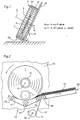
- Figures 1 and 2 show schematically the method according to the invention, in Figure 1 with a view perpendicular to the axis of a coil positioned on the support surface and in Figure 2 with a view parallel to this axis.
- Figure 1 shows as essential device components: an inclined support surface 10, which has a pitch angle ⁇ , and a support means 20, wherein the support surface 10 and support means 20 are arranged such that they can hold a winding 1 together in a defined position.
- the winding 1 with the winding axis A consists of a winding core (not visible), a winding tape 12 and a scale formation 13 of printed products which is wound onto the winding core with the aid of the winding tape.
- the support means 20 is, for example, essentially the same width as or wider than the wound printed products. Since the winding is denser in the area of the winding tape than in the areas next to the winding tape, such a support means will act primarily on the winding tape. This is beneficial for sensitive products. For cases in which the support means 20 is to act more on the printed products, a pair of support means can be provided to the left and right of the winding tape 12 (see, for example, FIG. 3).
- FIG. 2 shows the same device as FIG. 1, but with a viewing angle essentially parallel to the winding axis A. From this, the winding core 11 is visible at the start of the unwinding and in dash-dotted lines (position 11 ') at the end of the winding process.
- the support means 20 can be seen in more detail in this figure. It consists, for example, of a support belt 21 which runs over at least three guide rollers 22/23/24 and is longer than the shortest connection between the rollers. As a result, the belt 21 between the rollers 22 and 23, where it is loaded by the winding 1, is pressed downward in an area that at least partially abuts the winding circumference.
- the device has a conveying means, for example a conveying belt 30, on which the developed scale stream 31 is conveyed away.
- the conveyor belt 30 runs over a guide roller 26 which is arranged in the region of the periphery of the roll 1.
- the device according to FIG. 2 also has a means for rolling up the winding tape 12, for example a tape roll 41 arranged on a drive shaft 40.
- a means for rolling up the winding tape 12 for example a tape roll 41 arranged on a drive shaft 40.
- the unwinding process proceeds as follows: the roll 1 is placed on the inclined support surface 10 in such a way that it is supported by the support means 20.
- the tape end of the winding tape 12 is detached from the roll 1 and pulled by the roll so far from the roll that it can be guided away via the guide roller 23 and attached to the tape roll 41.
- at least the belt roll 41 and the conveyor belt 30 are driven at the same peripheral speed, as a result of which the winding 1 is rotated, the winding belt 12 is rolled up on the belt roll 41 and the unwanted scale stream 31 is conveyed away on the conveyor belt 30.
- the support belt 21 can also be driven during the winding process or it can be arranged to be freely movable such that it is driven by the movement of the products to be unwound or of the winding belt 12.
- a support means must be provided that moves with the unwinding movement in such a way that a sliding movement of the support means 20 relative to the moving parts of the roll 1 is avoided as much as possible, since this can lead to a build-up of winding tape and / or wound printed products on Entrance into the support area, which can lead to destabilization of the winding and / or damage to the product.
- support means 20 shown in FIG. 2 in the form of a support belt 21
- other support means are also conceivable, for example two V-shaped belts or a row of support rollers.
- the force relationships in the method according to the invention can be seen from FIG.
- the winding has a weight P which can be divided into a normal component N perpendicular to the support surface 10 and a parallel component F parallel to the support surface.
- the frictional force R to be overcome when the winding moves on the support surface is equal to ⁇ ⁇ N or ⁇ ⁇ P ⁇ sin ⁇ , where ⁇ is the coefficient of friction between the end face of the winding and the support surface.
- This frictional force acts as braking, in particular when the reel rotates during unwinding, by means of which the tape tension is maintained in the reel.
- the winding on the bearing surface 10 is driven downwards by the slope-driving force H, which corresponds to the difference between the parallel component F and the friction force R.
- the pressure that the winding exerts on the proppant during unwinding is greater or smaller. At standstill, this pressure corresponds to the maximum of the parallel component F of the winding weight P.
- the friction between the end face of the winding and the support surface can be set by appropriate selection of the surface of the support surface ( ⁇ ) and by corresponding selection of ⁇ in such a way that sufficient tape tension can be maintained even with a small winding weight.
- the configuration of the support means 20 is to be matched to the parallel component F.
- the power of the shaft 40 is to be matched to the friction at maximum weight.
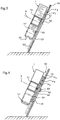
- Figures 3 to 5 show devices with such additional elements. All these figures are sections through the unwinding device and a roll 1 positioned thereon, the roll axis A lying in the cutting plane.
- FIG. 3 shows an embodiment with an additional element in the form of an end plate 50.
- This end plate 50 has a pin 51, which extends into the inner cavity of the winding core 11 and on which a freely rotating roller can be provided.
- the end plate 50 has a guide element 52 facing away from the winding 1, which is guided in a guide slot 53 in the support surface 10, such that the end plate 50 can be moved up and down on the support surface 10, but cannot be rotated.
- the two surfaces of the plate 50 and the surface of the support surface 10 are matched to one another in such a way that a friction coefficient ⁇ 1 is produced between the winding end face and the surface of the end plate 50 facing the winding, and in such a way that between the surface of the end plate 50 facing away from the winding and the Contact surface 10 creates a coefficient of friction ⁇ 2 , where ⁇ 1 generates an optimal braking force for the rotation of the winding, ⁇ 2 an optimal braking force for the slipping of the winding. It turns out that it is advantageous to choose ⁇ 1 smaller than ⁇ 2 .
- the end plate 50 is operatively connected to a drive for a rotation, it is possible not only to unwind coils with the same device but also to wind a scale formation on a winding core or to wind at least a part of the scale formation that has just been unwound back onto the winding. So that the pressure between the underside of the winding and the support means 20 does not become too great in such a case, it may be necessary to drive not only the rotational movement of the winding but also its upward sliding movement accordingly.
- FIG. 4 shows a further additional element in the form of a double end plate 60 positioned between the winding 1 and the support surface 10.
- the double end plate 60 consists of a rotating plate 61 directed against the winding 1 and a sliding plate 62 directed against the supporting surface 10, the rotating plate, for example, by means of pins 63 is rotatably attached to the slide plate.
- the double end plate 60 can be moved up and down on the support surface 10, for example by means of a guide element 52 and a guide slot 53, but is secured against rotation.
- the surfaces of the rotating plate 61, the sliding plate 62 and the support surface 10 are designed in such a way that the coefficient of friction ⁇ 3 between the end face of the winding and the rotating plate 61 is large, so that the winding and the rotating plate rotate together, and the coefficient of friction ⁇ 4 between the rotating plate 61 and the sliding plate 62 has an appropriate braking force for the winding rotation and that the coefficient of friction ⁇ 5 between the slide plate 62 and the support surface 10 gives an adequate braking force for the downward slide movement.
- a winding device is advantageous for sensitive printed products, in particular for products which are no longer trimmed in the region of the edges forming the end faces in the winding.
- FIG. 5 shows a further variant of an unwinding device with an additional element, which in this case consists of a spindle 70 and an axis element 71 which can be moved up and down on the spindle 70.
- the spindle 70 is arranged parallel to the support surface 10 and on its side facing away from the winding 1 and is freely rotatable.
- the axis element 71 protrudes through a corresponding slot 72 in the support surface 10 and extends slightly into the inner cavity of the winding core 11 of a winding 1 positioned on the support surface 10.
- the thread of the spindle 70 and the axis element 71 is designed such that the arrangement is not self-locking and that the weight of the, so to speak, empty winding core is still sufficient to rotate the spindle 70 and thus to move the axle element 71 with the winding 1 hanging thereon downward.
- Spindle 70 and axle element 71 not only absorb part of the slope-driving force, but also the winding is laterally stabilized, which allows a simpler configuration of the support means 20.
- that part of the axle element 71 which projects into the winding core 11 can have a freely rotating roller which rolls during winding in the winding core.
- Spindle 70 and axle element 71 can also be designed as a system with self-locking and the spindle 70 can be driven. The winding then moves downward at a speed corresponding to the spindle drive speed, the entire slope-driving force of the axis element 71 and spindle 70 being able to be absorbed. In such a case, the support means 20 may be missing.
- a drivable spindle 70 can also be used for a device with which not only is to be unwound but also to be wound up.
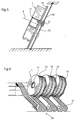
- FIG. 6 shows a group of unwinding devices with which adjacent feed points of a processing line are equipped to illustrate the space savings which can be achieved by the method according to the invention and by the device according to the invention.
- the tape rolls are not shown.
- the unwinding devices are loaded with windings from the side facing the viewer or from above.
- a further variant of the device according to the invention consists in covering a surface of a pair of surfaces rubbing against one another, in particular the surface of the end plate or support surface rubbing on the winding end face by means of a multiplicity of small, braked rollers (roller axes parallel to Radii) or to be replaced by a star-shaped arrangement of braked tapered rollers or to be partially replaced by individual rollers or tapered rollers.
- a multiplicity of small, braked rollers roller axes parallel to Radii
- a star-shaped arrangement of braked tapered rollers or to be partially replaced by individual rollers or tapered rollers.
- an embodiment with a star-shaped arrangement of tapered rollers would be suitable as a device for both unwinding and rewinding if the tapered rollers can be operatively connected to a corresponding drive.
- a further variant of the method according to the invention is that the winding core is held in a stationary position during the unwinding with corresponding holding means.
- the conveying means 30 and the support means 20 it would be necessary for the conveying means 30 and the support means 20 to follow the winding diameter which is reduced as it is unwound. Since, in such a case, the holding means can absorb the entire slope-driving force, the supporting means 20 must be equipped accordingly or may be missing entirely.
Landscapes
- Engineering & Computer Science (AREA)
- Mechanical Engineering (AREA)
- Replacement Of Web Rolls (AREA)
- Unwinding Webs (AREA)
Applications Claiming Priority (3)
| Application Number | Priority Date | Filing Date | Title |
|---|---|---|---|
| CH41496 | 1996-02-16 | ||
| CH414/96 | 1996-02-16 | ||
| CH41496 | 1996-02-16 |
Publications (2)
| Publication Number | Publication Date |
|---|---|
| EP0790204A1 true EP0790204A1 (fr) | 1997-08-20 |
| EP0790204B1 EP0790204B1 (fr) | 2002-05-02 |
Family
ID=4186492
Family Applications (1)
| Application Number | Title | Priority Date | Filing Date |
|---|---|---|---|
| EP97100853A Expired - Lifetime EP0790204B1 (fr) | 1996-02-16 | 1997-01-21 | Méthode et dispositif pour dérouler des produits imprimés en formation imbriquée |
Country Status (5)
| Country | Link |
|---|---|
| US (1) | US5772148A (fr) |
| EP (1) | EP0790204B1 (fr) |
| CA (1) | CA2195590A1 (fr) |
| DE (1) | DE59707126D1 (fr) |
| DK (1) | DK0790204T3 (fr) |
Citations (8)
| Publication number | Priority date | Publication date | Assignee | Title |
|---|---|---|---|---|
| US1883222A (en) * | 1931-01-12 | 1932-10-18 | Wood Newspaper Mach Corp | Paper roll braking device |
| FR1306131A (fr) * | 1961-09-01 | 1962-10-13 | British Insulated Callenders | Appareil perfectionné destiné à contrôler la tension appliquée à des rubans |
| GB2107681A (en) * | 1981-10-12 | 1983-05-05 | Ferag Ag | Apparatus for the storage of flat products arriving in an imbricated formation especially printed products |
| US4637198A (en) * | 1985-07-01 | 1987-01-20 | Ferag Ag | Method and apparatus for temporarily storing printed products arriving in an imbricated formation |
| EP0232553A1 (fr) * | 1986-01-27 | 1987-08-19 | Ferag AG | Dispositif pour enrouler des objets plats arrivant en formation continue imbriqué |
| EP0447498A1 (fr) | 1989-10-03 | 1991-09-25 | Bell Helicopter Textron Inc. | Assemblage coulissant autoreglable pour interrupteur indiquant la masse exercee sur le train d'atterrissage |
| EP0447903A1 (fr) | 1990-03-23 | 1991-09-25 | Ferag AG | Dispositif pour dérouler des produits plats flexibles d'une bobine |
| US5174518A (en) * | 1990-12-10 | 1992-12-29 | Kanzaki Paper Manufacturing Co., Ltd. | Paper feeding device and an application thereof |
Family Cites Families (6)
| Publication number | Priority date | Publication date | Assignee | Title |
|---|---|---|---|---|
| US2928618A (en) * | 1957-04-26 | 1960-03-15 | Peer A Locke | Paper holder |
| DE1893781U (de) * | 1962-11-26 | 1964-05-27 | Hauni Werke Koerber & Co Kg | Zufuehrungsvorrichtung in zigarettenmaschinen oder in anderen maschinen, die eine aus einem aufgewickelten streifen bestehende bobine verarbeiten. |
| US3334838A (en) * | 1964-09-05 | 1967-08-08 | Kopp & Odenwald | Apparatus for feeding wound material to a processing machine |
| US4336911A (en) * | 1980-09-22 | 1982-06-29 | Fairchild Wayne K | Frictional tensioning device |
| JP2525640B2 (ja) * | 1987-05-27 | 1996-08-21 | フェラーク アーゲー | 巻取テ―プと一緒にずれ重なり編成で巻心に巻き取られた印刷物を繰出す装置 |
| DE59306228D1 (de) * | 1992-03-19 | 1997-05-28 | Ferag Ag | Verfahren und Vorrichtung zum Auf- und Abwinkeln von Druckprodukten in Schuppenformation |
-
1997
- 1997-01-21 EP EP97100853A patent/EP0790204B1/fr not_active Expired - Lifetime
- 1997-01-21 DE DE59707126T patent/DE59707126D1/de not_active Expired - Fee Related
- 1997-01-21 DK DK97100853T patent/DK0790204T3/da active
- 1997-01-21 CA CA002195590A patent/CA2195590A1/fr not_active Abandoned
- 1997-02-14 US US08/800,757 patent/US5772148A/en not_active Expired - Fee Related
Patent Citations (9)
| Publication number | Priority date | Publication date | Assignee | Title |
|---|---|---|---|---|
| US1883222A (en) * | 1931-01-12 | 1932-10-18 | Wood Newspaper Mach Corp | Paper roll braking device |
| FR1306131A (fr) * | 1961-09-01 | 1962-10-13 | British Insulated Callenders | Appareil perfectionné destiné à contrôler la tension appliquée à des rubans |
| GB2107681A (en) * | 1981-10-12 | 1983-05-05 | Ferag Ag | Apparatus for the storage of flat products arriving in an imbricated formation especially printed products |
| US4637198A (en) * | 1985-07-01 | 1987-01-20 | Ferag Ag | Method and apparatus for temporarily storing printed products arriving in an imbricated formation |
| EP0232553A1 (fr) * | 1986-01-27 | 1987-08-19 | Ferag AG | Dispositif pour enrouler des objets plats arrivant en formation continue imbriqué |
| EP0447498A1 (fr) | 1989-10-03 | 1991-09-25 | Bell Helicopter Textron Inc. | Assemblage coulissant autoreglable pour interrupteur indiquant la masse exercee sur le train d'atterrissage |
| EP0447903A1 (fr) | 1990-03-23 | 1991-09-25 | Ferag AG | Dispositif pour dérouler des produits plats flexibles d'une bobine |
| US5158242A (en) * | 1990-03-23 | 1992-10-27 | Ferag, Ag | Apparatus for the unwinding of flexible sheet-like structures from a roll |
| US5174518A (en) * | 1990-12-10 | 1992-12-29 | Kanzaki Paper Manufacturing Co., Ltd. | Paper feeding device and an application thereof |
Also Published As
| Publication number | Publication date |
|---|---|
| CA2195590A1 (fr) | 1997-08-17 |
| EP0790204B1 (fr) | 2002-05-02 |
| DE59707126D1 (de) | 2002-06-06 |
| DK0790204T3 (da) | 2002-08-19 |
| US5772148A (en) | 1998-06-30 |
Similar Documents
| Publication | Publication Date | Title |
|---|---|---|
| DE69421528T2 (de) | Umwickler mit Kontaktantrieb und Verfahren zur Minimalisierung des Schlupfes zwischen Antriebsrolle und Bahn | |
| DE3123888C2 (de) | Vorrichtung zum Zwischenspeichern von in Schuppenformation anfallenden Zeitungen, Zeitschriften oder dergleichen | |
| DE69308763T2 (de) | Trägerbandloser Etikettenspender und Verfahren zum Spenden | |
| EP0968919B1 (fr) | Procédé et dispositif d'enveloppement d'objets quadrangulaires avec un matériau d'emballage sous forme de bande | |
| EP0792829A2 (fr) | Procédé et dispositif pour enrouler une bande de papier en un rouleau | |
| DE2600522C2 (fr) | ||
| DE3421915A1 (de) | Verfahren und vorrichtung zum aufbauen und handhaben von stapeln aus bahnmaterial | |
| DE69108681T2 (de) | Vorrichtung zum zuführen von Sicherungsbändern. | |
| DE3030798A1 (de) | Verfahren und vorrichtung zum laengsschneiden und aufwickeln von bahnfoermigem material | |
| DE69623409T2 (de) | Schneidvorrichtung zum Schneiden von endlosen Materialbahnen | |
| DE4100210C2 (de) | Verfahren zum Herstellen eines Transformatorwickels | |
| EP0352564B1 (fr) | Procédé et dispositif de manipulation et de traitement ultérieur d'une bande du type en nid d'abeilles | |
| DE69900525T2 (de) | Vorrichtung und Verfahren zum Entfernen des Verpackungsmaterials von einer Materialbahnrolle | |
| AT395956B (de) | Vorrichtung zum zwischenspeichern von in schuppenformation anfallenden druckprodukten | |
| EP1108669A2 (fr) | Dispositif d'enroulage de bobines, en particulier pour une refendeuse | |
| DE2439212B2 (de) | Verfahren und Vorrichtung zum Steuern der Wickelgüte beim Wickeln von bahnförmigem Material | |
| EP0652176B1 (fr) | Dispositif d'enroulage pour les structures flexibles et planes ainsi que la méthode d'enroulement des structures flexibles et planes | |
| DE69107518T2 (de) | Verfahren zur Herstellung eines Transformatorkerns. | |
| DE3040189A1 (de) | Warenbahn-wickelvorrichtung | |
| EP0790204B1 (fr) | Méthode et dispositif pour dérouler des produits imprimés en formation imbriquée | |
| EP0384147B1 (fr) | Procédé et appareil pour l'emmagasinage intermédiaire de produits d'imprimerie pliés, à plusieurs feuilles, comme journaux, magazines et parties de ceux-ci | |
| DE69304481T2 (de) | Vorrichtung zum Herstellen eines Transformarotkernes mit amorphen Stahlbänden die auf dem Kernfenster gewickelt sind | |
| DE2111160B2 (de) | Vorrichtung zum foerdern von metallisierten baendern in einer folienmaterial bearbeitenden plattenpresse | |
| DD254725A5 (de) | Verfahren und vorrichtung von in schuppenformation anfallenden druckereierzeugnissen | |
| DE60118964T2 (de) | Vorrichtung und verfahren zum wickeln von bahnen |
Legal Events
| Date | Code | Title | Description |
|---|---|---|---|
| PUAI | Public reference made under article 153(3) epc to a published international application that has entered the european phase |
Free format text: ORIGINAL CODE: 0009012 |
|
| AK | Designated contracting states |
Kind code of ref document: A1 Designated state(s): CH DE DK GB LI NL |
|
| 17P | Request for examination filed |
Effective date: 19980209 |
|
| 17Q | First examination report despatched |
Effective date: 19991126 |
|
| RTI1 | Title (correction) |
Free format text: METHOD AND DEVICE FOR UNWINDING PRINTED PRODUCTS IN IMBRICATED FORMATION |
|
| GRAG | Despatch of communication of intention to grant |
Free format text: ORIGINAL CODE: EPIDOS AGRA |
|
| GRAG | Despatch of communication of intention to grant |
Free format text: ORIGINAL CODE: EPIDOS AGRA |
|
| GRAH | Despatch of communication of intention to grant a patent |
Free format text: ORIGINAL CODE: EPIDOS IGRA |
|
| GRAH | Despatch of communication of intention to grant a patent |
Free format text: ORIGINAL CODE: EPIDOS IGRA |
|
| REG | Reference to a national code |
Ref country code: GB Ref legal event code: IF02 |
|
| GRAA | (expected) grant |
Free format text: ORIGINAL CODE: 0009210 |
|
| AK | Designated contracting states |
Kind code of ref document: B1 Designated state(s): CH DE DK GB LI NL |
|
| REG | Reference to a national code |
Ref country code: GB Ref legal event code: FG4D Free format text: NOT ENGLISH |
|
| REG | Reference to a national code |
Ref country code: CH Ref legal event code: EP |
|
| GBT | Gb: translation of ep patent filed (gb section 77(6)(a)/1977) |
Effective date: 20020502 |
|
| REF | Corresponds to: |
Ref document number: 59707126 Country of ref document: DE Date of ref document: 20020606 |
|
| REG | Reference to a national code |
Ref country code: CH Ref legal event code: NV Representative=s name: FREI PATENTANWALTSBUERO |
|
| REG | Reference to a national code |
Ref country code: DK Ref legal event code: T3 |
|
| PGFP | Annual fee paid to national office [announced via postgrant information from national office to epo] |
Ref country code: NL Payment date: 20021227 Year of fee payment: 7 |
|
| PLBE | No opposition filed within time limit |
Free format text: ORIGINAL CODE: 0009261 |
|
| STAA | Information on the status of an ep patent application or granted ep patent |
Free format text: STATUS: NO OPPOSITION FILED WITHIN TIME LIMIT |
|
| 26N | No opposition filed |
Effective date: 20030204 |
|
| PGFP | Annual fee paid to national office [announced via postgrant information from national office to epo] |
Ref country code: CH Payment date: 20031209 Year of fee payment: 8 |
|
| PGFP | Annual fee paid to national office [announced via postgrant information from national office to epo] |
Ref country code: GB Payment date: 20040105 Year of fee payment: 8 |
|
| PGFP | Annual fee paid to national office [announced via postgrant information from national office to epo] |
Ref country code: DK Payment date: 20040106 Year of fee payment: 8 |
|
| PGFP | Annual fee paid to national office [announced via postgrant information from national office to epo] |
Ref country code: DE Payment date: 20040108 Year of fee payment: 8 |
|
| PG25 | Lapsed in a contracting state [announced via postgrant information from national office to epo] |
Ref country code: NL Free format text: LAPSE BECAUSE OF NON-PAYMENT OF DUE FEES Effective date: 20040801 |
|
| NLV4 | Nl: lapsed or anulled due to non-payment of the annual fee |
Effective date: 20040801 |
|
| PG25 | Lapsed in a contracting state [announced via postgrant information from national office to epo] |
Ref country code: GB Free format text: LAPSE BECAUSE OF NON-PAYMENT OF DUE FEES Effective date: 20050121 |
|
| PG25 | Lapsed in a contracting state [announced via postgrant information from national office to epo] |
Ref country code: LI Free format text: LAPSE BECAUSE OF NON-PAYMENT OF DUE FEES Effective date: 20050131 Ref country code: DK Free format text: LAPSE BECAUSE OF NON-PAYMENT OF DUE FEES Effective date: 20050131 Ref country code: CH Free format text: LAPSE BECAUSE OF NON-PAYMENT OF DUE FEES Effective date: 20050131 |
|
| REG | Reference to a national code |
Ref country code: CH Ref legal event code: PFA Owner name: FERAG AG Free format text: FERAG AG#ZUERICHSTRASSE 74#8340 HINWIL (CH) -TRANSFER TO- FERAG AG#PATENTABTEILUNG Z. H. MARKUS FELIX ZUERICHSTRASSE 74#8340 HINWIL (CH) |
|
| PG25 | Lapsed in a contracting state [announced via postgrant information from national office to epo] |
Ref country code: DE Free format text: LAPSE BECAUSE OF NON-PAYMENT OF DUE FEES Effective date: 20050802 |
|
| REG | Reference to a national code |
Ref country code: DK Ref legal event code: EBP |
|
| GBPC | Gb: european patent ceased through non-payment of renewal fee |
Effective date: 20050121 |
|
| REG | Reference to a national code |
Ref country code: CH Ref legal event code: PL |