EP0790365A1 - Profilé raccord pour panneaux de revêtement - Google Patents
Profilé raccord pour panneaux de revêtement Download PDFInfo
- Publication number
- EP0790365A1 EP0790365A1 EP97100209A EP97100209A EP0790365A1 EP 0790365 A1 EP0790365 A1 EP 0790365A1 EP 97100209 A EP97100209 A EP 97100209A EP 97100209 A EP97100209 A EP 97100209A EP 0790365 A1 EP0790365 A1 EP 0790365A1
- Authority
- EP
- European Patent Office
- Prior art keywords
- legs
- profile
- pair
- connecting rail
- ceiling
- Prior art date
- Legal status (The legal status is an assumption and is not a legal conclusion. Google has not performed a legal analysis and makes no representation as to the accuracy of the status listed.)
- Granted
Links
- 238000005253 cladding Methods 0.000 title claims abstract description 21
- 239000003000 extruded plastic Substances 0.000 claims abstract description 3
- 238000002347 injection Methods 0.000 claims description 2
- 239000007924 injection Substances 0.000 claims description 2
- 239000004033 plastic Substances 0.000 claims description 2
- 229920003023 plastic Polymers 0.000 claims description 2
- 230000004308 accommodation Effects 0.000 abstract 2
- 230000000694 effects Effects 0.000 description 4
- 230000006835 compression Effects 0.000 description 2
- 238000007906 compression Methods 0.000 description 2
- 239000006260 foam Substances 0.000 description 2
- 239000011810 insulating material Substances 0.000 description 2
- 238000004519 manufacturing process Methods 0.000 description 2
- -1 polyethylene Polymers 0.000 description 2
- 239000004698 Polyethylene Substances 0.000 description 1
- 239000004743 Polypropylene Substances 0.000 description 1
- 241000283984 Rodentia Species 0.000 description 1
- 239000011093 chipboard Substances 0.000 description 1
- 238000010276 construction Methods 0.000 description 1
- 238000005520 cutting process Methods 0.000 description 1
- 238000001125 extrusion Methods 0.000 description 1
- 238000003780 insertion Methods 0.000 description 1
- 230000037431 insertion Effects 0.000 description 1
- 238000009434 installation Methods 0.000 description 1
- 239000000463 material Substances 0.000 description 1
- 238000000034 method Methods 0.000 description 1
- 239000002991 molded plastic Substances 0.000 description 1
- 230000002093 peripheral effect Effects 0.000 description 1
- 229920000573 polyethylene Polymers 0.000 description 1
- 229920001155 polypropylene Polymers 0.000 description 1
- 238000003860 storage Methods 0.000 description 1
- 239000002023 wood Substances 0.000 description 1
Images
Classifications
-
- E—FIXED CONSTRUCTIONS
- E04—BUILDING
- E04B—GENERAL BUILDING CONSTRUCTIONS; WALLS, e.g. PARTITIONS; ROOFS; FLOORS; CEILINGS; INSULATION OR OTHER PROTECTION OF BUILDINGS
- E04B9/00—Ceilings; Construction of ceilings, e.g. false ceilings; Ceiling construction with regard to insulation
- E04B9/06—Ceilings; Construction of ceilings, e.g. false ceilings; Ceiling construction with regard to insulation characterised by constructional features of the supporting construction, e.g. cross section or material of framework members
- E04B9/065—Ceilings; Construction of ceilings, e.g. false ceilings; Ceiling construction with regard to insulation characterised by constructional features of the supporting construction, e.g. cross section or material of framework members comprising supporting beams having a folded cross-section
-
- E—FIXED CONSTRUCTIONS
- E04—BUILDING
- E04B—GENERAL BUILDING CONSTRUCTIONS; WALLS, e.g. PARTITIONS; ROOFS; FLOORS; CEILINGS; INSULATION OR OTHER PROTECTION OF BUILDINGS
- E04B9/00—Ceilings; Construction of ceilings, e.g. false ceilings; Ceiling construction with regard to insulation
- E04B9/18—Means for suspending the supporting construction
-
- E—FIXED CONSTRUCTIONS
- E04—BUILDING
- E04B—GENERAL BUILDING CONSTRUCTIONS; WALLS, e.g. PARTITIONS; ROOFS; FLOORS; CEILINGS; INSULATION OR OTHER PROTECTION OF BUILDINGS
- E04B9/00—Ceilings; Construction of ceilings, e.g. false ceilings; Ceiling construction with regard to insulation
- E04B9/22—Connection of slabs, panels, sheets or the like to the supporting construction
- E04B9/24—Connection of slabs, panels, sheets or the like to the supporting construction with the slabs, panels, sheets or the like positioned on the upperside of, or held against the underside of the horizontal flanges of the supporting construction or accessory means connected thereto
- E04B9/241—Connection of slabs, panels, sheets or the like to the supporting construction with the slabs, panels, sheets or the like positioned on the upperside of, or held against the underside of the horizontal flanges of the supporting construction or accessory means connected thereto with the slabs, panels, sheets or the like positioned on the upperside of the horizontal flanges of the supporting construction
- E04B9/242—Connection of slabs, panels, sheets or the like to the supporting construction with the slabs, panels, sheets or the like positioned on the upperside of, or held against the underside of the horizontal flanges of the supporting construction or accessory means connected thereto with the slabs, panels, sheets or the like positioned on the upperside of the horizontal flanges of the supporting construction with separate retaining elements
-
- E—FIXED CONSTRUCTIONS
- E04—BUILDING
- E04F—FINISHING WORK ON BUILDINGS, e.g. STAIRS, FLOORS
- E04F13/00—Coverings or linings, e.g. for walls or ceilings
- E04F13/07—Coverings or linings, e.g. for walls or ceilings composed of covering or lining elements; Sub-structures therefor; Fastening means therefor
- E04F13/08—Coverings or linings, e.g. for walls or ceilings composed of covering or lining elements; Sub-structures therefor; Fastening means therefor composed of a plurality of similar covering or lining elements
- E04F13/0801—Separate fastening elements
- E04F13/0803—Separate fastening elements with load-supporting elongated furring elements between wall and covering elements
- E04F13/081—Separate fastening elements with load-supporting elongated furring elements between wall and covering elements with additional fastening elements between furring elements and covering elements
- E04F13/0812—Separate fastening elements with load-supporting elongated furring elements between wall and covering elements with additional fastening elements between furring elements and covering elements fixed by means of spring action
-
- E—FIXED CONSTRUCTIONS
- E04—BUILDING
- E04F—FINISHING WORK ON BUILDINGS, e.g. STAIRS, FLOORS
- E04F19/00—Other details of constructional parts for finishing work on buildings
- E04F19/02—Borders; Finishing strips, e.g. beadings; Light coves
- E04F19/06—Borders; Finishing strips, e.g. beadings; Light coves specially designed for securing panels or masking the edges of wall- or floor-covering elements
Definitions
- the invention relates to a connecting rail in I-profile shape for cladding panels to be mounted in the wall or ceiling area of buildings, having a first pair of profile legs and a second pair of profile legs lying essentially parallel to the same, and a central web extending perpendicularly between them, the opposite sides of the profile legs Leg pairs each have a receiving space for an edge region of a cladding panel is formed.
- Such cladding panels are e.g. Insulating or insulating boards made of hard foam or the like. Insulating material or wood, veneer or chipboard.
- the respective receiving space between the legs of the I-profile is dimensioned in accordance with the thickness of the cladding panel. This means that for each thickness of the cladding panels to be processed, connecting rails dimensioned with their receiving space must be available. This results in an increased manufacturing outlay for the connecting rails, connected with a corresponding expenditure in the magazine or storage.
- the invention has for its object to provide a connecting rail of the type specified, which is suitable to accommodate cladding panels of different thickness for their connection within their design limits.
- the profile legs of the first pair of legs are each provided on their outer edge with a spring bar directed towards the opposite profile leg of the second pair of legs, reducing the receiving space but resiliently flexible towards the profile leg of the first pair of legs.
- cladding panels of different thicknesses can be accommodated in the respective receiving space of the connecting rail in that when the edge region of the cladding panel is inserted into the receiving space, the respective female connector is pressed more or less towards the profile leg of the first pair of legs against elastic resistance, depending on the thickness of the panel.
- the resilient forces inherent in the resilient female connector simultaneously cause the cladding panel inserted into the edge of the receiving space to be pressed against the profile leg of the second pair of legs and to be held in the receiving space by a clamping effect.
- cladding panels with different thicknesses in particular insulating panels, can be securely fixed within the design limits of the connecting rail in its respective receiving space.
- the spring strips supported with spring pressure on the surface of the cladding panel with their edges facing the second pair of legs also offer desirable protection of the cladding panels in their cutting areas compared to small rodents.
- the connecting rail is advantageously formed by an extruded plastic profile body, preferably made of PVC, on which the female connectors are integrally formed.
- PVC polyvinyl styrene
- the connecting rail is advantageously formed by an extruded plastic profile body, preferably made of PVC, on which the female connectors are integrally formed.
- connection rail can be fastened to the wall or ceiling of the space to be provided with the cladding panels in a simple manner by means of the profile legs of the first pair of legs facing the wall or ceiling in the installed position of the rail, by means of which nails or preferably screws into suitable parts of the wall - or ceiling construction, such as wooden ceiling beams or slats.
- a head strip is integrally formed on the top of the first pair of legs, by means of which it can be brought into a latching or similar holding engagement with a receiving groove in a wall or ceiling-mounted holder. This enables a quick assembly of the connecting rail.
- the invention also includes a kit for mounting cladding panels consisting of a connecting rail of the type specified with top header and a number of individual, wall or ceiling mounted brackets with an open to the connecting rail receiving groove for a snap or the like at specified intervals with the header of the connecting rail.
- brackets can advantageously each be formed by a two-legged profile piece, one leg of the ceiling-side attachment, e.g. by means of nails or screws on a wooden beam, and whose other leg has the receiving groove.
- the profile pieces are expediently formed from injection molded plastic parts, with polyethylene and polypropylene in particular being considered as the material.
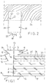
- cladding or ceiling panel 9 for example made of hard foam.
- a female connector 11 is integrally formed, which is directed towards the lower profile leg 5 and 6 and thereby initially reduces the receiving space 7 from above.
- the female connector 11 is pushed up toward the upper profile leg 3 or 4 against elastic resistance, so that the peripheral region 8 is clamped between the lower end of the female connector 11 and the lower profile leg 5 or 6.
- Different thicknesses of the ceiling plate 9 are absorbed within the design limits of the connecting rail 1 by more or less strong compression of the female connector 11.
- the female connector 11 in the left half of the connecting rail 1, the female connector 11 is in its initial state, i.e. before inserting the edge area 8 of a ceiling panel 9. It can be seen that the female connector 11 has an elastically compressible side fold 12 which is molded toward the central web 2 and which gives the female connector 11 a controlled movement in the direction of the profile legs 3 or 4 under the pressure of the edge region 8 of a ceiling plate 9 inserted into the receiving space 7.
- the side gussets 12 are dimensioned such that in their compressed state, after the insertion of a ceiling plate 9, as shown in the right half of FIG. 1, with their outer folded edges 13 they are located within a vertical envelope plane of the I-profile, between the outer edge 10 of the upper profile leg 3 and the corresponding outer edge 14 of the lower profile leg 5 or the outer edge 10 of the upper profile leg 4 and the corresponding outer edge 14 of the lower profile leg 6 runs.
- the spring strips 11 do not protrude beyond the width of the I-profile. This provides the guarantee that a next adjacent, similar to the illustrated connecting rail 1 extending, further connecting rail can connect to the illustrated connecting rail 1.
- the free end of the female connector 11 is formed by an obliquely to the central web 2 downward facing plate support web 15 against which the ceiling panel 9 is pushed with its edge area 8 when inserted in order to further slide in the female connector 11 by executing a folding movement around the outer Compress the folded edge 13 and the inner folded edge 16 and the outer edge 10 of the upper profile leg 3 or 4.
- the side fold 12 is thereby reduced accordingly.
- the ceiling plate 9 is securely held between the lower edge of the plate contact web 15 and the lower profile leg 5 or 6 by clamping action, this clamping effect can be increased further by initially lowering the lower profile leg 5, 6 in the direction of the upper profile leg 3 , 4 are elastically biased.
- a locking head strip 17 is integrally formed, by means of which it can be locked with a locking groove 18 of brackets 19 mounted on the ceiling.
- the brackets 19 are each formed by an angular profile piece, one vertical leg 20 of which is used for fastening on the ceiling and the other, horizontal leg 21 of which has the locking groove 18 provided by a groove strip 22.
- FIG. 2 shows the holder in its state fastened to a ceiling beam 23 with the aid of screws or nails 24.
- the brackets 19 fastened to the ceiling beams 23 or corresponding slats of a lattice attached to the ceiling come into locking engagement at intervals corresponding to the beam or slat spacing with the locking head strip 17 running over the length of the connecting rail 1 when the connecting rail 1 has the locking head profile from below its locking head strip 17 is pressed into the correspondingly shaped groove.
- the maximum compression of the female connector 11 is shown, in which a ceiling panel 9 of 60 mm, for example, rests with its surface 25 on the lower edge of the female connector 11.
- the dash-dotted lines 26 indicate that even less thick ceiling panels 9, for example with a thickness of 50 mm or less, can be included with a clamping effect between the female connector 11 and the profile leg 6, up to the lower limit line 27, which is approximately in The height of the lower edge of the female connector 11 runs in its initial state and thus marks the lower limit for a ceiling plate 9 to be sandwiched between the female connector 11 and the profile leg 5 or 6 with only a minimal clamping effect.
Landscapes
- Engineering & Computer Science (AREA)
- Architecture (AREA)
- Civil Engineering (AREA)
- Structural Engineering (AREA)
- Physics & Mathematics (AREA)
- Electromagnetism (AREA)
- Building Environments (AREA)
- Joining Of Building Structures In Genera (AREA)
- Installation Of Indoor Wiring (AREA)
- Mutual Connection Of Rods And Tubes (AREA)
- Bathtub Accessories (AREA)
- Insulating Bodies (AREA)
- Details Of Indoor Wiring (AREA)
Applications Claiming Priority (2)
| Application Number | Priority Date | Filing Date | Title |
|---|---|---|---|
| DE29602772U | 1996-02-16 | ||
| DE29602772U DE29602772U1 (de) | 1996-02-16 | 1996-02-16 | Verbindungsschiene für Verkleidungsplatten |
Publications (2)
| Publication Number | Publication Date |
|---|---|
| EP0790365A1 true EP0790365A1 (fr) | 1997-08-20 |
| EP0790365B1 EP0790365B1 (fr) | 2001-08-29 |
Family
ID=8019603
Family Applications (1)
| Application Number | Title | Priority Date | Filing Date |
|---|---|---|---|
| EP97100209A Expired - Lifetime EP0790365B1 (fr) | 1996-02-16 | 1997-01-09 | Profilé raccord pour panneaux de revêtement |
Country Status (6)
| Country | Link |
|---|---|
| EP (1) | EP0790365B1 (fr) |
| AT (1) | ATE204940T1 (fr) |
| DE (2) | DE29602772U1 (fr) |
| DK (1) | DK0790365T3 (fr) |
| ES (1) | ES2162135T3 (fr) |
| PT (1) | PT790365E (fr) |
Families Citing this family (1)
| Publication number | Priority date | Publication date | Assignee | Title |
|---|---|---|---|---|
| AT509506B1 (de) | 2010-02-25 | 2012-01-15 | Lenz Bernhard | Anordnung zur befestigung zumindest einer platte an einer gebäudewand |
Citations (8)
| Publication number | Priority date | Publication date | Assignee | Title |
|---|---|---|---|---|
| GB547483A (en) * | 1941-02-26 | 1942-08-28 | Bert Inkley | Improvements in h-section rails for supporting wall and ceiling lining boards, sheets or slabs |
| BE703526A (fr) * | 1967-09-06 | 1968-02-01 | ||
| GB1353001A (en) * | 1970-01-22 | 1974-05-15 | Bradbury Sa | Interlocking joints for panels |
| GB2120702A (en) * | 1982-05-25 | 1983-12-07 | Hunter Douglas Ind Bv | Clip for wall or ceiling panel structure |
| GB2144464A (en) * | 1983-08-05 | 1985-03-06 | Philip Simms | Fixing of lining boards |
| DE8513369U1 (de) * | 1985-05-07 | 1985-10-10 | Caspari, Hans, 7513 Stutensee | Fugen- und Stoßleiste |
| US4913576A (en) * | 1989-06-16 | 1990-04-03 | Dyrotech Industries, Inc. | Molding bracket for covering the end of a panel subject to thermal expansion |
| US5325647A (en) * | 1992-08-21 | 1994-07-05 | Armstrong World Industries, Inc. | Composite ceiling grid |
Family Cites Families (2)
| Publication number | Priority date | Publication date | Assignee | Title |
|---|---|---|---|---|
| US2005427A (en) * | 1933-09-28 | 1935-06-18 | Julius J Ohlis | Tiling and the like |
| DE9116095U1 (de) * | 1991-12-23 | 1992-02-27 | Metallbau Ralf Boetker GmbH & Co., 2805 Stuhr | Kunststoffprofil für die Fassadenverkleidung von Gebäuden |
-
1996
- 1996-02-16 DE DE29602772U patent/DE29602772U1/de not_active Expired - Lifetime
-
1997
- 1997-01-09 DE DE59704408T patent/DE59704408D1/de not_active Expired - Fee Related
- 1997-01-09 ES ES97100209T patent/ES2162135T3/es not_active Expired - Lifetime
- 1997-01-09 PT PT97100209T patent/PT790365E/pt unknown
- 1997-01-09 DK DK97100209T patent/DK0790365T3/da active
- 1997-01-09 AT AT97100209T patent/ATE204940T1/de not_active IP Right Cessation
- 1997-01-09 EP EP97100209A patent/EP0790365B1/fr not_active Expired - Lifetime
Patent Citations (8)
| Publication number | Priority date | Publication date | Assignee | Title |
|---|---|---|---|---|
| GB547483A (en) * | 1941-02-26 | 1942-08-28 | Bert Inkley | Improvements in h-section rails for supporting wall and ceiling lining boards, sheets or slabs |
| BE703526A (fr) * | 1967-09-06 | 1968-02-01 | ||
| GB1353001A (en) * | 1970-01-22 | 1974-05-15 | Bradbury Sa | Interlocking joints for panels |
| GB2120702A (en) * | 1982-05-25 | 1983-12-07 | Hunter Douglas Ind Bv | Clip for wall or ceiling panel structure |
| GB2144464A (en) * | 1983-08-05 | 1985-03-06 | Philip Simms | Fixing of lining boards |
| DE8513369U1 (de) * | 1985-05-07 | 1985-10-10 | Caspari, Hans, 7513 Stutensee | Fugen- und Stoßleiste |
| US4913576A (en) * | 1989-06-16 | 1990-04-03 | Dyrotech Industries, Inc. | Molding bracket for covering the end of a panel subject to thermal expansion |
| US5325647A (en) * | 1992-08-21 | 1994-07-05 | Armstrong World Industries, Inc. | Composite ceiling grid |
Also Published As
| Publication number | Publication date |
|---|---|
| DE29602772U1 (de) | 1996-04-04 |
| PT790365E (pt) | 2002-02-28 |
| DE59704408D1 (de) | 2001-10-04 |
| ES2162135T3 (es) | 2001-12-16 |
| EP0790365B1 (fr) | 2001-08-29 |
| ATE204940T1 (de) | 2001-09-15 |
| DK0790365T3 (da) | 2001-12-17 |
Similar Documents
| Publication | Publication Date | Title |
|---|---|---|
| DE3688977T2 (de) | System von trennwandplatten. | |
| DE2747611A1 (de) | Einrichtung zum verbinden von tafeln | |
| DE2736079C3 (de) | Trägerschiene für einrastbare Reihenklemmen sowie Reihenklemme hierfür | |
| DE202007016585U1 (de) | Profilschienensystem | |
| WO2003012947A1 (fr) | Structure | |
| DE2435147C3 (de) | Aus teilweise abgebogenen Profilstangen gebildetes Gestell | |
| DE2252535A1 (de) | Befestigungseinrichtung fuer wandverkleidungen | |
| DE9301324U1 (de) | Halter | |
| DE2607240A1 (de) | Wandverkleidung mit befestigungsklammer | |
| DE102013225173B4 (de) | Montageprofilsystem für plattenförmige Module | |
| DE1607667B2 (de) | Gasfilter-haltevorrichtung | |
| DE202010010620U1 (de) | Bodenabdeckung | |
| DE4242589C2 (de) | Anordnung, insbesondere für Schaltschranktür | |
| DE69303136T2 (de) | Blechklammer zum Verbinden von auf Gehrung geschnittenen Profilelementen | |
| EP0790365B1 (fr) | Profilé raccord pour panneaux de revêtement | |
| EP0550882A1 (fr) | Dispositif de fixation pour un revêtement de mur de bâtiment | |
| EP4003096A1 (fr) | Pince de fixation pour fixer un élément de paroi d'un meuble à une structure de meuble et meuble comprenant au moins une pince de fixation | |
| DE9205273U1 (de) | Befestigungselement zur verdeckten Halterung | |
| EP1430579A1 (fr) | Socle pour un coffret de distribution | |
| EP0067970A1 (fr) | Dispositif de fixation pour éléments de façade | |
| EP0033904B1 (fr) | Agrafe métallique pour revêtements de murs et de plafonds | |
| EP0687790B1 (fr) | Raccord rectiligne pour profilés intercalaires creux de vitrages isolants | |
| DE1937443A1 (de) | Wand- und Deckenteile zur Bildung von Raeumen | |
| DE2432604C2 (de) | Verfahren und Vorrichtung zum Befestigen von Lamellen mit profiliertem Querschnitt insbesondere einer Sonnenschutzblende an parallelen Profilträgern | |
| DE9013711U1 (de) | Regalboden mit durch Abkantungen gebildeten Versteifungsprofilen |
Legal Events
| Date | Code | Title | Description |
|---|---|---|---|
| PUAI | Public reference made under article 153(3) epc to a published international application that has entered the european phase |
Free format text: ORIGINAL CODE: 0009012 |
|
| AK | Designated contracting states |
Kind code of ref document: A1 Designated state(s): AT BE CH DE DK ES FI FR GB GR IE IT LI LU NL PT SE |
|
| AX | Request for extension of the european patent |
Free format text: LT PAYMENT 970130;LV PAYMENT 970130;SI PAYMENT 970130 |
|
| 17P | Request for examination filed |
Effective date: 19971105 |
|
| 17Q | First examination report despatched |
Effective date: 19990112 |
|
| GRAG | Despatch of communication of intention to grant |
Free format text: ORIGINAL CODE: EPIDOS AGRA |
|
| GRAG | Despatch of communication of intention to grant |
Free format text: ORIGINAL CODE: EPIDOS AGRA |
|
| GRAH | Despatch of communication of intention to grant a patent |
Free format text: ORIGINAL CODE: EPIDOS IGRA |
|
| GRAH | Despatch of communication of intention to grant a patent |
Free format text: ORIGINAL CODE: EPIDOS IGRA |
|
| GRAA | (expected) grant |
Free format text: ORIGINAL CODE: 0009210 |
|
| AK | Designated contracting states |
Kind code of ref document: B1 Designated state(s): AT BE CH DE DK ES FI FR GB GR IE IT LI LU NL PT SE |
|
| AX | Request for extension of the european patent |
Free format text: LT PAYMENT 19970130;LV PAYMENT 19970130;SI PAYMENT 19970130 |
|
| LTIE | Lt: invalidation of european patent or patent extension | ||
| REF | Corresponds to: |
Ref document number: 204940 Country of ref document: AT Date of ref document: 20010915 Kind code of ref document: T |
|
| REG | Reference to a national code |
Ref country code: CH Ref legal event code: EP |
|
| REG | Reference to a national code |
Ref country code: IE Ref legal event code: FG4D Free format text: GERMAN |
|
| REF | Corresponds to: |
Ref document number: 59704408 Country of ref document: DE Date of ref document: 20011004 |
|
| REG | Reference to a national code |
Ref country code: CH Ref legal event code: NV Representative=s name: PATENTANWAELTE FELDMANN & PARTNER AG |
|
| GBT | Gb: translation of ep patent filed (gb section 77(6)(a)/1977) |
Effective date: 20011117 |
|
| ET | Fr: translation filed | ||
| REG | Reference to a national code |
Ref country code: ES Ref legal event code: FG2A Ref document number: 2162135 Country of ref document: ES Kind code of ref document: T3 |
|
| REG | Reference to a national code |
Ref country code: GB Ref legal event code: IF02 |
|
| REG | Reference to a national code |
Ref country code: PT Ref legal event code: SC4A Free format text: AVAILABILITY OF NATIONAL TRANSLATION Effective date: 20011112 Ref country code: GR Ref legal event code: EP Ref document number: 20010401973 Country of ref document: GR |
|
| PLBE | No opposition filed within time limit |
Free format text: ORIGINAL CODE: 0009261 |
|
| STAA | Information on the status of an ep patent application or granted ep patent |
Free format text: STATUS: NO OPPOSITION FILED WITHIN TIME LIMIT |
|
| 26N | No opposition filed | ||
| PGFP | Annual fee paid to national office [announced via postgrant information from national office to epo] |
Ref country code: IE Payment date: 20031205 Year of fee payment: 8 |
|
| PGFP | Annual fee paid to national office [announced via postgrant information from national office to epo] |
Ref country code: GR Payment date: 20031219 Year of fee payment: 8 |
|
| PGFP | Annual fee paid to national office [announced via postgrant information from national office to epo] |
Ref country code: SE Payment date: 20031230 Year of fee payment: 8 Ref country code: FR Payment date: 20031230 Year of fee payment: 8 |
|
| PGFP | Annual fee paid to national office [announced via postgrant information from national office to epo] |
Ref country code: PT Payment date: 20031231 Year of fee payment: 8 |
|
| PGFP | Annual fee paid to national office [announced via postgrant information from national office to epo] |
Ref country code: LU Payment date: 20040106 Year of fee payment: 8 Ref country code: DK Payment date: 20040106 Year of fee payment: 8 |
|
| PGFP | Annual fee paid to national office [announced via postgrant information from national office to epo] |
Ref country code: DE Payment date: 20040114 Year of fee payment: 8 |
|
| PGFP | Annual fee paid to national office [announced via postgrant information from national office to epo] |
Ref country code: GB Payment date: 20040121 Year of fee payment: 8 |
|
| PGFP | Annual fee paid to national office [announced via postgrant information from national office to epo] |
Ref country code: ES Payment date: 20040127 Year of fee payment: 8 Ref country code: AT Payment date: 20040127 Year of fee payment: 8 |
|
| PGFP | Annual fee paid to national office [announced via postgrant information from national office to epo] |
Ref country code: NL Payment date: 20040128 Year of fee payment: 8 Ref country code: FI Payment date: 20040128 Year of fee payment: 8 |
|
| PGFP | Annual fee paid to national office [announced via postgrant information from national office to epo] |
Ref country code: BE Payment date: 20040217 Year of fee payment: 8 |
|
| PGFP | Annual fee paid to national office [announced via postgrant information from national office to epo] |
Ref country code: CH Payment date: 20040428 Year of fee payment: 8 |
|
| PG25 | Lapsed in a contracting state [announced via postgrant information from national office to epo] |
Ref country code: LU Free format text: LAPSE BECAUSE OF NON-PAYMENT OF DUE FEES Effective date: 20050109 Ref country code: IT Free format text: LAPSE BECAUSE OF NON-PAYMENT OF DUE FEES;WARNING: LAPSES OF ITALIAN PATENTS WITH EFFECTIVE DATE BEFORE 2007 MAY HAVE OCCURRED AT ANY TIME BEFORE 2007. THE CORRECT EFFECTIVE DATE MAY BE DIFFERENT FROM THE ONE RECORDED. Effective date: 20050109 Ref country code: GB Free format text: LAPSE BECAUSE OF NON-PAYMENT OF DUE FEES Effective date: 20050109 Ref country code: FI Free format text: LAPSE BECAUSE OF NON-PAYMENT OF DUE FEES Effective date: 20050109 Ref country code: AT Free format text: LAPSE BECAUSE OF NON-PAYMENT OF DUE FEES Effective date: 20050109 |
|
| PG25 | Lapsed in a contracting state [announced via postgrant information from national office to epo] |
Ref country code: SE Free format text: LAPSE BECAUSE OF NON-PAYMENT OF DUE FEES Effective date: 20050110 Ref country code: IE Free format text: LAPSE BECAUSE OF NON-PAYMENT OF DUE FEES Effective date: 20050110 Ref country code: ES Free format text: LAPSE BECAUSE OF NON-PAYMENT OF DUE FEES Effective date: 20050110 |
|
| PG25 | Lapsed in a contracting state [announced via postgrant information from national office to epo] |
Ref country code: LI Free format text: LAPSE BECAUSE OF NON-PAYMENT OF DUE FEES Effective date: 20050131 Ref country code: DK Free format text: LAPSE BECAUSE OF NON-PAYMENT OF DUE FEES Effective date: 20050131 Ref country code: CH Free format text: LAPSE BECAUSE OF NON-PAYMENT OF DUE FEES Effective date: 20050131 Ref country code: BE Free format text: LAPSE BECAUSE OF NON-PAYMENT OF DUE FEES Effective date: 20050131 |
|
| PG25 | Lapsed in a contracting state [announced via postgrant information from national office to epo] |
Ref country code: PT Free format text: LAPSE BECAUSE OF NON-PAYMENT OF DUE FEES Effective date: 20050711 |
|
| BERE | Be: lapsed |
Owner name: *LAKEBERG MICHAEL Effective date: 20050131 Owner name: *LAMMERS DIETER Effective date: 20050131 Owner name: *GRETEN ALFONS Effective date: 20050131 |
|
| PG25 | Lapsed in a contracting state [announced via postgrant information from national office to epo] |
Ref country code: NL Free format text: LAPSE BECAUSE OF NON-PAYMENT OF DUE FEES Effective date: 20050801 |
|
| PG25 | Lapsed in a contracting state [announced via postgrant information from national office to epo] |
Ref country code: GR Free format text: LAPSE BECAUSE OF NON-PAYMENT OF DUE FEES Effective date: 20050802 Ref country code: DE Free format text: LAPSE BECAUSE OF NON-PAYMENT OF DUE FEES Effective date: 20050802 |
|
| EUG | Se: european patent has lapsed | ||
| GBPC | Gb: european patent ceased through non-payment of renewal fee |
Effective date: 20050109 |
|
| REG | Reference to a national code |
Ref country code: DK Ref legal event code: EBP |
|
| REG | Reference to a national code |
Ref country code: CH Ref legal event code: PL |
|
| PG25 | Lapsed in a contracting state [announced via postgrant information from national office to epo] |
Ref country code: FR Free format text: LAPSE BECAUSE OF NON-PAYMENT OF DUE FEES Effective date: 20050930 |
|
| REG | Reference to a national code |
Ref country code: PT Ref legal event code: MM4A Effective date: 20050711 |
|
| NLV4 | Nl: lapsed or anulled due to non-payment of the annual fee |
Effective date: 20050801 |
|
| REG | Reference to a national code |
Ref country code: IE Ref legal event code: MM4A |
|
| REG | Reference to a national code |
Ref country code: FR Ref legal event code: ST |
|
| REG | Reference to a national code |
Ref country code: ES Ref legal event code: FD2A Effective date: 20050110 |
|
| BERE | Be: lapsed |
Owner name: *LAKEBERG MICHAEL Effective date: 20050131 Owner name: *LAMMERS DIETER Effective date: 20050131 Owner name: *GRETEN ALFONS Effective date: 20050131 |