EP0790425A1 - Homokinetisches Kreuzgelenk - Google Patents
Homokinetisches Kreuzgelenk Download PDFInfo
- Publication number
- EP0790425A1 EP0790425A1 EP97101724A EP97101724A EP0790425A1 EP 0790425 A1 EP0790425 A1 EP 0790425A1 EP 97101724 A EP97101724 A EP 97101724A EP 97101724 A EP97101724 A EP 97101724A EP 0790425 A1 EP0790425 A1 EP 0790425A1
- Authority
- EP
- European Patent Office
- Prior art keywords
- trunnion
- universal joint
- constant velocity
- velocity universal
- section
- Prior art date
- Legal status (The legal status is an assumption and is not a legal conclusion. Google has not performed a legal analysis and makes no representation as to the accuracy of the status listed.)
- Granted
Links
- 239000000956 alloy Substances 0.000 claims description 5
- 229910045601 alloy Inorganic materials 0.000 claims description 5
- 239000010687 lubricating oil Substances 0.000 description 13
- 239000003921 oil Substances 0.000 description 12
- 238000003825 pressing Methods 0.000 description 5
- 238000005096 rolling process Methods 0.000 description 4
- 230000001050 lubricating effect Effects 0.000 description 3
- 241000239290 Araneae Species 0.000 description 2
- ZOKXTWBITQBERF-UHFFFAOYSA-N Molybdenum Chemical compound [Mo] ZOKXTWBITQBERF-UHFFFAOYSA-N 0.000 description 2
- 229910052750 molybdenum Inorganic materials 0.000 description 2
- 239000011733 molybdenum Substances 0.000 description 2
- 238000007747 plating Methods 0.000 description 2
- 238000005480 shot peening Methods 0.000 description 2
- 230000015572 biosynthetic process Effects 0.000 description 1
- 239000002131 composite material Substances 0.000 description 1
- 230000008878 coupling Effects 0.000 description 1
- 238000010168 coupling process Methods 0.000 description 1
- 238000005859 coupling reaction Methods 0.000 description 1
- 238000005520 cutting process Methods 0.000 description 1
- 230000003247 decreasing effect Effects 0.000 description 1
- 239000006185 dispersion Substances 0.000 description 1
- 238000006073 displacement reaction Methods 0.000 description 1
- 230000000694 effects Effects 0.000 description 1
- 229910052751 metal Inorganic materials 0.000 description 1
- 239000002184 metal Substances 0.000 description 1
- 238000005121 nitriding Methods 0.000 description 1
- 238000007750 plasma spraying Methods 0.000 description 1
- 230000001105 regulatory effect Effects 0.000 description 1
Images


Classifications
-
- F—MECHANICAL ENGINEERING; LIGHTING; HEATING; WEAPONS; BLASTING
- F16—ENGINEERING ELEMENTS AND UNITS; GENERAL MEASURES FOR PRODUCING AND MAINTAINING EFFECTIVE FUNCTIONING OF MACHINES OR INSTALLATIONS; THERMAL INSULATION IN GENERAL
- F16D—COUPLINGS FOR TRANSMITTING ROTATION; CLUTCHES; BRAKES
- F16D3/00—Yielding couplings, i.e. with means permitting movement between the connected parts during the drive
- F16D3/16—Universal joints in which flexibility is produced by means of pivots or sliding or rolling connecting parts
- F16D3/20—Universal joints in which flexibility is produced by means of pivots or sliding or rolling connecting parts one coupling part entering a sleeve of the other coupling part and connected thereto by sliding or rolling members
- F16D3/202—Universal joints in which flexibility is produced by means of pivots or sliding or rolling connecting parts one coupling part entering a sleeve of the other coupling part and connected thereto by sliding or rolling members one coupling part having radially projecting pins, e.g. tripod joints
- F16D3/205—Universal joints in which flexibility is produced by means of pivots or sliding or rolling connecting parts one coupling part entering a sleeve of the other coupling part and connected thereto by sliding or rolling members one coupling part having radially projecting pins, e.g. tripod joints the pins extending radially outwardly from the coupling part
- F16D3/2055—Universal joints in which flexibility is produced by means of pivots or sliding or rolling connecting parts one coupling part entering a sleeve of the other coupling part and connected thereto by sliding or rolling members one coupling part having radially projecting pins, e.g. tripod joints the pins extending radially outwardly from the coupling part having three pins, i.e. true tripod joints
-
- F—MECHANICAL ENGINEERING; LIGHTING; HEATING; WEAPONS; BLASTING
- F16—ENGINEERING ELEMENTS AND UNITS; GENERAL MEASURES FOR PRODUCING AND MAINTAINING EFFECTIVE FUNCTIONING OF MACHINES OR INSTALLATIONS; THERMAL INSULATION IN GENERAL
- F16D—COUPLINGS FOR TRANSMITTING ROTATION; CLUTCHES; BRAKES
- F16D3/00—Yielding couplings, i.e. with means permitting movement between the connected parts during the drive
- F16D3/16—Universal joints in which flexibility is produced by means of pivots or sliding or rolling connecting parts
- F16D3/20—Universal joints in which flexibility is produced by means of pivots or sliding or rolling connecting parts one coupling part entering a sleeve of the other coupling part and connected thereto by sliding or rolling members
- F16D3/202—Universal joints in which flexibility is produced by means of pivots or sliding or rolling connecting parts one coupling part entering a sleeve of the other coupling part and connected thereto by sliding or rolling members one coupling part having radially projecting pins, e.g. tripod joints
- F16D2003/2026—Universal joints in which flexibility is produced by means of pivots or sliding or rolling connecting parts one coupling part entering a sleeve of the other coupling part and connected thereto by sliding or rolling members one coupling part having radially projecting pins, e.g. tripod joints with trunnion rings, i.e. with tripod joints having rollers supported by a ring on the trunnion
-
- Y—GENERAL TAGGING OF NEW TECHNOLOGICAL DEVELOPMENTS; GENERAL TAGGING OF CROSS-SECTIONAL TECHNOLOGIES SPANNING OVER SEVERAL SECTIONS OF THE IPC; TECHNICAL SUBJECTS COVERED BY FORMER USPC CROSS-REFERENCE ART COLLECTIONS [XRACs] AND DIGESTS
- Y10—TECHNICAL SUBJECTS COVERED BY FORMER USPC
- Y10S—TECHNICAL SUBJECTS COVERED BY FORMER USPC CROSS-REFERENCE ART COLLECTIONS [XRACs] AND DIGESTS
- Y10S464/00—Rotary shafts, gudgeons, housings, and flexible couplings for rotary shafts
- Y10S464/904—Homokinetic coupling
- Y10S464/905—Torque transmitted via radially extending pin
Definitions
- the present invention relates to a constant velocity universal joint for coupling a driving shaft and a driven shaft, to be used, for example, for a driving force-transmitting section of an automobile.
- a constant velocity universal joint has been hitherto used for a driving force-transmitting section of an automobile in order to transmit a rotary driving force or torque of a driving shaft to respective axles through a driven shaft.
- Such a conventional constant velocity universal joint is based on, for example, technical concepts disclosed in Japanese Laid-Open Patent Publication Nos. 4-282028 and 5-215141.
- a system is adopted in Japanese Laid-Open Patent Publication Nos. 4-282028 and 5-215141, which comprises a trunnion formed to be spherical, in which the trunnion is surrounded by a cylindrical ring (holder).
- a surface of the spherical trunnion and an inner circumferential surface of the ring are formed to make point-to-point contact with each other.
- the trunnion when the trunnion is tilted at a predetermined angle with respect to the ring, the trunnion slides along the inner circumferential surface of the ring while maintaining the state of point-to-point contact.
- the trunnion is slidably displaced along an axial direction or along a direction substantially perpendicular to the axial direction while maintaining the state of point-to-point contact at one point with respect to the ring.
- Such sliding displacement of the trunnion which is made while maintaining the state of point-to-point contact at one point, scrapes off an oil film formed by a lubricating oil enclosed in an outer member.
- a disadvantage arises in that the driving force is not smoothly transmitted from a driving shaft to a driven shaft.
- a general object of the present invention is to provide a constant velocity universal joint which makes it possible to more smoothly transmit the driving force from a driving shaft to a driven shaft even when the driven shaft is relatively inclined at a predetermined angle with respect to the driving shaft.
- a principal object of the present invention is to provide a constant velocity universal joint which makes it possible to restrain the pressing force applied to an inner circumferential surface of a holder.
- the lubricating performance is maintained by the aid of an oil-reserving section formed between the holder and the trunnion. Accordingly, a contact portion between a surface of the trunnion and an inner circumferential surface of the holder is protected. As a result, the driving force can be more smoothly transmitted from a driving shaft to a driven shaft. Thus it is possible to obtain good transmitting efficiency.
- the force to press the inner circumferential surface of the holder is dispersed owing to the change in contact portion between the holder and the trunnion to make contact at one point, two points, and a line segment. Accordingly, it is possible to restrain the pressing force.
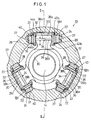
- reference numeral 10 indicates a constant velocity universal joint according to an embodiment of the present invention.
- the constant velocity universal joint 10 basically comprises a cylindrical outer cup (outer member) 12 integrally coupled to one end of an unillustrated driving shaft and having an opening, and an inner member 16 secured to one end of a driven shaft 14 and accommodated in a hole of the outer cup 12.
- Each of the guide grooves 18a (18b, 18c) comprises a plane section 20 formed at a substantially central portion, an inclined section 22 formed to be inclined on both sides of the plane section 20 at a predetermined angle, and a rolling surface 27 formed to be substantially perpendicular to the plane section 20, for allowing a roller member 24 described later on to roll thereon.
- a ring-shaped spider 30 is externally fitted to the driven shaft 14.
- Three trunnions 26a (26b, 26c), which expand toward the guide grooves 18a (18b, 18c) and are spaced apart from each other by an angle of 120 degrees about the axial center respectively, are secured to an outer circumferential surface of the spider 30.
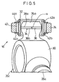
- Each of the trunnions 26a (26b, 26c) is formed to be spherical and surrounded by a cylindrical holder 32 with a predetermined clearance intervening therebetween.
- the trunnion 26a (26b, 26c) is tiltable within a predetermined angle with respect to the holder 32.
- An oil-reserving section which has a predetermined width A and extends along a direction substantially perpendicular to the axis, is formed at a portion having the longest circumference on the trunnion 26a (26b, 26c).
- the oil-reserving section is composed of a cutout 34 formed by chamfering the portion having the longest circumference on the surface of the trunnion 26a (26b, 26c).
- the cutout 34 comprises a circumferential section 36 having a substantially linear cross section formed by cutting out the spherical surface in the circumferential direction, and first and second annular ridges 38a, 38b provided at both ends of the circumferential section 36 along its widthwise direction to form boundaries between the circumferential section 36 and the spherical surface (see FIG. 3).
- the cutout 34 is formed such that it makes point-to-point contact at one or two points or makes line-to-line contact with the inner circumferential surface of the holder 32 as described later on.
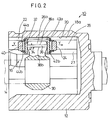
- An upper end of the holder 32 is formed such that the upper end is capable of abutting against and being separated from the plane section 20 of the guide groove 18a (18b, 18c). Namely, the upper end of the holder 32 is positioned, in an ordinary state, to have a slight clearance with respect to the plane section 20 of the guide groove 18a (18b, 18c). Further, the upper end of the holder 32 is formed to abut against the plane section 20 when the driving shaft or the driven shaft 14 is relatively inclined at a predetermined angle.
- the roller member 24 is externally fitted to an outer circumferential section of the holder 32 through a plurality of needle bearings 40.
- the roller member 24 has its outer circumferential surface with a cross section formed to be linear corresponding to the cross-sectional configuration of the guide groove 18a (18b, 18c).
- the respective needle bearings 40 and the roller member 24 are held by a set of circlips 42a, 42b and washers 44a, 44b fitted to annular grooves of the holder 32. It is possible to hold the needle bearings 40 and the roller member 24 only by using the circlips 42a, 42b without using the washers 44a, 44b.
- roller member 24 makes line-to-line contact with the rolling surface 27 of the guide groove 18a (18b, 18c).
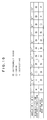
- the roller member 24 is slidable in its axial direction (in a direction indicated by an arrow X in FIG. 1).
- the roller member 24 is rollable laterally (in a direction indicated by an arrow Y in FIG. 2) along the rolling surface 27.
- the constant velocity universal joint 10 according to the embodiment of the present invention is basically constructed as described above. Now, the operation, function, and effect of the constant velocity universal joint 10 will be explained.
- the unillustrated driving shaft When the unillustrated driving shaft is rotated, its rotary driving force or torque is transmitted to the inner member 16 through the outer cup 12. Accordingly, the driven shaft 14 is rotated in a predetermined direction by the aid of the trunnions 26a to 26c formed to have the spherical configuration.
- the rotary driving force of the outer cup 12 is transmitted to the roller members 24 which are displaceable along the guide grooves 18a (18b, 18c).
- the force is further transmitted to the trunnions 26a (26b, 26c) through the holders 32 held by the roller members 24.
- the driven shaft 14 is rotated.
- FIGs. 4 to 7 show the change in state of inclination of the trunnion 26a (26b, 26c) at a predetermined angle with respect to the holder 32. It is assumed in FIGs. 4 to 7 that the driving torque is applied in a direction substantially perpendicular to the plane of the drawings, from the front to the back of the drawings.
- the inner circumferential surface having the columnar configuration of the holder 32 and the first and second annular ridges 38a, 38b of the trunnion 26a (26b, 26c) make point-to-point contact at two points of a point a 1 and a point a 2 .
- a clearance (for example, 70 ⁇ to 100 ⁇ ) is formed between the surface of the trunnion 26a (26b, 26c) and the inner circumferential surface of the holder 32 except for the point a 1 and the point a 2 . Accordingly, a lubricating oil enclosed in the outer cup 12 enters the clearance.
- an oil film formed by the lubricating oil is allowed to exist between the surface of the trunnion 26a (26b, 26c) and the inner circumferential surface of the holder 32.
- the surface of the trunnion 26a (26b, 26c) and the inner circumferential surface of the holder 32 are protected by the oil film respectively.
- the oil film for protecting the circumferential section 36 is not scraped off in the state shown in FIG. 4 because the circumferential section 36 does not contact with the inner circumferential surface of the holder 32.
- the surface of the trunnion 26a (26b, 26c) is not contacted with the inner circumferential surface of the holder 32 at all portions except for the line segment b.
- an oil film exists thereon, which is formed by the lubricating oil having entered the clearance.
- the oil film for protecting the second annular ridge 38b is not scraped off in the state shown in FIG. 6 because the second annular ridge 38b does not make contact with the inner circumferential surface of the holder 32.
- the holder 32 is not contacted with the trunnion 26a (26b, 26c) at all portions except for the point d as well.
- an oil film exists thereon, which is formed by the lubricating oil having entered the clearance.
- the inner circumferential surface of the holder 32 and the surface of the trunnion 26a (26b, 26c) undergo the change in contact state including the state of point-to-point contact at the two points (see FIG. 4), the state of line-to-line contact at the line segment b (see FIG. 5), and the state of point-to-point contact at the one point (see FIGs. 6 and 7), wherein the contact portion is protected by the oil film intervening between the surface of the holder 32 and the inner circumferential surface of the trunnion 26a (26b, 26c) in response to the foregoing change.
- the driving force can be more smoothly transmitted from the driving shaft to the driven shaft 14, and thus good transmitting efficiency can be obtained.
- the pressing force exerted on the inner circumferential surface of the holder 32 is dispersed owing to the change of the contact portion between the holder 32 and the trunnion 26a (26b, 26c) to make contact at the one point, two points, and line segment. Thus it is possible to restrain the pressing force.
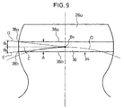
- a circle O which connects centers B 1 to B 3 of the plurality of the trunnions 26a, 26b, 26c, is drawn (see FIG. 8).
- a tangential line C which contacts with the circle O, is depicted.
- first and second phantom lines D, E which form angles ⁇ 1 and ⁇ 2 respectively, are drawn from the center B 1 (B 2 , B 3 ) of the trunnion 26a (26b, 26c) on the basis of the tangential line C.
- Intersections between the phantom lines D, E and the spherical surface of the trunnion 26a (26b, 26c) are designated as the first and second ridges 38a, 38b respectively.
- a spacing distance between the first and second ridges 38a, 38b is designated as the width A of the cutout 34 (circumferential section 36) (see FIG. 9).
- each of the angles of ⁇ 1 and ⁇ 2 is set to be in a range from 1 degree to 1.5 degree (the sum of the angles of ⁇ 1 and ⁇ 2 is 2 degrees to 3 degrees)
- the durability of the contact portion is deteriorated due to the frictional force generated between the trunnion 26a (26b, 26c) and the holder 32.
- each of the angles of ⁇ 1 and ⁇ 2 is preferably not less than about 2 degrees (the sum of the angles of ⁇ 1 and ⁇ 2 is not less than about 4 degrees).
- each of the angles of ⁇ 1 and ⁇ 2 is set to be not less than 9 degrees (the sum of the angles of ⁇ 1 and ⁇ 2 is not less than 18 degrees), backlash occurs due to the gap formed between the trunnion 26a (26b, 26c) and the holder 32. Accordingly, each of the angles of ⁇ 1 and ⁇ 2 is preferably not more than about 8 degrees (the sum of the angles of ⁇ 1 and ⁇ 2 is not more than about 16 degrees).
- the first and second annular ridges 38a, 38b are formed in a range in which each of the angles of ⁇ 1 and ⁇ 2 has a lower limit of about 2 degrees and an upper limit of about 8 degrees (the angle formed between the first and second phantom lines D, E in a plane including the tangential line C is in a range of about 4 degrees to about 16 degrees).
- the width A of the cutout 34 (circumferential section 36) is set by the spacing distance between the first and second ridges 38a, 38b.
- each of the angles of ⁇ 1 and ⁇ 2 is set to be less than 0.5 degree (the sum of the angles of ⁇ 1 and ⁇ 2 is less than 1 degree), the durability of the contact portion is deteriorated due to the frictional force generated between the trunnion 26a (26b, 26c) and the holder 32. Accordingly, each of the angles of ⁇ 1 and ⁇ 2 is preferably not less than about 0.5 degree (the sum of the angles of ⁇ 1 and ⁇ 2 is not less than about 1 degree).
- each of the angles of ⁇ 1 and ⁇ 2 is set to be not less than 9 degrees (the sum of the angles of ⁇ 1 and ⁇ 2 is not less than 18 degrees), backlash occurs due to the gap formed between the trunnion 26a (26b, 26c) and the holder 32. Accordingly, each of the angles of ⁇ 1 and ⁇ 2 is preferably not more than about 8 degrees (the sum of the angles of ⁇ 1 and ⁇ 2 is not more than about 16 degrees).
- the first and second annular ridges 38a, 38b are formed in a range in which each of the angles of ⁇ 1 and ⁇ 2 has a lower limit of about 0.5 degree and an upper limit of about 8 degrees (the angle formed between the first and second phantom lines D, E in a plane including the tangential line C is in a range of about 1 degrees to about 16 degrees).
- the width A of the cutout 34 (circumferential section 36) is preferably set by the spacing distance between the first and second ridges 38a, 38b.
- the width of the cutout 34 (circumferential section 36) can be decreased when the amount of the lubricating oil enclosed in the outer cup 12 is increased by a predetermined amount as compared with an ordinary state.
- a cutout 34 which extends in the direction substantially perpendicular to the axis of the trunnion 26a (26b, 26c).
- a cutout 34a may be provided, which extends along the axis of the trunnion 26a (26b, 26c).
- a cutout 34b may be provided, in which a circular flat section 46 is formed at the transmitting point for the driving force.
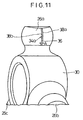
- the spherical surface may be formed with a substantially circular recess, or a substantially circular bulge 48 having a predetermined curvature exceeding a curvature of the spherical surface (see FIG. 13).
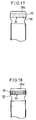
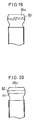
- FIGs. 15 to 22 Other modified embodiments of the oil-reserving section formed on the surface of the trunnion 26a (26b, 26c) are shown in FIGs. 15 to 22.
- a helical groove 50 is formed on the circumferential section 36 of the cutout 34 shown in FIG. 1.
- a sintered alloy 54 is embedded and formed in an annular groove 52 provided along the spherical surface.
- a plurality of irregularities 56 are formed by shot peening on the circumferential section 36 of the cutout 34 shown in FIG. 1.
- a plurality of linear grooves 58 are formed so that they are spaced apart from each other by a predetermined spacing along the circumferential section 36.
- a helical groove 60 is directly formed on the spherical surface of the trunnion 26a (26b, 26c) (FIG. 19).
- a sintered alloy 64 is embedded and formed in an annular groove 62 on the spherical trunnion 26a (26b, 26c) (FIG. 20).
- a plurality of irregularities 66 are formed by shot peening so that they encircle the spherical trunnion 26a (26b, 26c) along the circumferential direction (FIG. 21).
- a plurality of linear grooves 68 are formed so that they are spaced apart from each other by a predetermined spacing along the circumferential direction of the spherical surface of the trunnion 26a (26b, 26c) (FIG. 22).
- the lubricating performance for the holder 32 and the trunnion 26a is maintained by the lubricating oil reserved in the helical groove 60, the irregularities 66, or the groove 68, or by the lubricating oil seeped out from the sintered alloy.
- the entire spherical surface or the circumferential section 36 of the trunnion 26a may be subjected to, for example, formation of a molybdenum layer by means of plasma spraying with molybdenum (Mo), or subjected to, for example, application of composite dispersion plating treatment (for example, a surface is plated with a metal plating solution obtained by dispersing SiN therein), or sulphurizing nitriding treatment.
- Mo molybdenum
- composite dispersion plating treatment for example, a surface is plated with a metal plating solution obtained by dispersing SiN therein
- sulphurizing nitriding treatment for example, a surface is plated with a metal plating solution obtained by dispersing SiN therein
- the cutout 34 is formed to be flat.
- the cutout 34 may be formed as a recess which is concave with respect to the spherical surface.
- the cutout 34 may be formed as a bulge which has a predetermined curvature exceeding a curvature of the spherical surface.
Landscapes
- Engineering & Computer Science (AREA)
- General Engineering & Computer Science (AREA)
- Mechanical Engineering (AREA)
- General Details Of Gearings (AREA)
- Rolling Contact Bearings (AREA)
- Automatic Assembly (AREA)
- Pivots And Pivotal Connections (AREA)
- Vehicle Body Suspensions (AREA)
- Friction Gearing (AREA)
Priority Applications (1)
| Application Number | Priority Date | Filing Date | Title |
|---|---|---|---|
| EP99114697A EP0950823B1 (de) | 1996-02-15 | 1997-02-04 | Homokinetisches Kreuzgelenk |
Applications Claiming Priority (9)
| Application Number | Priority Date | Filing Date | Title |
|---|---|---|---|
| JP2807196 | 1996-02-15 | ||
| JP2807196 | 1996-02-15 | ||
| JP28071/96 | 1996-02-15 | ||
| JP6130796 | 1996-03-18 | ||
| JP61307/96 | 1996-03-18 | ||
| JP6130796 | 1996-03-18 | ||
| JP8238932A JP3043280B2 (ja) | 1996-02-15 | 1996-09-10 | 等速ジョイント |
| JP23893296 | 1996-09-10 | ||
| JP238932/96 | 1996-09-10 |
Related Child Applications (1)
| Application Number | Title | Priority Date | Filing Date |
|---|---|---|---|
| EP99114697A Division EP0950823B1 (de) | 1996-02-15 | 1997-02-04 | Homokinetisches Kreuzgelenk |
Publications (2)
| Publication Number | Publication Date |
|---|---|
| EP0790425A1 true EP0790425A1 (de) | 1997-08-20 |
| EP0790425B1 EP0790425B1 (de) | 2000-05-24 |
Family
ID=27286063
Family Applications (2)
| Application Number | Title | Priority Date | Filing Date |
|---|---|---|---|
| EP99114697A Expired - Lifetime EP0950823B1 (de) | 1996-02-15 | 1997-02-04 | Homokinetisches Kreuzgelenk |
| EP97101724A Expired - Lifetime EP0790425B1 (de) | 1996-02-15 | 1997-02-04 | Homokinetisches Kreuzgelenk |
Family Applications Before (1)
| Application Number | Title | Priority Date | Filing Date |
|---|---|---|---|
| EP99114697A Expired - Lifetime EP0950823B1 (de) | 1996-02-15 | 1997-02-04 | Homokinetisches Kreuzgelenk |
Country Status (10)
| Country | Link |
|---|---|
| US (1) | US5791995A (de) |
| EP (2) | EP0950823B1 (de) |
| JP (1) | JP3043280B2 (de) |
| CN (1) | CN1092301C (de) |
| CA (1) | CA2197403C (de) |
| DE (2) | DE69705966T2 (de) |
| ID (1) | ID15935A (de) |
| MX (1) | MX9701102A (de) |
| MY (1) | MY123107A (de) |
| TW (1) | TW436587B (de) |
Cited By (2)
| Publication number | Priority date | Publication date | Assignee | Title |
|---|---|---|---|---|
| FR2808311A1 (fr) * | 1999-01-12 | 2001-11-02 | Ntn Toyo Bearing Co Ltd | Joint homocinetique pour arbre de transmission |
| WO2010086434A1 (de) * | 2009-02-02 | 2010-08-05 | Tedrive Holding B.V. | Gleichlaufdrehgelenk mit verbesserten montageeigenschaften |
Families Citing this family (18)
| Publication number | Priority date | Publication date | Assignee | Title |
|---|---|---|---|---|
| WO1997029294A1 (en) * | 1996-02-05 | 1997-08-14 | Ntn Corporation | Tri-pot constant velocity universal joint |
| US6837794B1 (en) | 1996-02-05 | 2005-01-04 | Ntn Corporation | Tripod type constant velocity universal joint |
| US6198111B1 (en) * | 1998-10-14 | 2001-03-06 | Alara, Inc. | Scanning system with flexible drive assembly |
| EP1008778B1 (de) | 1998-12-08 | 2006-06-07 | Honda Giken Kogyo Kabushiki Kaisha | Homokinetisches Kreuzgelenk und Verfahren zur seiner Herstellung |
| JP4334754B2 (ja) * | 2000-10-13 | 2009-09-30 | デルファイ・テクノロジーズ・インコーポレーテッド | トリポード型等速ジョイント |
| WO2003036115A1 (en) * | 2001-10-26 | 2003-05-01 | Ntn Corporation | Tripod constant velocity universal joint |
| JP4133186B2 (ja) * | 2002-10-02 | 2008-08-13 | 株式会社ブリヂストン | 操舵輪用インホイールモータシステム |
| TWI298767B (en) * | 2002-10-25 | 2008-07-11 | Ntn Toyo Bearing Co Ltd | Tripod type constant velocity joint |
| JP4361351B2 (ja) * | 2003-11-14 | 2009-11-11 | Ntn株式会社 | トリポード型等速自在継手 |
| FR2864591B1 (fr) * | 2003-12-29 | 2007-04-13 | Gkn Driveline Sa | Joint de transmission homocinetique |
| JP2007090446A (ja) * | 2005-09-27 | 2007-04-12 | Nabeya Iron & Tool Works Ltd | 位置決めピン |
| US7435181B2 (en) * | 2005-10-25 | 2008-10-14 | Delphi Technologies, Inc. | Tripot ball with two point contact |
| KR100815677B1 (ko) * | 2006-05-11 | 2008-03-20 | 위아 주식회사 | 트라이포드식 등속조인트 |
| JP4926584B2 (ja) * | 2006-07-18 | 2012-05-09 | Ntn株式会社 | トリポード型等速自在継手 |
| WO2011074449A1 (ja) * | 2009-12-15 | 2011-06-23 | 本田技研工業株式会社 | 等速ジョイント |
| JP2013053691A (ja) * | 2011-09-05 | 2013-03-21 | Ntn Corp | 等速自在継手用外側継手部材およびその製造方法 |
| CN109296665A (zh) * | 2018-11-28 | 2019-02-01 | 马晓丰 | 一种轿车传动轴移动端节 |
| DE102024200008B3 (de) * | 2024-01-02 | 2025-06-12 | Volkswagen Aktiengesellschaft | Tripodestern für ein Tripodegelenk |
Citations (11)
| Publication number | Priority date | Publication date | Assignee | Title |
|---|---|---|---|---|
| JPS5469643A (en) * | 1977-11-11 | 1979-06-04 | Toyota Motor Corp | Tripod type joint |
| US4167860A (en) * | 1976-12-20 | 1979-09-18 | Toyota Jidosha Kogyo Kabushiki Kaisha | Universal joint |
| JPH01288625A (ja) * | 1988-05-16 | 1989-11-20 | Toyoda Mach Works Ltd | トリポード形等速ジョイント |
| WO1990006451A1 (en) * | 1988-11-26 | 1990-06-14 | Hardy Spicer Limited | Constant velocity ratio universal joints |
| DE4034805C1 (de) * | 1990-11-02 | 1991-11-21 | Gkn Automotive Ag, 5200 Siegburg, De | |
| GB2252144A (en) * | 1991-01-24 | 1992-07-29 | Sobhy Labib Girguis | Constant velocity universal joint |
| JPH04282028A (ja) | 1990-11-02 | 1992-10-07 | Gkn Automot Ag | 三脚継手 |
| JPH05215141A (ja) | 1991-09-11 | 1993-08-24 | Gkn Automot Ag | トリポードジョイント |
| DE9218285U1 (de) * | 1992-12-08 | 1994-04-07 | Gkn Automotive Ag, 53721 Siegburg | Durch Umformen hergestelltes Werkstück |
| FR2698928A1 (fr) * | 1992-12-08 | 1994-06-10 | Gkn Automotive Ag | Joint universel homocinétique. |
| DE4408812A1 (de) * | 1993-03-24 | 1994-09-29 | Schaeffler Waelzlager Kg | Gelenklager |
Family Cites Families (6)
| Publication number | Priority date | Publication date | Assignee | Title |
|---|---|---|---|---|
| US1734925A (en) * | 1925-05-18 | 1929-11-05 | Gen Electric | Circuit connecter |
| FR2607883B1 (fr) * | 1986-12-05 | 1991-05-17 | Orain Michel | Joint de transmission telescopique, notamment pour vehicule |
| JPH0715289B2 (ja) * | 1986-12-23 | 1995-02-22 | 日本精工株式会社 | トリポツト形等速ジヨイント |
| US4810232A (en) * | 1987-01-28 | 1989-03-07 | General Motors Corporation | Telescopic tripot universal joint |
| JPH044321A (ja) * | 1990-04-19 | 1992-01-08 | Toyoda Mach Works Ltd | 等速ジョイント |
| JPH04145231A (ja) * | 1990-10-04 | 1992-05-19 | Sumitomo Metal Ind Ltd | 連続溶融めっき装置の浴中ロール駆動用動力伝達装置 |
-
1996
- 1996-09-10 JP JP8238932A patent/JP3043280B2/ja not_active Expired - Lifetime
-
1997
- 1997-02-04 EP EP99114697A patent/EP0950823B1/de not_active Expired - Lifetime
- 1997-02-04 DE DE69705966T patent/DE69705966T2/de not_active Expired - Fee Related
- 1997-02-04 EP EP97101724A patent/EP0790425B1/de not_active Expired - Lifetime
- 1997-02-04 DE DE69702082T patent/DE69702082T2/de not_active Expired - Lifetime
- 1997-02-05 CN CN97102167A patent/CN1092301C/zh not_active Expired - Lifetime
- 1997-02-05 MY MYPI97000448A patent/MY123107A/en unknown
- 1997-02-06 US US08/796,543 patent/US5791995A/en not_active Expired - Lifetime
- 1997-02-12 CA CA002197403A patent/CA2197403C/en not_active Expired - Fee Related
- 1997-02-12 MX MX9701102A patent/MX9701102A/es unknown
- 1997-02-14 ID IDP970420A patent/ID15935A/id unknown
- 1997-02-14 TW TW086101733A patent/TW436587B/zh not_active IP Right Cessation
Patent Citations (11)
| Publication number | Priority date | Publication date | Assignee | Title |
|---|---|---|---|---|
| US4167860A (en) * | 1976-12-20 | 1979-09-18 | Toyota Jidosha Kogyo Kabushiki Kaisha | Universal joint |
| JPS5469643A (en) * | 1977-11-11 | 1979-06-04 | Toyota Motor Corp | Tripod type joint |
| JPH01288625A (ja) * | 1988-05-16 | 1989-11-20 | Toyoda Mach Works Ltd | トリポード形等速ジョイント |
| WO1990006451A1 (en) * | 1988-11-26 | 1990-06-14 | Hardy Spicer Limited | Constant velocity ratio universal joints |
| DE4034805C1 (de) * | 1990-11-02 | 1991-11-21 | Gkn Automotive Ag, 5200 Siegburg, De | |
| JPH04282028A (ja) | 1990-11-02 | 1992-10-07 | Gkn Automot Ag | 三脚継手 |
| GB2252144A (en) * | 1991-01-24 | 1992-07-29 | Sobhy Labib Girguis | Constant velocity universal joint |
| JPH05215141A (ja) | 1991-09-11 | 1993-08-24 | Gkn Automot Ag | トリポードジョイント |
| DE9218285U1 (de) * | 1992-12-08 | 1994-04-07 | Gkn Automotive Ag, 53721 Siegburg | Durch Umformen hergestelltes Werkstück |
| FR2698928A1 (fr) * | 1992-12-08 | 1994-06-10 | Gkn Automotive Ag | Joint universel homocinétique. |
| DE4408812A1 (de) * | 1993-03-24 | 1994-09-29 | Schaeffler Waelzlager Kg | Gelenklager |
Non-Patent Citations (2)
| Title |
|---|
| PATENT ABSTRACTS OF JAPAN vol. 14, no. 069 (M - 932) 16 May 1990 (1990-05-16) * |
| PATENT ABSTRACTS OF JAPAN vol. 3, no. 93 (M - 068) 8 August 1979 (1979-08-08) * |
Cited By (3)
| Publication number | Priority date | Publication date | Assignee | Title |
|---|---|---|---|---|
| FR2808311A1 (fr) * | 1999-01-12 | 2001-11-02 | Ntn Toyo Bearing Co Ltd | Joint homocinetique pour arbre de transmission |
| WO2010086434A1 (de) * | 2009-02-02 | 2010-08-05 | Tedrive Holding B.V. | Gleichlaufdrehgelenk mit verbesserten montageeigenschaften |
| US8231475B2 (en) | 2009-02-02 | 2012-07-31 | Neapco Europe Gmbh | CV joint with mechanically efficient assembly properties |
Also Published As
| Publication number | Publication date |
|---|---|
| DE69705966T2 (de) | 2001-11-22 |
| JP3043280B2 (ja) | 2000-05-22 |
| EP0950823B1 (de) | 2001-08-01 |
| US5791995A (en) | 1998-08-11 |
| EP0950823A2 (de) | 1999-10-20 |
| CA2197403A1 (en) | 1997-08-16 |
| EP0950823A3 (de) | 1999-11-10 |
| TW436587B (en) | 2001-05-28 |
| MX9701102A (es) | 1998-04-30 |
| JPH09310723A (ja) | 1997-12-02 |
| ID15935A (id) | 1997-08-21 |
| CN1092301C (zh) | 2002-10-09 |
| DE69705966D1 (de) | 2001-09-06 |
| DE69702082D1 (de) | 2000-06-29 |
| MY123107A (en) | 2006-05-31 |
| EP0790425B1 (de) | 2000-05-24 |
| DE69702082T2 (de) | 2000-09-14 |
| CN1162704A (zh) | 1997-10-22 |
| CA2197403C (en) | 2002-04-30 |
Similar Documents
| Publication | Publication Date | Title |
|---|---|---|
| US5791995A (en) | Constant velocity universal joint | |
| KR100977450B1 (ko) | 트리포드형 등속 조인트 | |
| US4773890A (en) | Slidable-type homokinetic (universal) tripod joint | |
| EP0861992B1 (de) | Homokinetisches Kreuzgelenk | |
| US6454655B1 (en) | Constant velocity universal joint and method for assembling the same | |
| US6764407B2 (en) | Constant velocity joint | |
| MXPA97001102A (en) | Board cardan speed consta | |
| EP1707835A1 (de) | Homokinetisches gelenk | |
| EP1505308B1 (de) | Gleichlaufgelenk | |
| US7544131B2 (en) | Tripod-type constant velocity joint | |
| EP1225358A1 (de) | Homokinetisches Kreuzgelenk | |
| EP0298249A2 (de) | Teleskopisches Kreuzgelenk | |
| US5836822A (en) | Constant velocity universal joint | |
| US20200208685A1 (en) | Constant velocity joint | |
| US6752721B2 (en) | Constant velocity universal joint | |
| US6217454B1 (en) | Tripod type constant velocity joint | |
| EP4397877A1 (de) | Tripode-gleichlaufgelenk | |
| KR19980024137A (ko) | 일정속도의 유니버설 조인트 | |
| JP2002213478A (ja) | 等速ジョイント | |
| JP2002266888A (ja) | 等速ジョイント | |
| JPH10220487A (ja) | 等速ジョイント |
Legal Events
| Date | Code | Title | Description |
|---|---|---|---|
| PUAI | Public reference made under article 153(3) epc to a published international application that has entered the european phase |
Free format text: ORIGINAL CODE: 0009012 |
|
| 17P | Request for examination filed |
Effective date: 19970204 |
|
| AK | Designated contracting states |
Kind code of ref document: A1 Designated state(s): DE FR GB |
|
| 17Q | First examination report despatched |
Effective date: 19980324 |
|
| GRAG | Despatch of communication of intention to grant |
Free format text: ORIGINAL CODE: EPIDOS AGRA |
|
| GRAG | Despatch of communication of intention to grant |
Free format text: ORIGINAL CODE: EPIDOS AGRA |
|
| GRAH | Despatch of communication of intention to grant a patent |
Free format text: ORIGINAL CODE: EPIDOS IGRA |
|
| GRAH | Despatch of communication of intention to grant a patent |
Free format text: ORIGINAL CODE: EPIDOS IGRA |
|
| GRAA | (expected) grant |
Free format text: ORIGINAL CODE: 0009210 |
|
| AK | Designated contracting states |
Kind code of ref document: B1 Designated state(s): DE FR GB |
|
| REF | Corresponds to: |
Ref document number: 69702082 Country of ref document: DE Date of ref document: 20000629 |
|
| ET | Fr: translation filed | ||
| PLBE | No opposition filed within time limit |
Free format text: ORIGINAL CODE: 0009261 |
|
| STAA | Information on the status of an ep patent application or granted ep patent |
Free format text: STATUS: NO OPPOSITION FILED WITHIN TIME LIMIT |
|
| 26N | No opposition filed | ||
| REG | Reference to a national code |
Ref country code: GB Ref legal event code: IF02 |
|
| REG | Reference to a national code |
Ref country code: FR Ref legal event code: PLFP Year of fee payment: 20 |
|
| PGFP | Annual fee paid to national office [announced via postgrant information from national office to epo] |
Ref country code: DE Payment date: 20160127 Year of fee payment: 20 |
|
| PGFP | Annual fee paid to national office [announced via postgrant information from national office to epo] |
Ref country code: FR Payment date: 20160108 Year of fee payment: 20 Ref country code: GB Payment date: 20160203 Year of fee payment: 20 |
|
| REG | Reference to a national code |
Ref country code: DE Ref legal event code: R071 Ref document number: 69702082 Country of ref document: DE |
|
| REG | Reference to a national code |
Ref country code: GB Ref legal event code: PE20 Expiry date: 20170203 |
|
| PG25 | Lapsed in a contracting state [announced via postgrant information from national office to epo] |
Ref country code: GB Free format text: LAPSE BECAUSE OF EXPIRATION OF PROTECTION Effective date: 20170203 |