EP0790478A2 - Machine de mesure coordonnées avec palpeur orientable - Google Patents
Machine de mesure coordonnées avec palpeur orientable Download PDFInfo
- Publication number
- EP0790478A2 EP0790478A2 EP97101083A EP97101083A EP0790478A2 EP 0790478 A2 EP0790478 A2 EP 0790478A2 EP 97101083 A EP97101083 A EP 97101083A EP 97101083 A EP97101083 A EP 97101083A EP 0790478 A2 EP0790478 A2 EP 0790478A2
- Authority
- EP
- European Patent Office
- Prior art keywords
- stylus
- coordinate measuring
- probe
- joint
- machine
- Prior art date
- Legal status (The legal status is an assumption and is not a legal conclusion. Google has not performed a legal analysis and makes no representation as to the accuracy of the status listed.)
- Granted
Links
- 239000000523 sample Substances 0.000 claims description 57
- 241001422033 Thestylus Species 0.000 claims description 45
- 238000000034 method Methods 0.000 claims description 16
- 241000289669 Erinaceus europaeus Species 0.000 claims description 3
- 230000002401 inhibitory effect Effects 0.000 claims 2
- 238000005259 measurement Methods 0.000 abstract description 3
- 208000031872 Body Remains Diseases 0.000 abstract 1
- 238000013461 design Methods 0.000 description 3
- XEEYBQQBJWHFJM-UHFFFAOYSA-N Iron Chemical compound [Fe] XEEYBQQBJWHFJM-UHFFFAOYSA-N 0.000 description 2
- 238000010586 diagram Methods 0.000 description 1
- 229910052742 iron Inorganic materials 0.000 description 1
- 238000012360 testing method Methods 0.000 description 1
- 238000012549 training Methods 0.000 description 1
Images


Classifications
-
- G—PHYSICS
- G01—MEASURING; TESTING
- G01B—MEASURING LENGTH, THICKNESS OR SIMILAR LINEAR DIMENSIONS; MEASURING ANGLES; MEASURING AREAS; MEASURING IRREGULARITIES OF SURFACES OR CONTOURS
- G01B21/00—Measuring arrangements or details thereof, where the measuring technique is not covered by the other groups of this subclass, unspecified or not relevant
- G01B21/02—Measuring arrangements or details thereof, where the measuring technique is not covered by the other groups of this subclass, unspecified or not relevant for measuring length, width, or thickness
- G01B21/04—Measuring arrangements or details thereof, where the measuring technique is not covered by the other groups of this subclass, unspecified or not relevant for measuring length, width, or thickness by measuring coordinates of points
- G01B21/047—Accessories, e.g. for positioning, for tool-setting, for measuring probes
-
- G—PHYSICS
- G01—MEASURING; TESTING
- G01B—MEASURING LENGTH, THICKNESS OR SIMILAR LINEAR DIMENSIONS; MEASURING ANGLES; MEASURING AREAS; MEASURING IRREGULARITIES OF SURFACES OR CONTOURS
- G01B5/00—Measuring arrangements characterised by the use of mechanical techniques
- G01B5/004—Measuring arrangements characterised by the use of mechanical techniques for measuring coordinates of points
- G01B5/008—Measuring arrangements characterised by the use of mechanical techniques for measuring coordinates of points using coordinate measuring machines
- G01B5/012—Contact-making feeler heads therefor
-
- Y—GENERAL TAGGING OF NEW TECHNOLOGICAL DEVELOPMENTS; GENERAL TAGGING OF CROSS-SECTIONAL TECHNOLOGIES SPANNING OVER SEVERAL SECTIONS OF THE IPC; TECHNICAL SUBJECTS COVERED BY FORMER USPC CROSS-REFERENCE ART COLLECTIONS [XRACs] AND DIGESTS
- Y10—TECHNICAL SUBJECTS COVERED BY FORMER USPC
- Y10S—TECHNICAL SUBJECTS COVERED BY FORMER USPC CROSS-REFERENCE ART COLLECTIONS [XRACs] AND DIGESTS
- Y10S33/00—Geometrical instruments
- Y10S33/01—Magnetic
Definitions
- the invention relates to a coordinate measuring machine with a stylus, the spatial orientation of which can be set under machine control.
- coordinate measuring machines usually have a so-called “active swivel joint", via which the stylus or the probe itself is attached to the measuring arm of the coordinate measuring machine.
- the "active swivel joint” contains separate drives for the two swivel or swivel axes.
- Such an active swivel joint is also described, for example, in DE 37 40 070 and the corresponding US Pat. No. 4,888,877.
- a disadvantage here is the not inconsiderable effort that has to be driven for the drives, the sensors for the feedback of the position of the stylus, etc., especially if additional value is placed on the most compact possible design of the swivel joint.
- the probes themselves are pivoted with such active rotary swivel joints, while it is very difficult to pivot the stylus alone. Because then the weight of the rotary swivel joint would have to be designed so that it clearly falls below the maximum permissible mass for the deflectable stylus in the probe.
- a passive swivel joint is also known from DE 28 04 398.
- the probe is attached to the measuring arm of the coordinate measuring machine via an articulated connection provided with catches or friction springs.
- the probe can then be brought into a different spatial orientation by the measuring machine traversing the shaft of the probe against an obstacle, for example an edge on the workpiece or a separate obstacle placed on the table of the CMM for this purpose, so that the shaft is then at Continue driving from the vertical to a horizontal position.
- a device is attached in the working area of the coordinate measuring machine, from which the shaped probe body, i.e. the ball of the stylus can be centered.
- the rotational or pivoting axis is unclamped and then moved on circular paths in relation to the position of the shaped probe body as the center point.
- the device for centering the shaped probe body is provided on its surface with a large number of centering points, which can be done, for example, by the body being constructed in the manner of a hedgehog or a morning star, or in that the centering points consist of a large number of side by side spherical Bodies such as spheres or hemispheres are formed.
- the centering receptacle also being able to be changed between the individual processes. In this way it is also possible to work with centering fixtures which only allow keying in from a limited angular range.
- the stylus is expediently pivotable about two mutually perpendicular axes, which axes can be formed by a gimbal or, for example, by a spherical bearing. It is particularly advantageous if this bearing can be clamped under machine control or unclamped for the process of reorienting the stylus alignment. This can be done, for example, by a device which is constructed from a permanent magnet and an electromagnet, as described in DE-PS 34 34 116.
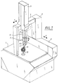
- the coordinate measuring machine shown in Figure 1 is of the so-called portal type.
- the bridge-shaped portal designated there with (3) is e.g. is supported by air bearings with one foot on the measuring table (1) and with the other foot on the guideway (2) attached to it, motor-driven in the direction of the arrow denoted by (y).
- the cross slide (5) is movably mounted on the cross beam (4) designed as an x-guide.
- the designated (6), actual measuring arm, the so-called quill is vertically (z) slidably guided in the cross slide (5) and carries on its underside a so-called “measuring" probe (7) on which the actual stylus (9) with its Probe ball (19) is attached via a passive swivel joint (8).
- the probe (7) can be, for example, the probe described in DE-OS 44 24 225.5, formed from three parallelogram guides built on one another.
- the structure of the rotary swivel joint (8) is shown in more detail in FIG. 4. It essentially consists of a ball joint, the ball (12), to which a receptacle (11) for the stylus (9) is attached, in an annular bearing socket (13) lies.
- a cylindrical body (14) is used to clamp the ball, which is guided straight in the housing (8) and is pressed in the direction of the annular bearing (13) by a helical spring (16). It has a conical bore (15) on its underside, which presses on the spherical surface.
- the body (14) consists of soft iron at least in the upper part.
- a switching magnet is used coaxially to the spring (16), which consists of a permanent magnet (18) and an electromagnet (17) placed around it.
- the field of the permanent magnet (18) can be strengthened by a short current surge in such a way that the part (14) is attracted to the permanent magnet (18), where it sticks until it is thrown off again by a current pulse of opposite polarity.
- a centering body (10) is built up at one point in the measuring area of the coordinate measuring machine, as can be seen in FIG. 1 and in the enlarged representation according to FIG. This has in the manner of a hedgehog or morning star on its spherical surface a large number of outwardly directed tips, which are so close together that there are recesses between the tips into which the probe ball (19) can feel in a self-centering manner.
- the ball (12) is unclamped in the passive swivel joint (8).
- the coordinate measuring machine then moves the center of the ball (12) on a circular path around the center of the probe ball (19) by simultaneously actuating at least two drives. This is explained in more detail in FIG. 2.
- (29) denotes the point in the swivel joint (8) about which the stylus (9) can be rotated or pivoted. Its distance (a) from the center of the probe ball (19) is known and can be determined, for example, by calibration on a test standard.
- either the computer of the coordinate measuring machine or a microprocessor in the control of the machine calculates the arc (K1) or (K2) from this distance (a) and the desired swivel angle ( ⁇ , ⁇ ) on which the intersection (29 ) the rotation or swivel axes must be moved with the center of the probe ball (19) fixed, so that the desired swivel angle (8) or rotation angle ( ⁇ ) results.
- the control moves the measuring slides in two coordinates (x) and (z) or (x) and (y) simultaneously.
- the probe ball (19) remains in the centering gap formed by the two tips (10a) and (10b) and a further tip (10c), which is not visible here, while the orientation of the stylus (9) changes.
- the above-described pivoting process of the probe with the help of the drives of the coordinate measuring machine can always be carried out "in one go” as long as the pivoting angle does not become too large and exceeds the opening angle of the centering gap into which the keying is made.
- balls (20a, 20b) with a smaller diameter can also be glued onto the surface of a larger ball (20), for example, as shown in FIG. 6, or conical bores can be drilled into the ball surface.
- a passive, latching rotary swivel joint can be used, as is outlined in FIG. 5.
- the surface of the ball (22) of the bearing of the joint is provided with a large number of conical bores and a central bore is made in the underside of the part (24) serving for clamping, in which a latching ball (31) and a spring (30) is added.
- the spring (30) has a much lower spring constant than the spring (26) with which the part (24) is pressed against the ball (22) of the bearing. In this way, in the unclamped state, the ball (22) can be latched into discrete angular positions without great force with the attached stylus (9) before this position is then subsequently fixed. This is done by loosening the part (24) with the aid of the combined electromagnet (27) and permanent magnet (28) and pressing it onto the surface of the ball (22) by the spring (26) for the purpose of clamping.
- a ball joint for storing the stylus.
- a universal joint or any other joint can be used, which has at least one, but preferably two axes of rotation or swivel. These axes must do not necessarily intersect at one point. Because even if the axes are spaced apart, they can each be moved on circular arcs, but with different diameters, with respect to the center of the probe ball.
- the spherical bearing described in DE-OS 44 35 401 can, for example, also be used as a bearing for the stylus.
- the joint does not necessarily have to be moved on circular paths, even if this is an advantageous embodiment. Any other lanes are of course also possible. Ultimately, it is only decisive that the joint is moved so that the shaped probe body (19) remains centered in the device (10).
Landscapes
- Physics & Mathematics (AREA)
- General Physics & Mathematics (AREA)
- A Measuring Device Byusing Mechanical Method (AREA)
- Length Measuring Devices With Unspecified Measuring Means (AREA)
Applications Claiming Priority (2)
| Application Number | Priority Date | Filing Date | Title |
|---|---|---|---|
| DE19605776A DE19605776A1 (de) | 1996-02-16 | 1996-02-16 | Koordinatenmeßgerät mit einem Taststift, dessen Orientierung einstellbar ist |
| DE19605776 | 1996-02-16 |
Publications (3)
| Publication Number | Publication Date |
|---|---|
| EP0790478A2 true EP0790478A2 (fr) | 1997-08-20 |
| EP0790478A3 EP0790478A3 (fr) | 1999-05-19 |
| EP0790478B1 EP0790478B1 (fr) | 2001-12-19 |
Family
ID=7785589
Family Applications (1)
| Application Number | Title | Priority Date | Filing Date |
|---|---|---|---|
| EP97101083A Expired - Lifetime EP0790478B1 (fr) | 1996-02-16 | 1997-01-24 | Machine de mesure coordonnées avec palpeur orientable |
Country Status (3)
| Country | Link |
|---|---|
| US (1) | US5848477A (fr) |
| EP (1) | EP0790478B1 (fr) |
| DE (2) | DE19605776A1 (fr) |
Cited By (6)
| Publication number | Priority date | Publication date | Assignee | Title |
|---|---|---|---|---|
| WO2007058610A1 (fr) | 2005-11-17 | 2007-05-24 | Hexagon Metrology Ab | Dispositif de reglage pour tete de mesure |
| DE102005063242B4 (de) * | 2005-12-20 | 2011-01-13 | Carl Zeiss Industrielle Messtechnik Gmbh | Magnetkupplung, insbesondere zum Arretieren eines Drehgelenks bei einem Koordinatenmessgerät |
| DE102017114551A1 (de) | 2017-06-29 | 2019-01-03 | Carl Zeiss Industrielle Messtechnik Gmbh | Dreh-Schwenk-Mechanismus für ein Koordinatenmessgerät |
| DE102018115745A1 (de) | 2018-06-29 | 2020-01-02 | Carl Zeiss Industrielle Messtechnik Gmbh | Dreh-Schwenk-Mechanismus für ein Koordinatenmessgerät |
| EP3722740A1 (fr) | 2019-04-08 | 2020-10-14 | Carl Zeiss Industrielle Messtechnik GmbH | Procédé et dispositif informatique permettant de sélectionner une séquence de mesure pour un appareil de mesure de coordonnées |
| EP3129750B1 (fr) | 2014-04-08 | 2023-05-31 | Nikon Metrology NV | Unité de sonde de mesure pour des applications métrologiques |
Families Citing this family (32)
| Publication number | Priority date | Publication date | Assignee | Title |
|---|---|---|---|---|
| DE19712029A1 (de) * | 1997-03-21 | 1998-09-24 | Zeiss Carl Fa | Verfahren zur Steuerung von Koordinatenmeßgeräten nach Solldaten |
| US6598308B1 (en) * | 1997-11-28 | 2003-07-29 | Jne Ab | Measuring system |
| US5979070A (en) * | 1997-12-19 | 1999-11-09 | Lau; Kam C. | Method and apparatus for selectively locking a movement direction of a coordinate measurement probe |
| IT1299955B1 (it) | 1998-04-06 | 2000-04-04 | Marposs Spa | Testa per il controllo di dimensioni lineari di pezzi. |
| GB9813263D0 (en) * | 1998-06-20 | 1998-08-19 | Renishaw Plc | Touch probe |
| JP3633788B2 (ja) * | 1998-07-13 | 2005-03-30 | 株式会社ミツトヨ | 測定装置 |
| US6178654B1 (en) * | 1999-02-18 | 2001-01-30 | Ball Semiconductor, Inc. | Method and system for aligning spherical-shaped objects |
| DE29903815U1 (de) | 1999-02-22 | 1999-07-15 | Herz System- und Anlagentechnik GmbH, 29499 Zernien | Vorrichtung zur Steuerung des relativen Hubs eines an Objekten angreifenden Hubgeräts |
| US6536121B1 (en) * | 1999-08-06 | 2003-03-25 | Thk Co., Ltd. | Scribing apparatus |
| US6265234B1 (en) | 2000-01-25 | 2001-07-24 | Ball Semiconductor, Inc. | Alignment system for a spherical device |
| US6810600B1 (en) * | 2000-02-02 | 2004-11-02 | Unova Ip Corp. | Apparatus and method for monitoring alignment of a CNC machine spindle trunnion axis A |
| KR100441338B1 (ko) * | 2001-04-02 | 2004-07-23 | 헌 김 | 데이터 입력장치 |
| DE10122200A1 (de) * | 2001-05-08 | 2002-11-14 | Zeiss Carl | Tastkopf für ein Koordinatenmeßgerät. Koordinatenmeßgerät, Kalibrierkörper für ein Koordinatenmeßgerät und Verfahren zum Kalibrieren eines Koordinatenmeßgerätes |
| GB0114360D0 (en) * | 2001-06-13 | 2001-08-08 | Renishaw Plc | Stylus orientation |
| SE524543C2 (sv) * | 2002-01-17 | 2004-08-24 | Jne Ab | Mätlinjal, avsedd för symmetrimätningar på fordon |
| GB0215152D0 (en) * | 2002-07-01 | 2002-08-07 | Renishaw Plc | Probe or stylus orientation |
| DE10260670B4 (de) * | 2002-12-23 | 2007-04-05 | Carl Zeiss Industrielle Messtechnik Gmbh | Vorrichtung zum optischen Abtasten von Werkstücken |
| US20040207417A1 (en) * | 2003-04-16 | 2004-10-21 | Barr Andrew Harvey | Electronic probe with positionable tip |
| DE102005017708A1 (de) * | 2005-04-15 | 2006-10-19 | Wolfgang Madlener | Verfahren und Vorrichtung zum Vermessen von Werkstücken mit einem Messtaster an einer Werkzeugmaschine |
| JP5179760B2 (ja) * | 2007-02-05 | 2013-04-10 | 株式会社ミツトヨ | 座標測定用補助具、座標測定用プローブ及び座標測定機 |
| DE102007022326B4 (de) | 2007-05-08 | 2022-07-07 | Carl Zeiss Industrielle Messtechnik Gmbh | Koordinatenmessgerät zum Bestimmen von Raumkoordinaten an einem Messobjekt sowie Dreh-Schwenk-Mechanismus für ein solches Koordinatenmessgerät |
| US8024853B2 (en) * | 2007-12-19 | 2011-09-27 | Hitachi Global Storage Technologies, Netherlands B.V. | Head gimbal assembly (HGA) connector pad alignment jig |
| GB0804114D0 (en) * | 2008-03-05 | 2008-04-09 | Renishaw Plc | Surface sensing device |
| JP5269698B2 (ja) * | 2009-06-10 | 2013-08-21 | 株式会社ミツトヨ | 真円度測定装置 |
| DE102010006505B4 (de) | 2010-01-28 | 2013-09-19 | Carl Zeiss Industrielle Messtechnik Gmbh | Koordinatenmessgerät mit passivem Dreh-Schwenk-Mechanismus |
| GB201012249D0 (en) * | 2010-07-21 | 2010-09-08 | Renishaw Plc | Metrology apparatus |
| US9279441B2 (en) | 2010-09-10 | 2016-03-08 | Carl Zeiss 3D Automation Gmbh | Tracer pin arrangement |
| GB2493214B (en) * | 2011-07-29 | 2016-06-08 | Taylor Hobson Ltd | Metrological apparatus |
| DE102012003321B4 (de) | 2012-02-18 | 2015-07-23 | Federal-Mogul Burscheid Gmbh | Einrichtung zur Vermessung von Kolbenringen |
| JP6518421B2 (ja) * | 2014-09-24 | 2019-05-22 | 株式会社ミツトヨ | 真円度測定機およびその制御方法 |
| DE102015206308A1 (de) * | 2015-04-09 | 2016-10-13 | Carl Zeiss 3D Automation Gmbh | Taststifthalter |
| EP3184960B1 (fr) * | 2015-12-22 | 2018-06-27 | Tesa Sa | Tête orientable motorisée pour système de mesure |
Citations (4)
| Publication number | Priority date | Publication date | Assignee | Title |
|---|---|---|---|---|
| DE2804398A1 (de) | 1977-02-07 | 1978-08-17 | Renishaw Electrical Ltd | Koordinatenmessmaschine und verfahren zu deren betrieb |
| DE3434116A1 (de) | 1984-09-17 | 1986-03-27 | Fa. Carl Zeiss, 7920 Heidenheim | Elektromagnetische bremse |
| US4888877A (en) | 1987-11-26 | 1989-12-26 | Carl-Zeiss-Stiftung, Heidenhein/Brenz | Articulating head for a coordinate-measuring instrument |
| DE4435401A1 (de) | 1993-10-13 | 1995-04-20 | Max Oschwald | Sphärische Aufhängung für ein technisches Instrument |
Family Cites Families (7)
| Publication number | Priority date | Publication date | Assignee | Title |
|---|---|---|---|---|
| US4523450A (en) * | 1981-11-07 | 1985-06-18 | Carl-Zeiss-Stiftung, Heidenheim/Brenz | Method of calibrating probe pins on multicoordinate measurement machines |
| DE3621626A1 (de) * | 1986-06-27 | 1988-01-14 | Zeiss Carl Fa | Halter fuer taststifte |
| GB2203837B (en) * | 1987-04-06 | 1991-02-20 | Mitutoyo Corp | Apparatus and method for spatial coordinate measurement |
| GB8906287D0 (en) * | 1989-03-18 | 1989-05-04 | Renishaw Plc | Probe calibration |
| DE69003149T2 (de) * | 1989-04-14 | 1994-01-05 | Renishaw Plc | Tastkopf. |
| US5251156A (en) * | 1990-08-25 | 1993-10-05 | Carl-Zeiss-Stiftung, Heidenheim/Brenz | Method and apparatus for non-contact measurement of object surfaces |
| DE4424225A1 (de) * | 1994-07-09 | 1996-01-11 | Zeiss Carl Fa | Tastkopf für Koordinatenmeßgeräte |
-
1996
- 1996-02-16 DE DE19605776A patent/DE19605776A1/de not_active Withdrawn
-
1997
- 1997-01-24 EP EP97101083A patent/EP0790478B1/fr not_active Expired - Lifetime
- 1997-01-24 DE DE59705831T patent/DE59705831D1/de not_active Expired - Lifetime
- 1997-02-11 US US08/798,540 patent/US5848477A/en not_active Expired - Fee Related
Patent Citations (4)
| Publication number | Priority date | Publication date | Assignee | Title |
|---|---|---|---|---|
| DE2804398A1 (de) | 1977-02-07 | 1978-08-17 | Renishaw Electrical Ltd | Koordinatenmessmaschine und verfahren zu deren betrieb |
| DE3434116A1 (de) | 1984-09-17 | 1986-03-27 | Fa. Carl Zeiss, 7920 Heidenheim | Elektromagnetische bremse |
| US4888877A (en) | 1987-11-26 | 1989-12-26 | Carl-Zeiss-Stiftung, Heidenhein/Brenz | Articulating head for a coordinate-measuring instrument |
| DE4435401A1 (de) | 1993-10-13 | 1995-04-20 | Max Oschwald | Sphärische Aufhängung für ein technisches Instrument |
Cited By (10)
| Publication number | Priority date | Publication date | Assignee | Title |
|---|---|---|---|---|
| WO2007058610A1 (fr) | 2005-11-17 | 2007-05-24 | Hexagon Metrology Ab | Dispositif de reglage pour tete de mesure |
| EP1949028A4 (fr) * | 2005-11-17 | 2010-04-14 | Hexagon Metrology Ab | Dispositif de reglage pour tete de mesure |
| DE102005063242B4 (de) * | 2005-12-20 | 2011-01-13 | Carl Zeiss Industrielle Messtechnik Gmbh | Magnetkupplung, insbesondere zum Arretieren eines Drehgelenks bei einem Koordinatenmessgerät |
| EP3129750B1 (fr) | 2014-04-08 | 2023-05-31 | Nikon Metrology NV | Unité de sonde de mesure pour des applications métrologiques |
| DE102017114551A1 (de) | 2017-06-29 | 2019-01-03 | Carl Zeiss Industrielle Messtechnik Gmbh | Dreh-Schwenk-Mechanismus für ein Koordinatenmessgerät |
| US10788303B2 (en) | 2017-06-29 | 2020-09-29 | Carl Zeiss Industrielle Messtechnik Gmbh | Sensor adjustment mechanism for a coordinate measuring machine |
| DE102017114551B4 (de) | 2017-06-29 | 2021-12-23 | Carl Zeiss Industrielle Messtechnik Gmbh | Dreh-Schwenk-Mechanismus für ein Koordinatenmessgerät |
| DE102018115745A1 (de) | 2018-06-29 | 2020-01-02 | Carl Zeiss Industrielle Messtechnik Gmbh | Dreh-Schwenk-Mechanismus für ein Koordinatenmessgerät |
| DE102018115745B4 (de) | 2018-06-29 | 2024-12-05 | Carl Zeiss Industrielle Messtechnik Gmbh | Dreh-Schwenk-Mechanismus für ein Koordinatenmessgerät |
| EP3722740A1 (fr) | 2019-04-08 | 2020-10-14 | Carl Zeiss Industrielle Messtechnik GmbH | Procédé et dispositif informatique permettant de sélectionner une séquence de mesure pour un appareil de mesure de coordonnées |
Also Published As
| Publication number | Publication date |
|---|---|
| DE19605776A1 (de) | 1997-08-21 |
| EP0790478B1 (fr) | 2001-12-19 |
| EP0790478A3 (fr) | 1999-05-19 |
| US5848477A (en) | 1998-12-15 |
| DE59705831D1 (de) | 2002-01-31 |
Similar Documents
| Publication | Publication Date | Title |
|---|---|---|
| EP0790478B1 (fr) | Machine de mesure coordonnées avec palpeur orientable | |
| EP0703517B1 (fr) | Procédé de mesure de pièces à l'aide d'un appareil de mesure de coordonnées déplacé manuellement | |
| EP0317967B1 (fr) | Dispositif permettant la déflection-rotation du palpeur de machines de mesure de coordonnées | |
| DE4238139C2 (de) | Koordinatenmeßgerät | |
| DE2804398B2 (de) | MeBkopf für KoordinatenmeBmaschinen | |
| EP0332575B1 (fr) | Palpeur produisant une valeur de mesure en touchant une pièce à usiner | |
| EP0789221B1 (fr) | Méthode et dispositif pour mesurer les coordonnées de pièces usinées sur des machines-outils | |
| EP1696289A1 (fr) | Procédé pour dimensionner une machine-outil | |
| EP0686829A2 (fr) | Appareil de mesure pour le contrÔle des dimensions de pièces cylindriques | |
| DE3725207A1 (de) | Tastkopf fuer koordinatenmessgeraete | |
| DE102019115630B3 (de) | Schwenktaster | |
| DE3613096A1 (de) | Verfahren zum bearbeiten von werkstuecken | |
| DE102017105814B3 (de) | System zum Messen der Rauheit einer Oberfläche eines Werkstücks | |
| DE10239694A1 (de) | Verfahren zur Kalibrierung eines Fräsers | |
| DE19708762B4 (de) | Verfahren zum Konfigurieren einer Vorrichtung für die Positionierung von Bauteilen auf einer Maschine | |
| EP0729005B1 (fr) | Dispositif de mesure pour la vérification de la précision géométrique et dynamique des machines-outil NC et des robots industriels | |
| EP3314203A1 (fr) | Élément adapteur pour le montage d'un dispositif rotatif dans la chambre de mesure d'un appareil de mesure de coordonnées | |
| DE102020114673B3 (de) | Sphärischer Parallelmanipulator, Schwenkeinrichtung und Messgerät | |
| DE102022117995A1 (de) | Rundheitsmessmaschine | |
| DE102019205145A1 (de) | Ausrichten von Komponenten relativ zu einem Koordinatenmessgerät | |
| EP1405036B1 (fr) | Procede pour actionner un appareil de mesure de coordonnees comportant une articulation tournante-pivotante | |
| DE4315161A1 (de) | Vorrichtung zum Vermessen von Bauteilen mittels eines Tasters | |
| DE4100396A1 (de) | Tastmessgeraet | |
| EP3123105B1 (fr) | Dispositif et procédé pour mesurer une pièce | |
| DE10240700A1 (de) | Koordinatenmessgerät sowie Verfahren zur Rundheitsmessung an einem Werkstück mit diesem Koordinatenmessgerät |
Legal Events
| Date | Code | Title | Description |
|---|---|---|---|
| PUAI | Public reference made under article 153(3) epc to a published international application that has entered the european phase |
Free format text: ORIGINAL CODE: 0009012 |
|
| AK | Designated contracting states |
Kind code of ref document: A2 Designated state(s): DE FR GB IT |
|
| PUAL | Search report despatched |
Free format text: ORIGINAL CODE: 0009013 |
|
| AK | Designated contracting states |
Kind code of ref document: A3 Designated state(s): DE FR GB IT |
|
| 17P | Request for examination filed |
Effective date: 19991019 |
|
| GRAG | Despatch of communication of intention to grant |
Free format text: ORIGINAL CODE: EPIDOS AGRA |
|
| 17Q | First examination report despatched |
Effective date: 20010214 |
|
| RAP1 | Party data changed (applicant data changed or rights of an application transferred) |
Owner name: CARL-ZEISS-STIFTUNG, TRADING AS CARL ZEISS Owner name: CARL ZEISS |
|
| GRAG | Despatch of communication of intention to grant |
Free format text: ORIGINAL CODE: EPIDOS AGRA |
|
| GRAH | Despatch of communication of intention to grant a patent |
Free format text: ORIGINAL CODE: EPIDOS IGRA |
|
| GRAH | Despatch of communication of intention to grant a patent |
Free format text: ORIGINAL CODE: EPIDOS IGRA |
|
| GRAA | (expected) grant |
Free format text: ORIGINAL CODE: 0009210 |
|
| AK | Designated contracting states |
Kind code of ref document: B1 Designated state(s): DE FR GB IT |
|
| REG | Reference to a national code |
Ref country code: GB Ref legal event code: IF02 |
|
| REF | Corresponds to: |
Ref document number: 59705831 Country of ref document: DE Date of ref document: 20020131 |
|
| GBT | Gb: translation of ep patent filed (gb section 77(6)(a)/1977) |
Effective date: 20020311 |
|
| PLBE | No opposition filed within time limit |
Free format text: ORIGINAL CODE: 0009261 |
|
| STAA | Information on the status of an ep patent application or granted ep patent |
Free format text: STATUS: NO OPPOSITION FILED WITHIN TIME LIMIT |
|
| 26N | No opposition filed | ||
| REG | Reference to a national code |
Ref country code: GB Ref legal event code: 732E |
|
| PGFP | Annual fee paid to national office [announced via postgrant information from national office to epo] |
Ref country code: IT Payment date: 20090128 Year of fee payment: 13 |
|
| PGFP | Annual fee paid to national office [announced via postgrant information from national office to epo] |
Ref country code: FR Payment date: 20090115 Year of fee payment: 13 |
|
| REG | Reference to a national code |
Ref country code: FR Ref legal event code: ST Effective date: 20100930 |
|
| PG25 | Lapsed in a contracting state [announced via postgrant information from national office to epo] |
Ref country code: FR Free format text: LAPSE BECAUSE OF NON-PAYMENT OF DUE FEES Effective date: 20100201 |
|
| PG25 | Lapsed in a contracting state [announced via postgrant information from national office to epo] |
Ref country code: IT Free format text: LAPSE BECAUSE OF NON-PAYMENT OF DUE FEES Effective date: 20100124 |
|
| PGFP | Annual fee paid to national office [announced via postgrant information from national office to epo] |
Ref country code: DE Payment date: 20140122 Year of fee payment: 18 |
|
| PGFP | Annual fee paid to national office [announced via postgrant information from national office to epo] |
Ref country code: GB Payment date: 20140121 Year of fee payment: 18 |
|
| REG | Reference to a national code |
Ref country code: DE Ref legal event code: R119 Ref document number: 59705831 Country of ref document: DE |
|
| GBPC | Gb: european patent ceased through non-payment of renewal fee |
Effective date: 20150124 |
|
| PG25 | Lapsed in a contracting state [announced via postgrant information from national office to epo] |
Ref country code: DE Free format text: LAPSE BECAUSE OF NON-PAYMENT OF DUE FEES Effective date: 20150801 Ref country code: GB Free format text: LAPSE BECAUSE OF NON-PAYMENT OF DUE FEES Effective date: 20150124 |