EP0790478B1 - Machine de mesure coordonnées avec palpeur orientable - Google Patents
Machine de mesure coordonnées avec palpeur orientable Download PDFInfo
- Publication number
- EP0790478B1 EP0790478B1 EP97101083A EP97101083A EP0790478B1 EP 0790478 B1 EP0790478 B1 EP 0790478B1 EP 97101083 A EP97101083 A EP 97101083A EP 97101083 A EP97101083 A EP 97101083A EP 0790478 B1 EP0790478 B1 EP 0790478B1
- Authority
- EP
- European Patent Office
- Prior art keywords
- probe pin
- coordinate measuring
- measuring instrument
- probe
- joint
- Prior art date
- Legal status (The legal status is an assumption and is not a legal conclusion. Google has not performed a legal analysis and makes no representation as to the accuracy of the status listed.)
- Expired - Lifetime
Links
- 239000000523 sample Substances 0.000 claims description 62
- 238000000034 method Methods 0.000 claims description 13
- 238000013461 design Methods 0.000 claims description 3
- 230000002401 inhibitory effect Effects 0.000 claims 2
- 241001481760 Erethizon dorsatum Species 0.000 claims 1
- 241001422033 Thestylus Species 0.000 description 23
- 241000289669 Erinaceus europaeus Species 0.000 description 2
- XEEYBQQBJWHFJM-UHFFFAOYSA-N Iron Chemical compound [Fe] XEEYBQQBJWHFJM-UHFFFAOYSA-N 0.000 description 2
- 238000012549 training Methods 0.000 description 2
- 238000010586 diagram Methods 0.000 description 1
- 229910052742 iron Inorganic materials 0.000 description 1
- 238000005259 measurement Methods 0.000 description 1
- 238000012360 testing method Methods 0.000 description 1
- 238000012546 transfer Methods 0.000 description 1
Images


Classifications
-
- G—PHYSICS
- G01—MEASURING; TESTING
- G01B—MEASURING LENGTH, THICKNESS OR SIMILAR LINEAR DIMENSIONS; MEASURING ANGLES; MEASURING AREAS; MEASURING IRREGULARITIES OF SURFACES OR CONTOURS
- G01B21/00—Measuring arrangements or details thereof, where the measuring technique is not covered by the other groups of this subclass, unspecified or not relevant
- G01B21/02—Measuring arrangements or details thereof, where the measuring technique is not covered by the other groups of this subclass, unspecified or not relevant for measuring length, width, or thickness
- G01B21/04—Measuring arrangements or details thereof, where the measuring technique is not covered by the other groups of this subclass, unspecified or not relevant for measuring length, width, or thickness by measuring coordinates of points
- G01B21/047—Accessories, e.g. for positioning, for tool-setting, for measuring probes
-
- G—PHYSICS
- G01—MEASURING; TESTING
- G01B—MEASURING LENGTH, THICKNESS OR SIMILAR LINEAR DIMENSIONS; MEASURING ANGLES; MEASURING AREAS; MEASURING IRREGULARITIES OF SURFACES OR CONTOURS
- G01B5/00—Measuring arrangements characterised by the use of mechanical techniques
- G01B5/004—Measuring arrangements characterised by the use of mechanical techniques for measuring coordinates of points
- G01B5/008—Measuring arrangements characterised by the use of mechanical techniques for measuring coordinates of points using coordinate measuring machines
- G01B5/012—Contact-making feeler heads therefor
-
- Y—GENERAL TAGGING OF NEW TECHNOLOGICAL DEVELOPMENTS; GENERAL TAGGING OF CROSS-SECTIONAL TECHNOLOGIES SPANNING OVER SEVERAL SECTIONS OF THE IPC; TECHNICAL SUBJECTS COVERED BY FORMER USPC CROSS-REFERENCE ART COLLECTIONS [XRACs] AND DIGESTS
- Y10—TECHNICAL SUBJECTS COVERED BY FORMER USPC
- Y10S—TECHNICAL SUBJECTS COVERED BY FORMER USPC CROSS-REFERENCE ART COLLECTIONS [XRACs] AND DIGESTS
- Y10S33/00—Geometrical instruments
- Y10S33/01—Magnetic
Definitions
- the invention relates to a coordinate measuring machine (CMM) with a Stylus, the spatial orientation of which is machine-controlled is adjustable.
- CCM coordinate measuring machine
- Such coordinate measuring machines have in the Usually a so-called “active swivel joint", about the the stylus or the probe itself on the measuring arm of the Coordinate measuring device is attached.
- the "active swivel joint” contains separate drives for the two rotary or. Swivel axes.
- Such an active swivel joint is for example also in DE 37 40 070 and the corresponding corresponding US Patent 4,888,877.
- From DE 28 04 398 is also a passive swivel joint known.
- the probe is there with a Detent or friction springs provided joint connection on the measuring arm the coordinate measuring machine attached.
- the probe can then be in a different spatial orientation can be brought by the Measuring the shaft of the probe against an obstacle, for example an edge on the workpiece or a separate one obstacle placed on the KMG table for this purpose procedure that the shaft then continues from the e.g. turns vertically into a horizontally aligned position.
- the invention is in the field of Coordinate measuring device attached a device, of which Probe body, i.e. the stylus ball of the stylus is centered is recordable. After keying into the centering fixture then with the rotation or swivel axis unclamped on a circular axis Paths related to the position of the probe body as Move center point. So the already existing ones Drives the measuring carriage of the coordinate measuring machine used to the button with regard to its spatial orientation machine controlled and there are no separate Drives required for the rotary or swivel axis.
- the device is centered Recording the probe body on its surface with a Variety of centering points is provided, for example can happen that the body like a hedgehog or of a morning star, or that the centering points from a variety of adjacent spherical Bodies such as Spheres or hemispheres are formed.
- any orientation of the Styli always an accessible centering point in the can be keyed in.
- the stylus over a larger angular range must be rotated or swiveled, can make several rotating or swiveling movements in succession be carried out, with between the individual processes also the centering holder can be changed. In this way can also be used with centering fixtures that Keyings only from a limited angular range allow.
- the stylus is conveniently perpendicular to each other by two standing axes pivoted, these axes through a gimbal or, for example, by a spherical bearing can be formed. Particularly advantageous it is when this bearing is clamped machine-controlled or for the process of reorienting the stylus alignment can be unclamped. This can be done, for example, by a Set up that consist of a permanent magnet and a Electromagnet is constructed, as in DE-PS 34 34 116 is described.
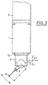
- the coordinate measuring machine shown in Figure 1 is from so-called portal type. Accordingly, it is there with (3) designated, bridge-shaped portal, which e.g. about air bearings with one foot on the measuring table (1) and with the other foot on the attached guide track (2) supports, in the direction of with (y) arrow motor-driven.
- the Cross slide (5) is designed as an x-guide Cross member (4) movably mounted.
- the one labeled (6) actual measuring arm, the so-called quill is in the cross slide (5) vertically (z) slidably guided and carries on Underside of a so-called “measuring" probe (7) on which the actual stylus (9) with its probe ball (19) over a passive swivel joint (8) is attached.
- the probe (7) can, for example, the one described in DE-OS 44 24 225.5, from three parallelogram guides built on each other formed probe.
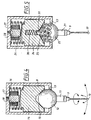
- the structure of the swivel joint (8) shows the in more detail Figure 4. It consists essentially of a ball joint, whereby the ball (12) on which a receptacle (11) for the stylus (9) attached, lies in an annular bearing pan (13). For Clamping the ball serves a cylindrical body (14) which in Housing (8) is guided straight and by a coil spring (16) is pressed in the direction of the annular bearing (13). He has on its underside a conical bore (15) which the spherical surface presses.
- the body (14) consists at least in upper part made of soft iron.
- the ball (12) is coaxial with the spring (16) Switching magnet used, which consists of a permanent magnet (18) and an electromagnet (17) placed around it. So lets the field of the permanent magnet due to a short current surge Reinforce (18) so that the part (14) to the Permanent magnet (18) is attracted where it sticks until it by a current pulse of opposite polarity is dropped again.
- the ball is in normal measuring operation of the coordinate measuring machine (12) of the rotary swivel joint (8) clamped so that the Workpiece on the probe ball (19) exerted measuring forces on the Transfer probe (7) ( Figure 1).
- the stylus is realigned.
- the coordinate measuring machine (12) of the rotary swivel joint (8) clamped so that the Workpiece on the probe ball (19) exerted measuring forces on the Transfer probe (7) ( Figure 1).
- the stylus is realigned.
- the coordinate measuring machine is as in Figure 1 and in the enlarged 2 shows a centering body (10) built up. It has the shape of a hedgehog or morning star on its spherical surface a variety of outward directed tips that are so close together that between the Pointed depressions are formed in which the probe ball (19) can feel self-centering.
- the ball (12) is passive Rotary swivel joint (8) unclamped. Then does that Coordinate measuring device by simultaneously controlling at least two Drive the center of the ball (12) on a circular path the center of the probe ball (19). This is in Figure 2 explained in more detail. There is (29) the point in the swivel joint (8) referred to by the stylus (9) rotated or can be pivoted. Its distance (a) from The center of the probe ball (19) is known and can determined, for example, by calibration on a test standard become.
- the above-described pivoting process of the button with the help the drives of the coordinate measuring machine can always be "in one Pull "as long as the swivel angle does not become too large and exceeds the opening angle of the centering gap in which is keyed in. It is to bring about greater swivel angles however, easily possible, the pivoting process in two stages or to design in several stages. This is done first in a centering gap keyed in and the stylus by a smaller angle pivoted. Then the stylus is removed from the Centering gap extended and then it becomes temporary Clamp the swivel joint (8) in another Centering gap keyed in, which then swivels the Styli allowed.
- the required centering gaps can be done in different ways will be realized.
- the tips of the centering body (10) can also, for example, as shown in FIG Surface of a larger ball (20) with balls (20a, 20b) smaller diameter can be glued, or it can be in the Conical holes are introduced into the spherical surface.
- the surface of the ball (22) the bearing of the joint with a variety of conical Provide holes and in the bottom of the for clamping serving part (24) is made a central bore, in which a locking ball (31) and a spring (30) are added.
- the spring (30) has compared to the spring (26) with which the part (24) is pressed against the ball (22) of the bearing, a very much lower spring constant. In this way unclamped state the ball (22) with the attached Stylus (9) snapping into discrete without great forces Angular positions are aligned before then subsequently this position is fixed. This is done by using the combined electromagnets (27) and permanent magnets (28) Part (24) released and from the spring (26) for clamping on the Surface of the ball (22) is pressed.
- a ball joint it is also not essential to have a ball joint to be used for the storage of the stylus.
- a universal joint can be used or a any other joint that has at least one, preferably but has two axes of rotation or swivel. These axes must do not necessarily intersect at one point. Because even if the axes are spaced, they can be any for on circular arcs, but with different ones Diameter, in relation to the center of the probe ball be moved. Can be used as storage for the stylus for example, that described in DE-OS 44 35 401 spherical bearings can be used.
- the joint also has to not necessarily be driven on circular paths, even if it is this is an advantageous embodiment variant. Any other lanes are of course also possible. Ultimately, the only thing that matters is that the joint does this is that the probe shaped body (19) centered in the device (10) remains.
Landscapes
- Physics & Mathematics (AREA)
- General Physics & Mathematics (AREA)
- A Measuring Device Byusing Mechanical Method (AREA)
- Length Measuring Devices With Unspecified Measuring Means (AREA)
Claims (15)
- Appareil de mesure de coordonnées avec un palpeur (9), dont l'orientation spatiale est réglable par voie mécanique, dans lequel le palpeur (9) ou la tête de palpeur (7), à laquelle il est fixé, est supporté(e) par une articulation de façon rotative, respectivement pivotante selon au moins un axe et il est prévu des moyens (14-18; 24-28) pour empêcher le mouvement pivotant ou pour bloquer l'articulation, caractérisé en ce que, sur la partie (1) de l'appareil de mesure de coordonnées, par rapport à laquelle le palpeur (9) est mobile, est fixé un équipement (10), sur lequel le corps de détection (19) du palpeur (9) peut être installé en position centrée, et en ce que la commande de l'appareil de mesure de coordonnées est configurée de telle manière qu'elle peut déplacer l'articulation pour le mouvement rotatif, respectivement pivotant, du palpeur (9) sur des trajectoires telles que le corps de détection (19) reste en position centrée dans l'équipement (10).
- Appareil de mesure de coordonnées suivant la revendication 1, caractérisé en ce que l'équipement pour l'installation centrée du corps de détection (19) est un corps convexe (10, 20) pourvu sur sa surface d'une pluralité de points de centrage.
- Appareil de mesure de coordonnées suivant la revendication 2, caractérisé en ce que le corps (10) est bâti à la manière d'un hérisson ou d'une étoile du matin.
- Appareil de mesure de coordonnées suivant la revendication 2, caractérisé en ce que les points de centrage sont formés par une pluralité de corps sphériques (20a, 20b) placés les uns à côté des autres.
- Appareil de mesure de coordonnées suivant la revendication 1, caractérisé en ce que le palpeur (9) est supporté de façon pivotante autour de deux axes perpendiculaires l'un à l'autre.
- Appareil de mesure de coordonnées suivant la revendication 1, caractérisé par une articulation avec un dispositif d'arrêt (27, 28) pour des positions angulaires discrètes du palpeur.
- Appareil de mesure de coordonnées suivant la revendication 5, dans lequel l'articulation est un palier sphérique (12, 15) ou un palier à cardan.
- Appareil de mesure de coordonnées suivant l'une quelconque des revendications 1 - 7, caractérisé par un équipement (17, 18) pour le blocage, respectivement le déblocage, mécanique de l'articulation.
- Appareil de mesure de coordonnées suivant la revendication 8, dans lequel l'équipement de blocage comprend un aimant permanent (18) et un électroaimant (17).
- Procédé pour l'alignement du palpeur (9) par voie mécanique dans un appareil de mesure de coordonnées, dans lequel le palpeur (9) ou la tête de palpeur (7), à laquelle il est fixé, est supporté(e) par une articulation de façon rotative, respectivement pivotante selon au moins un axe, caractérisé en ce quele palpeur (9) est amené avec son corps de détection (bille palpeuse 19) dans un logement de centrage (10),l'articulation est alors déplacée sur une trajectoire telle que le corps de détection (19) reste centré dans l'équipement (10) et que le palpeur (9) accomplisse ainsi un mouvement tournant, respectivement pivotant, etle palpeur (9), nouvellement orienté de cette manière, avec son corps de détection (19) est retiré du logement de centrage (10).
- Procédé suivant la revendication 10, dans lequel le calculateur ou la commande de l'appareil de mesure de coordonnées calcule, après l'entrée de la modification désirée de l'alignement du palpeur (9) en fonction de la distance actuelle entre le corps de détection (19) et l'articulation (29), la trajectoire circulaire sur laquelle l'articulation doit être déplacée, par un déplacement simultané de plusieurs chariots de mesure (3, 5, 6) de l'appareil de mesure de coordonnées, pour l'étape de l'alignement.
- Procédé suivant l'une des revendications 10 - 11, dans lequel, lorsque le palpeur (9) doit tourner, respectivement pivoter, d'une plus grande plage angulaire, plusieurs opérations individuelles de rotation, respectivement de pivotement, sont effectuées les unes après les autres et le logement de centrage (10a, b) est changé entre les opérations individuelles.
- Appareil de mesure de coordonnées avec un palpeur (9), dont l'orientation spatiale est réglable par voie mécanique dans lequel le palpeur (9) ou la tête de palpeur (7), à laquelle il est fixé, est supportée) de façon rotative, respectivement pivotante autour d'au moins un axe et il est prévu des moyens (14-18; 24-28) pour empêcher le mouvement pivotant ou pour bloquer l'axe (les axes), caractérisé en ce que, sur la partie (1) de l'appareil de mesure de coordonnées, par rapport à laquelle le palpeur (9) est mobile, est fixé un équipement (10), sur lequel le corps de détection (19) du palpeur (9) peut être installé en position centrée, et en ce que la commande de l'appareil de mesure de coordonnées est configurée de telle manière qu'elle peut déplacer les axes pour le mouvement tournant, respectivement pivotant, du palpeur (9) sur des trajectoires circulaires rapportées à la position du corps de détection (19) comme point central.
- Procédé pour l'alignement du palpeur (9) par voie mécanique, dans un appareil de mesure de coordonnées, dans lequel le palpeur (9) ou la tête de palpeur (7), à laquelle il est fixé, est supportée) de façon rotative, respectivement pivotante autour d'au moins un axe, caractérisé en ce quele palpeur (9) est amené avec son corps de détection (19) dans un logement de centrage (10),l'axe de rotation, respectivement de pivotement, est alors déplacé sur une trajectoire circulaire rapportée à la position du corps de détection centré (19) et que le palpeur (9) accomplisse ainsi un mouvement tournant, respectivement pivotant, tandis que le corps de détection (19) conserve sa position dans le logement de centrage (10), etle palpeur (9), nouvellement orienté de cette manière, avec son corps de détection (19) est ensuite retiré du logement de centrage (10).
- Procédé suivant la revendication 14, dans lequel le calculateur ou la commande de l'appareil de mesure de coordonnées calcule, après l'entrée de la modification désirée de l'alignement du palpeur (9) en fonction de la distance actuelle entre le corps de détection (19) et l'axe, respectivement les axes, (29), la trajectoire circulaire sur laquelle les axes doivent être déplacés, par un déplacement simultané de plusieurs chariots de mesure (3, 5, 6) de l'appareil de mesure de coordonnées, pour l'étape de l'alignement.
Applications Claiming Priority (2)
| Application Number | Priority Date | Filing Date | Title |
|---|---|---|---|
| DE19605776A DE19605776A1 (de) | 1996-02-16 | 1996-02-16 | Koordinatenmeßgerät mit einem Taststift, dessen Orientierung einstellbar ist |
| DE19605776 | 1996-02-16 |
Publications (3)
| Publication Number | Publication Date |
|---|---|
| EP0790478A2 EP0790478A2 (fr) | 1997-08-20 |
| EP0790478A3 EP0790478A3 (fr) | 1999-05-19 |
| EP0790478B1 true EP0790478B1 (fr) | 2001-12-19 |
Family
ID=7785589
Family Applications (1)
| Application Number | Title | Priority Date | Filing Date |
|---|---|---|---|
| EP97101083A Expired - Lifetime EP0790478B1 (fr) | 1996-02-16 | 1997-01-24 | Machine de mesure coordonnées avec palpeur orientable |
Country Status (3)
| Country | Link |
|---|---|
| US (1) | US5848477A (fr) |
| EP (1) | EP0790478B1 (fr) |
| DE (2) | DE19605776A1 (fr) |
Cited By (1)
| Publication number | Priority date | Publication date | Assignee | Title |
|---|---|---|---|---|
| EP4249847A2 (fr) | 2019-04-08 | 2023-09-27 | Carl Zeiss Industrielle Messtechnik GmbH | Procédé et dispositif informatique permettant de sélectionner une séquence de mesure pour un appareil de mesure de coordonnées |
Families Citing this family (37)
| Publication number | Priority date | Publication date | Assignee | Title |
|---|---|---|---|---|
| DE19712029A1 (de) * | 1997-03-21 | 1998-09-24 | Zeiss Carl Fa | Verfahren zur Steuerung von Koordinatenmeßgeräten nach Solldaten |
| US6598308B1 (en) * | 1997-11-28 | 2003-07-29 | Jne Ab | Measuring system |
| US5979070A (en) * | 1997-12-19 | 1999-11-09 | Lau; Kam C. | Method and apparatus for selectively locking a movement direction of a coordinate measurement probe |
| IT1299955B1 (it) | 1998-04-06 | 2000-04-04 | Marposs Spa | Testa per il controllo di dimensioni lineari di pezzi. |
| GB9813263D0 (en) * | 1998-06-20 | 1998-08-19 | Renishaw Plc | Touch probe |
| JP3633788B2 (ja) * | 1998-07-13 | 2005-03-30 | 株式会社ミツトヨ | 測定装置 |
| US6178654B1 (en) * | 1999-02-18 | 2001-01-30 | Ball Semiconductor, Inc. | Method and system for aligning spherical-shaped objects |
| DE29903815U1 (de) | 1999-02-22 | 1999-07-15 | Herz System- und Anlagentechnik GmbH, 29499 Zernien | Vorrichtung zur Steuerung des relativen Hubs eines an Objekten angreifenden Hubgeräts |
| US6536121B1 (en) * | 1999-08-06 | 2003-03-25 | Thk Co., Ltd. | Scribing apparatus |
| US6265234B1 (en) | 2000-01-25 | 2001-07-24 | Ball Semiconductor, Inc. | Alignment system for a spherical device |
| US6810600B1 (en) * | 2000-02-02 | 2004-11-02 | Unova Ip Corp. | Apparatus and method for monitoring alignment of a CNC machine spindle trunnion axis A |
| KR100441338B1 (ko) * | 2001-04-02 | 2004-07-23 | 헌 김 | 데이터 입력장치 |
| DE10122200A1 (de) * | 2001-05-08 | 2002-11-14 | Zeiss Carl | Tastkopf für ein Koordinatenmeßgerät. Koordinatenmeßgerät, Kalibrierkörper für ein Koordinatenmeßgerät und Verfahren zum Kalibrieren eines Koordinatenmeßgerätes |
| GB0114360D0 (en) * | 2001-06-13 | 2001-08-08 | Renishaw Plc | Stylus orientation |
| SE524543C2 (sv) * | 2002-01-17 | 2004-08-24 | Jne Ab | Mätlinjal, avsedd för symmetrimätningar på fordon |
| GB0215152D0 (en) * | 2002-07-01 | 2002-08-07 | Renishaw Plc | Probe or stylus orientation |
| DE10260670B4 (de) * | 2002-12-23 | 2007-04-05 | Carl Zeiss Industrielle Messtechnik Gmbh | Vorrichtung zum optischen Abtasten von Werkstücken |
| US20040207417A1 (en) * | 2003-04-16 | 2004-10-21 | Barr Andrew Harvey | Electronic probe with positionable tip |
| DE102005017708A1 (de) * | 2005-04-15 | 2006-10-19 | Wolfgang Madlener | Verfahren und Vorrichtung zum Vermessen von Werkstücken mit einem Messtaster an einer Werkzeugmaschine |
| SE531462C2 (sv) | 2005-11-17 | 2009-04-14 | Hexagon Metrology Ab | Inställningsanordning för ett mäthuvud |
| DE102005063242B4 (de) * | 2005-12-20 | 2011-01-13 | Carl Zeiss Industrielle Messtechnik Gmbh | Magnetkupplung, insbesondere zum Arretieren eines Drehgelenks bei einem Koordinatenmessgerät |
| JP5179760B2 (ja) * | 2007-02-05 | 2013-04-10 | 株式会社ミツトヨ | 座標測定用補助具、座標測定用プローブ及び座標測定機 |
| DE102007022326B4 (de) | 2007-05-08 | 2022-07-07 | Carl Zeiss Industrielle Messtechnik Gmbh | Koordinatenmessgerät zum Bestimmen von Raumkoordinaten an einem Messobjekt sowie Dreh-Schwenk-Mechanismus für ein solches Koordinatenmessgerät |
| US8024853B2 (en) * | 2007-12-19 | 2011-09-27 | Hitachi Global Storage Technologies, Netherlands B.V. | Head gimbal assembly (HGA) connector pad alignment jig |
| GB0804114D0 (en) * | 2008-03-05 | 2008-04-09 | Renishaw Plc | Surface sensing device |
| JP5269698B2 (ja) * | 2009-06-10 | 2013-08-21 | 株式会社ミツトヨ | 真円度測定装置 |
| DE102010006505B4 (de) | 2010-01-28 | 2013-09-19 | Carl Zeiss Industrielle Messtechnik Gmbh | Koordinatenmessgerät mit passivem Dreh-Schwenk-Mechanismus |
| GB201012249D0 (en) * | 2010-07-21 | 2010-09-08 | Renishaw Plc | Metrology apparatus |
| EP2614333B1 (fr) * | 2010-09-10 | 2021-08-11 | Carl Zeiss 3D Automation GmbH | Agencement de palpeur |
| GB2493214B (en) * | 2011-07-29 | 2016-06-08 | Taylor Hobson Ltd | Metrological apparatus |
| DE102012003321B4 (de) * | 2012-02-18 | 2015-07-23 | Federal-Mogul Burscheid Gmbh | Einrichtung zur Vermessung von Kolbenringen |
| EP3129750B1 (fr) | 2014-04-08 | 2023-05-31 | Nikon Metrology NV | Unité de sonde de mesure pour des applications métrologiques |
| JP6518421B2 (ja) * | 2014-09-24 | 2019-05-22 | 株式会社ミツトヨ | 真円度測定機およびその制御方法 |
| DE102015206308A1 (de) * | 2015-04-09 | 2016-10-13 | Carl Zeiss 3D Automation Gmbh | Taststifthalter |
| EP3184960B1 (fr) | 2015-12-22 | 2018-06-27 | Tesa Sa | Tête orientable motorisée pour système de mesure |
| DE102017114551B4 (de) | 2017-06-29 | 2021-12-23 | Carl Zeiss Industrielle Messtechnik Gmbh | Dreh-Schwenk-Mechanismus für ein Koordinatenmessgerät |
| DE102018115745B4 (de) | 2018-06-29 | 2024-12-05 | Carl Zeiss Industrielle Messtechnik Gmbh | Dreh-Schwenk-Mechanismus für ein Koordinatenmessgerät |
Family Cites Families (11)
| Publication number | Priority date | Publication date | Assignee | Title |
|---|---|---|---|---|
| GB1597842A (en) | 1977-02-07 | 1981-09-09 | Rolls Royce | Indexing mechanism |
| US4523450A (en) * | 1981-11-07 | 1985-06-18 | Carl-Zeiss-Stiftung, Heidenheim/Brenz | Method of calibrating probe pins on multicoordinate measurement machines |
| DE3434116C2 (de) | 1984-09-17 | 1986-11-20 | Fa. Carl Zeiss, 7920 Heidenheim | Elektromagnetische Bremse |
| DE3621626A1 (de) * | 1986-06-27 | 1988-01-14 | Zeiss Carl Fa | Halter fuer taststifte |
| GB2203837B (en) * | 1987-04-06 | 1991-02-20 | Mitutoyo Corp | Apparatus and method for spatial coordinate measurement |
| DE3740070A1 (de) | 1987-11-26 | 1989-06-08 | Zeiss Carl Fa | Dreh-schwenk-einrichtung fuer tastkoepfe von koordinatenmessgeraeten |
| GB8906287D0 (en) * | 1989-03-18 | 1989-05-04 | Renishaw Plc | Probe calibration |
| EP0392660B1 (fr) * | 1989-04-14 | 1993-09-08 | Renishaw plc | Tête de palpeur |
| US5251156A (en) * | 1990-08-25 | 1993-10-05 | Carl-Zeiss-Stiftung, Heidenheim/Brenz | Method and apparatus for non-contact measurement of object surfaces |
| CH687641A5 (de) | 1993-10-13 | 1997-01-15 | Max Oschwald | Sphorische Aufhaengung fuer ein technisches Instrument. |
| DE4424225A1 (de) * | 1994-07-09 | 1996-01-11 | Zeiss Carl Fa | Tastkopf für Koordinatenmeßgeräte |
-
1996
- 1996-02-16 DE DE19605776A patent/DE19605776A1/de not_active Withdrawn
-
1997
- 1997-01-24 EP EP97101083A patent/EP0790478B1/fr not_active Expired - Lifetime
- 1997-01-24 DE DE59705831T patent/DE59705831D1/de not_active Expired - Lifetime
- 1997-02-11 US US08/798,540 patent/US5848477A/en not_active Expired - Fee Related
Cited By (1)
| Publication number | Priority date | Publication date | Assignee | Title |
|---|---|---|---|---|
| EP4249847A2 (fr) | 2019-04-08 | 2023-09-27 | Carl Zeiss Industrielle Messtechnik GmbH | Procédé et dispositif informatique permettant de sélectionner une séquence de mesure pour un appareil de mesure de coordonnées |
Also Published As
| Publication number | Publication date |
|---|---|
| DE19605776A1 (de) | 1997-08-21 |
| EP0790478A2 (fr) | 1997-08-20 |
| DE59705831D1 (de) | 2002-01-31 |
| US5848477A (en) | 1998-12-15 |
| EP0790478A3 (fr) | 1999-05-19 |
Similar Documents
| Publication | Publication Date | Title |
|---|---|---|
| EP0790478B1 (fr) | Machine de mesure coordonnées avec palpeur orientable | |
| DE69207983T2 (de) | Kalibrier- und Messgerät | |
| EP0938641B1 (fr) | Procede et systeme de positionnement | |
| DE2804398B2 (de) | MeBkopf für KoordinatenmeBmaschinen | |
| EP2304387B1 (fr) | Dispositif de retenue pour retenir un élément d'étalonnage et procédé d'étalonnage d'un capteur de mesure d'un appareil de mesure de coordonnées | |
| EP0686829A2 (fr) | Appareil de mesure pour le contrÔle des dimensions de pièces cylindriques | |
| EP0332575B1 (fr) | Palpeur produisant une valeur de mesure en touchant une pièce à usiner | |
| EP1696289A1 (fr) | Procédé pour dimensionner une machine-outil | |
| DE3735075A1 (de) | Pruefeinrichtung und verfahren zur bestimmung der messunsicherheit von koordinatenmessgeraeten | |
| EP3569974B1 (fr) | Support de pièce, dispositif de mesure et procédé de mesure d'une pièce | |
| DE19604354A1 (de) | Verfahren zur koordinatenmäßigen Vermessung von Werkstücken auf Bearbeitungsmaschinen | |
| DE19708762B4 (de) | Verfahren zum Konfigurieren einer Vorrichtung für die Positionierung von Bauteilen auf einer Maschine | |
| DE102017105814B3 (de) | System zum Messen der Rauheit einer Oberfläche eines Werkstücks | |
| DE102019115630B3 (de) | Schwenktaster | |
| DE102017114551B4 (de) | Dreh-Schwenk-Mechanismus für ein Koordinatenmessgerät | |
| EP1187700B1 (fr) | Dispositif de positionnement pour porte-pieces ou pieces | |
| EP3314203A1 (fr) | Élément adapteur pour le montage d'un dispositif rotatif dans la chambre de mesure d'un appareil de mesure de coordonnées | |
| DE102019205145B4 (de) | Ausrichten von Komponenten relativ zu einem Koordinatenmessgerät | |
| DE102020114673B3 (de) | Sphärischer Parallelmanipulator, Schwenkeinrichtung und Messgerät | |
| DE3902854A1 (de) | Fertigungseinrichtung mit wechselpaletten | |
| WO2015014398A1 (fr) | Dispositif de retenue, ensemble contre-support et procédé de réglage d'un dispositif de retenue | |
| DE3422161C2 (fr) | ||
| DE10203002B4 (de) | Vorrichtung zum Kalibrieren eines Roboters | |
| DE102015211950B4 (de) | Adaptereinrichtung zur Montage eines Objekts auf dem Messtisch eines Koordinatenmessgeräts | |
| DE10319711A1 (de) | Verfahren zur hochgenauen dimensionalen Messung an Messobjekten |
Legal Events
| Date | Code | Title | Description |
|---|---|---|---|
| PUAI | Public reference made under article 153(3) epc to a published international application that has entered the european phase |
Free format text: ORIGINAL CODE: 0009012 |
|
| AK | Designated contracting states |
Kind code of ref document: A2 Designated state(s): DE FR GB IT |
|
| PUAL | Search report despatched |
Free format text: ORIGINAL CODE: 0009013 |
|
| AK | Designated contracting states |
Kind code of ref document: A3 Designated state(s): DE FR GB IT |
|
| 17P | Request for examination filed |
Effective date: 19991019 |
|
| GRAG | Despatch of communication of intention to grant |
Free format text: ORIGINAL CODE: EPIDOS AGRA |
|
| 17Q | First examination report despatched |
Effective date: 20010214 |
|
| RAP1 | Party data changed (applicant data changed or rights of an application transferred) |
Owner name: CARL-ZEISS-STIFTUNG, TRADING AS CARL ZEISS Owner name: CARL ZEISS |
|
| GRAG | Despatch of communication of intention to grant |
Free format text: ORIGINAL CODE: EPIDOS AGRA |
|
| GRAH | Despatch of communication of intention to grant a patent |
Free format text: ORIGINAL CODE: EPIDOS IGRA |
|
| GRAH | Despatch of communication of intention to grant a patent |
Free format text: ORIGINAL CODE: EPIDOS IGRA |
|
| GRAA | (expected) grant |
Free format text: ORIGINAL CODE: 0009210 |
|
| AK | Designated contracting states |
Kind code of ref document: B1 Designated state(s): DE FR GB IT |
|
| REG | Reference to a national code |
Ref country code: GB Ref legal event code: IF02 |
|
| REF | Corresponds to: |
Ref document number: 59705831 Country of ref document: DE Date of ref document: 20020131 |
|
| GBT | Gb: translation of ep patent filed (gb section 77(6)(a)/1977) |
Effective date: 20020311 |
|
| PLBE | No opposition filed within time limit |
Free format text: ORIGINAL CODE: 0009261 |
|
| STAA | Information on the status of an ep patent application or granted ep patent |
Free format text: STATUS: NO OPPOSITION FILED WITHIN TIME LIMIT |
|
| 26N | No opposition filed | ||
| REG | Reference to a national code |
Ref country code: GB Ref legal event code: 732E |
|
| PGFP | Annual fee paid to national office [announced via postgrant information from national office to epo] |
Ref country code: IT Payment date: 20090128 Year of fee payment: 13 |
|
| PGFP | Annual fee paid to national office [announced via postgrant information from national office to epo] |
Ref country code: FR Payment date: 20090115 Year of fee payment: 13 |
|
| REG | Reference to a national code |
Ref country code: FR Ref legal event code: ST Effective date: 20100930 |
|
| PG25 | Lapsed in a contracting state [announced via postgrant information from national office to epo] |
Ref country code: FR Free format text: LAPSE BECAUSE OF NON-PAYMENT OF DUE FEES Effective date: 20100201 |
|
| PG25 | Lapsed in a contracting state [announced via postgrant information from national office to epo] |
Ref country code: IT Free format text: LAPSE BECAUSE OF NON-PAYMENT OF DUE FEES Effective date: 20100124 |
|
| PGFP | Annual fee paid to national office [announced via postgrant information from national office to epo] |
Ref country code: DE Payment date: 20140122 Year of fee payment: 18 |
|
| PGFP | Annual fee paid to national office [announced via postgrant information from national office to epo] |
Ref country code: GB Payment date: 20140121 Year of fee payment: 18 |
|
| REG | Reference to a national code |
Ref country code: DE Ref legal event code: R119 Ref document number: 59705831 Country of ref document: DE |
|
| GBPC | Gb: european patent ceased through non-payment of renewal fee |
Effective date: 20150124 |
|
| PG25 | Lapsed in a contracting state [announced via postgrant information from national office to epo] |
Ref country code: DE Free format text: LAPSE BECAUSE OF NON-PAYMENT OF DUE FEES Effective date: 20150801 Ref country code: GB Free format text: LAPSE BECAUSE OF NON-PAYMENT OF DUE FEES Effective date: 20150124 |