EP0790675A2 - Unterbrechungsvorrichtung - Google Patents
Unterbrechungsvorrichtung Download PDFInfo
- Publication number
- EP0790675A2 EP0790675A2 EP97102439A EP97102439A EP0790675A2 EP 0790675 A2 EP0790675 A2 EP 0790675A2 EP 97102439 A EP97102439 A EP 97102439A EP 97102439 A EP97102439 A EP 97102439A EP 0790675 A2 EP0790675 A2 EP 0790675A2
- Authority
- EP
- European Patent Office
- Prior art keywords
- handle
- movable electrode
- lever
- fixed electrodes
- portions
- Prior art date
- Legal status (The legal status is an assumption and is not a legal conclusion. Google has not performed a legal analysis and makes no representation as to the accuracy of the status listed.)
- Withdrawn
Links
Images


Classifications
-
- H—ELECTRICITY
- H01—ELECTRIC ELEMENTS
- H01H—ELECTRIC SWITCHES; RELAYS; SELECTORS; EMERGENCY PROTECTIVE DEVICES
- H01H9/00—Details of switching devices, not covered by groups H01H1/00 - H01H7/00
- H01H9/08—Arrangements to facilitate replacement of a switch, e.g. cartridge housing
- H01H9/085—Arrangements to facilitate replacement of a switch, e.g. cartridge housing contact separation effected by removing contact carrying element
-
- H—ELECTRICITY
- H01—ELECTRIC ELEMENTS
- H01H—ELECTRIC SWITCHES; RELAYS; SELECTORS; EMERGENCY PROTECTIVE DEVICES
- H01H3/00—Mechanisms for operating contacts
- H01H3/02—Operating parts, i.e. for operating driving mechanism by a mechanical force external to the switch
-
- H—ELECTRICITY
- H01—ELECTRIC ELEMENTS
- H01R—ELECTRICALLY-CONDUCTIVE CONNECTIONS; STRUCTURAL ASSOCIATIONS OF A PLURALITY OF MUTUALLY-INSULATED ELECTRICAL CONNECTING ELEMENTS; COUPLING DEVICES; CURRENT COLLECTORS
- H01R13/00—Details of coupling devices of the kinds covered by groups H01R12/70 or H01R24/00 - H01R33/00
- H01R13/62—Means for facilitating engagement or disengagement of coupling parts or for holding them in engagement
- H01R13/629—Additional means for facilitating engagement or disengagement of coupling parts, e.g. aligning or guiding means, levers, gas pressure electrical locking indicators, manufacturing tolerances
- H01R13/633—Additional means for facilitating engagement or disengagement of coupling parts, e.g. aligning or guiding means, levers, gas pressure electrical locking indicators, manufacturing tolerances for disengagement only
- H01R13/6335—Additional means for facilitating engagement or disengagement of coupling parts, e.g. aligning or guiding means, levers, gas pressure electrical locking indicators, manufacturing tolerances for disengagement only comprising a handle
-
- H—ELECTRICITY
- H01—ELECTRIC ELEMENTS
- H01H—ELECTRIC SWITCHES; RELAYS; SELECTORS; EMERGENCY PROTECTIVE DEVICES
- H01H1/00—Contacts
- H01H1/12—Contacts characterised by the manner in which co-operating contacts engage
- H01H1/36—Contacts characterised by the manner in which co-operating contacts engage by sliding
- H01H1/38—Plug-and-socket contacts
-
- H—ELECTRICITY
- H01—ELECTRIC ELEMENTS
- H01H—ELECTRIC SWITCHES; RELAYS; SELECTORS; EMERGENCY PROTECTIVE DEVICES
- H01H9/00—Details of switching devices, not covered by groups H01H1/00 - H01H7/00
- H01H9/10—Adaptation for built-in fuses
- H01H2009/108—Building a sliding and/or a removable bridging connector for batteries
-
- H—ELECTRICITY
- H01—ELECTRIC ELEMENTS
- H01H—ELECTRIC SWITCHES; RELAYS; SELECTORS; EMERGENCY PROTECTIVE DEVICES
- H01H9/00—Details of switching devices, not covered by groups H01H1/00 - H01H7/00
- H01H9/0066—Auxiliary contact devices
-
- H—ELECTRICITY
- H01—ELECTRIC ELEMENTS
- H01H—ELECTRIC SWITCHES; RELAYS; SELECTORS; EMERGENCY PROTECTIVE DEVICES
- H01H9/00—Details of switching devices, not covered by groups H01H1/00 - H01H7/00
- H01H9/10—Adaptation for built-in fuses
Definitions
- the present invention relates to a breaker device disposed or disposable in a power supply circuit of, e.g. an electric automotive vehicle.
- a known breaker device of this type is of so-called knife switch type in which a lever type movable electrode is rotatably supported on one of a pair of fixed electrodes spaced on a base plate, and a current is interrupted by inclining the movable electrode from its standing position to be inserted into an elastically holding portion formed at the other fixed electrode.
- the fixed electrodes may be electrically connected by engaging a pair of movable electrodes therewith and may be disconnected by disengaging the movable electrodes therefrom.
- a handle is provided at the pair of movable electrodes to be gripped, operability in engaging and disengaging the movable electrodes with and from the fixed electrodes can be improved.
- the breaker device is required to have a small size so that it will take up only a small space when being mounted on a vehicle body. In order to meet this requirement, the handle may be made inclinable. The handle is held in its standing position at the time of the engagement and disengagement of the movable electrodes, and is held in its resting position upon completion of the engagement or disengagement.
- the breaker device according to the invention was developed in view of the above problem, and an object thereof is to prevent an insufficient engagement of electrodes.
- a breaker device comprising:
- each lever functioning portion comprises a receiving portion, preferably provided at the casing, and an engaging portion, preferably provided at the handle, at a side opposite from an operable portion of the handle with respect to a rotation center shaft, and preferably a rotating force applied to the operable portion is translated into an engaging force applied to the movable electrode via the rotation center shaft by the action of lever with a position where the receiving portion and the engaging portion are engaged as a fulcrum.
- the engaging portions engage the receiving portions during the rotation of the handle.
- the lever action works with the engagement positions of the engaging portions and the receiving portions as a fulcrum, and the rotating force applied to the operable portion acts on the movable electrode via the rotation center shaft. As a result, the movable electrode is displaced to the proper engagement position.
- the casing and the handle are provided with a rotation restricting means for restricting the rotation of the handle, in particular by the contact of a restricting portion and a slidable element while the handle is operated, preferably at least until the movable electrode reaches a proper engagement position.
- the handle 40 While the handle is used for the engagement of the electrodes, the rotation thereof is restricted by the contact of the slidable element and the restricting portion. Thus, even if a fitting resistance increases at the start of or during the engagement, the handle 40 does not wobble, i.e. the engagement can be performed with an improved operability.
- the slidable element is provided with one or more bevelled portions for facilitating the lever action or the rotation or pivotal movement of the handle or allowing for an earlier rotation of the handle, i.e. when the movable electrode is less engaged with the fixed electrodes.
- the lever functioning portions provide the action of lever, when the movable electrode is in a position substantially close or neighboring to its proper engagement position, preferably when sealing means and sealing portions provided in connection with the movable electrode and the fixed electrodes come substantially into contact with each other.
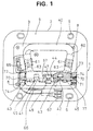
- a casing 1 made of e.g. synthetic resin includes upper and lower casings 2 and 3.
- the lower casing 2 is in the form of a bottomed tube having a substantially rectangular cross section, and its bottom wall 4 is located substantially in the middle of its height.
- a mount flange 5 is formed around the outer surface of the bottom end of the lower casing 2. This flange 5 is mounted on an unillustrated vehicle body by fastening screws through mount holes 6 formed in its four corners.
- the upper casing 3 is formed into a lid-like shape to be fitted to the upper end of the lower casing 2.
- the upper casing 3 is detachably fitted to the lower casing 2 by fastening screws 8 inserted through insertion holes formed in four corners of its upper surface into screw holes formed in four corners of the upper end surface of the lower casing 2.
- a pair of fixed electrodes 11a, 11b are placed substantially upright at one side (lower right side in FIG. 4), and a fuse 12 is accommodated at the other side.
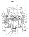
- a pair of internally threaded members 13 are buried in the bottom wall 4 at a specified interval e.g. by insert molding as shown in FIG. 2.
- Each of the fixed electrodes 11a, 11b is preferably in the form of a pin, and formed with a hexagonal portion 15 in its longitudinal center and with an externally threaded portion 16 at its bottom end.
- the respective electrodes 11a, 11b can stand by spirally fitting the externally threaded portions 16 with the corresponding internally threaded members 13.
- a terminal fitting 18 connected with one cut end of a wire a is secured to one fixed electrode 11a (left one in FIG. 2). This part of the wire a is drawn out through a first insertion hole 19 formed in the bottom wall 4. Further, a busbar 20 connected with one end of the fuse 12 to be described later is secured to the other fixed electrode 11b.
- connection members 23, 24 project from the opposite ends of the fuse 12.
- One connection member 23 is secured to a terminal fitting 26 connected with the other cut end of the wire a by fastening a bolt 27.
- This part of the wire a is drawn through a second insertion hole (not shown) similar to the above insertion hole 19 formed in the bottom wall 4.
- Waterproof plugs 29 mounted on the wire a are fitted into the insertion holes 19, 28 to seal the openings.
- To the other connection member 24 of the fuse 12 is secured one end of the substantially horizontally extending busbar 20 by another bolt 27.
- the other end of the busbar 20 is secured to the fixed electrode 11b as described above.
- a movable electrode 31 is detachably engageable with or insertable or fittable on the pair of fixed electrodes 11a, 11b. As shown in FIG. 2, the movable electrode 31 is constructed such that a bridging member 33 is bridged between a pair of louver terminals 32a, 32b engageable with or fittable on the leading ends of the respective fixed electrodes 11a, 11b so as to connect the louver terminals 32a, 32b.
- the movable electrode 31 is formed by mounting the respective louver terminals 32a, 32b on a narrow mount body 35 e.g. of synthetic resin such by insert molding that the terminals 32a, 32b project from the bottom surface of the mount body 35. O-rings 37 are fitted on the outer surfaces of the louver terminals 32a, 3b of the movable electrode 31.
- a pair of insertion holes 36 into which the louver terminals 32a, 32b of the movable electrode 31 are insertable are formed in positions of the ceiling wall of the upper casing 3 corresponding to or right above the fixed electrodes 11a, 11b.
- Tubular portions 36A are formed at the edges of the insertion holes 36 so as to extend inward of the lower casing 2.
- the O-rings 37 of the louver terminals 32a, 32b come into close contact with the inner surfaces of the tubular portions 36A, thereby ensuring watertightness between the louver terminals 32a, 32b and the insertion holes 36.
- louver terminals 32a, 32b are inserted into the insertion holes 36 to be engaged with the pair of fixed electrodes 11a, 11b within the casing 1, or withdrawn from the insertion holes 36 to be disengaged from the fixed electrodes 11a, 11b.
- a breaker switch 38 for connecting and disconnecting the fixed electrodes 11a, 11b.
- the fuse 12 is disposed in an intermediate position of the wire a while being connected in series with the breaker switch 38.
- a handle 40 used to engage and disengage the movable electrode 31 is provided at the upper surface of the mount body 35.
- the handle 40 is preferably in the form of a frame having an outer shape of substantially an inverted trapezoid.
- Bearing portions 41 formed with bearing holes 42 project at the opposite ends of the upper surface of the mount body 35 with respect to its longitudinal direction.
- a pair of bearing portions 43 forked to hold the bearing portions 41 and formed with bearing holes 44 project at the edge of the mount side of the handle 40.
- the bearing portions 41 of the mount body 35 are fitted or inserted into recesses of the corresponding forked bearing portion 43 of the handle 40.
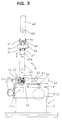
- the handle 40 can be held, by toggle action, in a standing position where it stands substantially upright at the opposite side of the louver terminals 32a, 32b (see phantom line position of FIG. 3) and in a resting position where it substantially lies in a direction at an angle different from 0° or 180°, in particular substantially normal to the projection direction of the louver terminals 32a, 32b.
- a spring member 47 as shown in FIG. 5 is mounted between the mount body 35 and the handle 40.
- a projected portion 48 is formed substantially in the longitudinal center of the upper surface of the mount body 35, and a mount projection 49 in the form of a narrow substantially rectangular column extending in a direction at an angle different from 0° or 180°, in particular substantially normal to the longitudinal direction of the mount body 35 projects from the top surface of the projected portion 48.
- Hooks 50 project from the opposite longer sides of the upper end of the mount projection 49.
- the spring member 47 is made by pressing a spring steel plate, and formed such that bent portions 53 inwardly bent to have a specified shape are symmetrically formed at the opposite ends of a strip-like base plate 52.
- a substantially rectangular engaging hole 54 fittable to the mount projection 49, and a pair of engaging portions 55 are formed by bending at the opposite longer ends of the engaging hole 54.
- the spring member 47 is disengageably and unrotatably mounted by fitting the engaging hole 54 with the mount projection 49 while arranging the base plate 52 and the mount body 35 such that they extend in directions at an angle different from 0° or 180°, in particular in substantially orthogonal directions until the base plate 52 is pressed against the projected portion 48 as shown by phantom line in FIG. 5, and by engaging the leading ends of the engaging portions 55 with the hooks 50 of the mount projection 49.
- a recess 57 for accommodating the spring member 47 mounted on the mount body 35.
- the bottom surface of the recess 57 acts as a contact surface 58 with which the bent portions 53 of the spring member 47 come into contact.
- the handle 40 is pivotal about the support shafts 45 by bringing the bent portion 53 of the spring member 47 into contact with the contact surface 58 and causing it to elastically and/or plastically contract.
- the handle 40 upon being subject to a kind of toggle action, the handle 40 can stably be held in the operative position where it extends in a direction opposite from the projecting direction of the louver terminals 32a, 32b while the contact surface 58 is held in contact with the bent portions 53 to their leading ends and in the resting position where it extends in a direction at an angle different from 0° or 180°, in particular substantially normal to the projecting direction of the louver terminals 32a, 32b while the contact surface 58 is completely held in contact with the side surface of either one of the bent portions 53.
- support tables 60 are provided as shown in FIGS. 1 and 3.
- a substantially L-shaped receiving member 61 is mounted on each support table 60.
- the receiving members 61 receive the substantially center portions of the opposite side portions of the handle 40 when the movable electrode 31 is properly engaged with the fixed electrodes 11a, 11b and the handle 40 is inclined to its resting position.
- Magnets 63 are mounted preferably in symmetrical positions of the outer surfaces of the opposite side portions of the hand 40.
- a lead switch 65 is mounted on the ceiling surface of the upper casing 3.
- the lead switch 65 is so disposed as to be located right before one of the magnets 63 when the movable electrode 31 is properly engaged with the fixed electrodes 11a, 11b and the handle 40 is inclined to its resisting position as described above, and outputs a detection signal when the magnet 63 comes right before it.
- the lead switch 65 is connected with an unillustrated control unit for performing necessary controls via a connector 67 mounted by a bracket 66 at one side surface of the upper casing 3.
- a rotation restricting means for guiding the movable electrode 31 to the position for the engagement with the fixed electrodes 11a, 11b and a lever functioning portion for preventing the movable electrode 31 from being held insufficiently engaged with the fixed electrodes 11a, 11b.
- slidable projections (slidable element according to the invention) 70 in the form of rectangular columns are integrally formed to project toward the opposite ends of the rotation center shafts 45.
- an insertion hole 71 for the corresponding shaft 45 is substantially coaxially formed with the bearing hole 44.
- the bearing hole 44 and the insertion hole 71 are located in a position displaced upward from the center position of the slidable projection 70 as shown in FIG. 6.
- the slidable projection 70 projects toward a side opposite from an operable portion 40A of the handle 40, i.e. toward the movable electrode 31 shown in FIG. 6.
- the projecting end of the slidable projection 70 acts as an engaging portion 77 which displays a lever action as described later.
- a guide wall 73 stands at each of left and right sides of the upper surface of the upper casing 3 where the handle 40 is inserted.
- Each guide wall 73 is formed with a restricting slot 74 (restricting portion according to the invention) for guiding the slidable projection 70 while the handle 40 is inserted.
- the restricting slot 74 is open in a direction of insertion of the movable electrode 31, in particular substantially upward and extends along the vertical direction as shown in FIG. 6.
- the slidable projection 70 is fitted or inserted into the restricting slot 74 such that it can freely make only a sliding movement.
- the restricting slot 74 and the slidable projection 70 construct a rotation restricting means according to the invention.
- a largely cut out rotation permitting portion 76 is formed continuously with and below or after the restricting slot 74 (as seen in a direction of insertion).
- a surface of the rotation permitting portion 76 at the right side of FIGS. 6 to 7 acts as a small arcuate surface 76A for avoiding the interference with a portion of the slidable projection 70 close to the rotation center shaft 45.
- a surface of the rotation permitting portion 76 opposite from the small arcuate surface 76A acts as a large arcuate portion 76B for avoiding the interference with the engaging portion 77 at the leading end of the slidable projection 70.
- a portion connecting the large arcuate portion 76B and the restricting slot 74 acts as a receiving portion 75 engageable with the corresponding engaging portion 77.
- the receiving portion 75 and the engaging portion 77 construct a lever functioning portion according to the invention. If the handle 40 is rotated from the operative position to the resting position in a state where the movable electrode 31 is insufficiently engaged with the fixed electrodes 11a, 11b, i.e. the rotation center shafts 45 are located above their positions attainable at the time of the proper engagement of the electrodes, the engaging portions 77 substantially come into contact with the receiving portions 75 from below (or in a direction against insertion).
- a lever action works with the engagement positions of the engaging portions 77 and the receiving portions 75 as a fulcrum.
- a rotating force applied to the operable portion 40A acts on the movable electrode 31 in an engaging direction via the rotation center shafts 45 and the mount body 35. Further, the engaging force which acts on the movable electrode 31 at this time is larger than the force applied to the operable portion 40A.
- the pair of fixed electrodes 11a, 11b stand and the fuse 12 is accommodated in the casing 1, and the fixed electrodes 11a, 11b and the fuse 12 are connected between the cut ends of the wire a as described above.
- the handle 40 is raised to its operative position outside the casing 1. Then, the handle 40 is held in the operative position by the aforementioned toggle action of the spring member 47.
- the louver terminals 32a, 32b of the movable electrode 31 projecting from the mount body 35 are inserted into the insertion holes 36 formed in the upper casing 3 by gripping the operable portion 40A of the handle 40.
- the handle 40 since the handle 40 is held onto the mount body 35, the mount body 35 or the movable electrode 31 does not wobble, with the result that the louver terminals 32a, 32b can smoothly be inserted into the insertion holes 36.
- the louver terminals 32a, 32b of the movable electrode 31 are so positioned as to be fittable to or insertable on the fixed electrodes 11a, 11b, in particular by fitting the slidable projections 70 into the restricting slots 74.
- the movable electrode 31 can easily and securely be fitted to the fixed electrodes 11a, 11b and be inserted into the insertion holes 36.
- the rotation of the handle 40 is restricted by fitting the slidable projections 70 into the restricting slots 74. Accordingly, even if a fitting resistance acts at the start of the engagement of the louver terminals 32a, 32b with the fixed electrodes 11a, 11b, the handle 40 does not wobble, i.e. the engagement can be performed with an improved operability.
- a fitting resistance acts between the electrodes upon the start of the engagement of the louver terminals 32a, 32b with the corresponding fixed electrodes 11a, 11b.
- the handle 40 since the louver terminals 32a, 32b are guided by the tubular portions 36A extending downward from the insertion holes 36, the handle 40 does not wobble. Further, the wobble of the handle 40 with respect to the louver terminals 32a, 32b is prevented by the holding force of the spring member 47 as well as by the fitting of the slidable projections 70 into the restricting slots 74. Thus, the handle 40 is pressed straight while being held in a fixed position without rotating, and the louver terminals 32a, 32b are smoothly engaged with the fixed electrodes 11a, 11b.
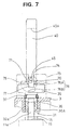
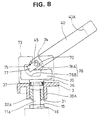
- the O-rings 37 come into contact with the edges of the insertion holes 36 as shown in FIG. 7. If the handle 40 is further pressed in this state, the movable electrode 31 is properly engaged with the fixed electrodes 11a, 11b. Thereby, the breaker switch 38 is turned on, and the wire a is brought into a conductive or usable state via the fuse 12.
- one of the magnets 63 provided at the handle 40 is located immediate before the lead switch 65, which in turn sends a detection signal. As a result, it can electrically be detected that the breaker switch 38 is properly turned on.
- the handle 40 Since the handle 40 is also held in the resting position by the toggle action of the spring member 47, it does not wobble even upon being subjected to vibrations while a vehicle is driving.
- the O-rings 37 are pressed into the insertion holes 36 while undergoing an elastic deformation, with the result that the fitting resistance suddenly becomes larger. This may cause an undesirable situation where an operator misjudges that the proper engagement has been attained despite the fact that the electrodes are still insufficiently engaged, stops the engaging operation, and moves onto an operation of rotating the handle 40 to the resting position.
- the movable electrode 31 can properly be engaged with the fixed electrodes 11a, 11b even in such a case.
- louver terminals 32a, 32b can easily be inserted into the insertion holes 36 against the elastic forces of the O-rings 37 and engaged with the fixed electrodes 11a, 11b (see FIG. 8).
- the movable electrode 31 reaches a proper engagement position when the handle 40 is inclined to the resting position.
- the handle 40 When the breaker switch 38 is turned off for the maintenance, the handle 40 is raised to the standing position from the resting position indicated by solid line in FIG. 3. The handle 40 is then pulled up to withdraw the movable electrode 31 from the fixed electrodes 11a, 11b, with the result that the breaker switch 38 is turned off, bringing the wire a into a nonconductive state.
- the breaker switch 38 is turned off by withdrawing the movable electrode 31 in the similar manner as above, and the screws 8 are loosened to remove the upper casing 3. Since the fuse 12 is exposed in this state, the fuse 12 is removed by loosening the bolts 27 and replaced with a new one. Because the breaker switch 38 is already turned off, the fuse 12 can be safely exchanged.
- the breaker device of this embodiment is excellent in safety because of its construction in which the conductive path is located inside the casing 1 and is allowed to have a compact configuration of particularly low height while being in use because the handle 40 can be inclined to the resting position.
- the movable electrode 31 can be brought into a properly engaged state by the action of lever. The prevents the movable electrode 31 from being held insufficiently engaged.
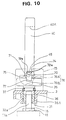
- FIG. 10 shows a further preferred embodiment of the invention, in which the slidable element 70 is formed with one or more bevelled portions 70a, such that a rotation or pivotal movement of the handle 40 can be performed earlier, i.e. when the movable electrode 31 is less engaged with the fixed electrodes 11a, 11b.
- the bevelled portions 70a prevent the slidable element 70 to interact with the linear portion 74 in such a position, when the slidable element 70 is already substantially arranged in the rotation permitting portion 76, therefore allowing for an earlier lever action by the lever functioning portion 75, 76.
Landscapes
- Arc-Extinguishing Devices That Are Switches (AREA)
- Switch Cases, Indication, And Locking (AREA)
- Breakers (AREA)
Applications Claiming Priority (15)
| Application Number | Priority Date | Filing Date | Title |
|---|---|---|---|
| JP2780196 | 1996-02-15 | ||
| JP27801/96 | 1996-02-15 | ||
| JP02780196A JP3444388B2 (ja) | 1996-02-15 | 1996-02-15 | ブレーカ装置 |
| JP07713396A JP3435973B2 (ja) | 1996-03-29 | 1996-03-29 | ブレーカ装置 |
| JP77133/96 | 1996-03-29 | ||
| JP7713396 | 1996-03-29 | ||
| JP9573696 | 1996-04-17 | ||
| JP95736/96 | 1996-04-17 | ||
| JP9573696A JPH09282980A (ja) | 1996-04-17 | 1996-04-17 | ブレーカ装置 |
| JP303358/96 | 1996-11-14 | ||
| JP30335896 | 1996-11-14 | ||
| JP30335896A JP3360713B2 (ja) | 1996-11-14 | 1996-11-14 | ブレーカ装置 |
| JP30525996 | 1996-11-15 | ||
| JP305259/96 | 1996-11-15 | ||
| JP30525996A JP3389796B2 (ja) | 1996-11-15 | 1996-11-15 | ブレーカ装置 |
Publications (2)
| Publication Number | Publication Date |
|---|---|
| EP0790675A2 true EP0790675A2 (de) | 1997-08-20 |
| EP0790675A3 EP0790675A3 (de) | 1999-09-22 |
Family
ID=27520970
Family Applications (1)
| Application Number | Title | Priority Date | Filing Date |
|---|---|---|---|
| EP97102439A Withdrawn EP0790675A3 (de) | 1996-02-15 | 1997-02-14 | Unterbrechungsvorrichtung |
Country Status (3)
| Country | Link |
|---|---|
| US (1) | US5842560A (de) |
| EP (1) | EP0790675A3 (de) |
| CN (1) | CN1047019C (de) |
Cited By (2)
| Publication number | Priority date | Publication date | Assignee | Title |
|---|---|---|---|---|
| EP1117112A3 (de) * | 2000-01-14 | 2002-03-20 | Autonetworks Technologies, Ltd. | Trennschalter |
| US6456187B2 (en) | 1999-08-18 | 2002-09-24 | Autonetworks Technologies, Ltd. | Breaker apparatus |
Families Citing this family (21)
| Publication number | Priority date | Publication date | Assignee | Title |
|---|---|---|---|---|
| JP3678600B2 (ja) | 1999-03-11 | 2005-08-03 | 株式会社オートネットワーク技術研究所 | ブレーカ装置 |
| US6407656B1 (en) | 1999-08-18 | 2002-06-18 | Autonetworks Technologies, Ltd. | Breaker device |
| US6949712B1 (en) * | 1999-10-12 | 2005-09-27 | Honeywell International Inc. | Actuator |
| JP3798938B2 (ja) | 2000-12-01 | 2006-07-19 | 株式会社オートネットワーク技術研究所 | ブレーカ装置 |
| JP3753943B2 (ja) | 2001-01-23 | 2006-03-08 | 株式会社オートネットワーク技術研究所 | ブレーカ装置 |
| US6791039B1 (en) * | 2002-09-30 | 2004-09-14 | Robert M. Tuniewicz | Multi-terminal electrical safety switch for simultaneously closing and opening electrical circuits connected thereto |
| JP2008004295A (ja) * | 2006-06-20 | 2008-01-10 | Toshiba Corp | シガライターソケットに挿抜可能なプラグ、およびプラグ付きコード |
| DE102007023234A1 (de) * | 2007-05-18 | 2008-11-20 | Kostal Kontakt Systeme Gmbh | Leistungstrennschalter für ein Kraftfahrzeug |
| DE102007023273A1 (de) * | 2007-05-18 | 2008-11-20 | Kostal Kontakt Systeme Gmbh | Leistungstrennschalter für ein Kraftfahrzeug |
| EP2112675B1 (de) * | 2008-04-01 | 2014-11-12 | Wöhner GmbH & Co. KG Elektrotechnische Systeme | Lasttrennschalter |
| US7893809B2 (en) * | 2009-02-19 | 2011-02-22 | Tyco Electronics Corporation | Service disconnect assembly for a high voltage electronic module |
| DE102009017338B4 (de) * | 2009-04-14 | 2016-12-01 | Wöhner GmbH & Co. KG Elektrotechnische Systeme | Halter für Sicherungen |
| US8098126B2 (en) * | 2009-04-22 | 2012-01-17 | Lg Chem, Ltd. | High voltage service disconnect assembly |
| GB2469855B (en) * | 2009-04-30 | 2013-05-22 | Harwin Plc | Locking apparatus for electrical connectors |
| MY161783A (en) | 2010-11-23 | 2017-05-15 | Nissan Motor | Power circuit interrupting device |
| US9214310B2 (en) * | 2012-10-29 | 2015-12-15 | Tyco Electronics Corporation | Service disconnect assembly |
| US9297860B2 (en) | 2012-12-03 | 2016-03-29 | Lg Chem, Ltd. | High voltage service disconnect assembly and method for determining an isolation resistance fault of a battery pack |
| US9251985B2 (en) | 2013-08-08 | 2016-02-02 | Lg Chem, Ltd. | Fuse lock-out assembly for a battery pack |
| US9231359B1 (en) * | 2014-08-15 | 2016-01-05 | Lear Corporation | Manual service disconnect for an electric circuit |
| US9613776B2 (en) | 2014-08-19 | 2017-04-04 | Regal Beloit America, Inc. | Fuse holder and associated method |
| CN107154643B (zh) * | 2017-05-18 | 2023-06-23 | 平顶山市津电智能科技有限公司 | 一种变压器组自调控系统 |
Family Cites Families (10)
| Publication number | Priority date | Publication date | Assignee | Title |
|---|---|---|---|---|
| US3183335A (en) * | 1962-03-23 | 1965-05-11 | Albert & J M Anderson Mfg Co | High pressure contact switch with rotatable locking means |
| US4026623A (en) * | 1976-03-08 | 1977-05-31 | International Telephone And Telegraph Corporation | Zero force connector |
| US4186288A (en) * | 1978-09-01 | 1980-01-29 | Stackpole Components Company | Slide switch |
| JPS5827400A (ja) * | 1981-08-11 | 1983-02-18 | 山一電機工業株式会社 | Icソケツトにおけるic押さえ板のロツク機構 |
| CN2114215U (zh) * | 1992-02-27 | 1992-08-26 | 昆山市陈墓镇广播电视站 | 旋转手柄离合装置 |
| FR2696866B1 (fr) * | 1992-10-13 | 1994-12-02 | Merlin Gerin | Mécanisme d'actionnement d'un interrupteur à trois positions. |
| JP2909525B2 (ja) * | 1993-04-19 | 1999-06-23 | 矢崎総業株式会社 | コネクタ装置 |
| JPH06327123A (ja) * | 1993-05-08 | 1994-11-25 | Sumitomo Wiring Syst Ltd | ジャンクションボックス |
| US5562490A (en) * | 1993-12-27 | 1996-10-08 | General Motors Corporation | High ampacity electrical quick disconnect |
| DE29513997U1 (de) * | 1995-08-31 | 1995-12-07 | HTS-Elektrotechnik GmbH, 53819 Neunkirchen-Seelscheid | Vorrichtung zur Verriegelung von Steckergehäusen |
-
1997
- 1997-02-12 US US08/800,202 patent/US5842560A/en not_active Expired - Fee Related
- 1997-02-14 EP EP97102439A patent/EP0790675A3/de not_active Withdrawn
- 1997-02-15 CN CN97102457A patent/CN1047019C/zh not_active Expired - Fee Related
Cited By (2)
| Publication number | Priority date | Publication date | Assignee | Title |
|---|---|---|---|---|
| US6456187B2 (en) | 1999-08-18 | 2002-09-24 | Autonetworks Technologies, Ltd. | Breaker apparatus |
| EP1117112A3 (de) * | 2000-01-14 | 2002-03-20 | Autonetworks Technologies, Ltd. | Trennschalter |
Also Published As
| Publication number | Publication date |
|---|---|
| EP0790675A3 (de) | 1999-09-22 |
| CN1047019C (zh) | 1999-12-01 |
| CN1162829A (zh) | 1997-10-22 |
| US5842560A (en) | 1998-12-01 |
Similar Documents
| Publication | Publication Date | Title |
|---|---|---|
| US5842560A (en) | Breaker device | |
| US5847338A (en) | Breaker device | |
| US6366449B1 (en) | Power supply shut-off apparatus | |
| US6520798B1 (en) | Disconnect watthour meter socket adapter | |
| US7701680B2 (en) | Ground-fault circuit interrupter | |
| TW523770B (en) | Fuseholder and fused assembly for an industrial control device | |
| ES2394939T3 (es) | Dispositivos y módulos de desconexión de interruptor de fusible | |
| US4761521A (en) | Drawout and interlock assembly for molded case circuit breakers | |
| US6407656B1 (en) | Breaker device | |
| JPS61183882A (ja) | 電気的ソケツト装置 | |
| EP1227557B1 (de) | Einschubeinheit für ein elektrisches Gerät | |
| JP3435973B2 (ja) | ブレーカ装置 | |
| JPH06233874A (ja) | 電気器具 | |
| EP0742568A2 (de) | Unterbrecher Schalter | |
| US10418197B2 (en) | Circuit breaker accessory cover interlock and forced safety tripping apparatus, systems, and methods | |
| CN1216389C (zh) | 带熔断器单元的开关 | |
| JP3389796B2 (ja) | ブレーカ装置 | |
| CN213124949U (zh) | 接线端子连接器 | |
| EP0678942B1 (de) | Stecker | |
| EP0968539A1 (de) | Artikel mit einer aufladbaren batterie, die mechanisch stabil gehalten wird und leicht zu entfernen ist | |
| GB2279501A (en) | Switch interlocked electrical connectors | |
| JPH09306302A (ja) | ブレーカ装置 | |
| JP3360713B2 (ja) | ブレーカ装置 | |
| CN112217032B (zh) | 接线端子连接器 | |
| JPH09282980A (ja) | ブレーカ装置 |
Legal Events
| Date | Code | Title | Description |
|---|---|---|---|
| PUAI | Public reference made under article 153(3) epc to a published international application that has entered the european phase |
Free format text: ORIGINAL CODE: 0009012 |
|
| 17P | Request for examination filed |
Effective date: 19970214 |
|
| AK | Designated contracting states |
Kind code of ref document: A2 Designated state(s): DE FR GB IT |
|
| PUAL | Search report despatched |
Free format text: ORIGINAL CODE: 0009013 |
|
| AK | Designated contracting states |
Kind code of ref document: A3 Designated state(s): DE FR GB IT |
|
| GRAH | Despatch of communication of intention to grant a patent |
Free format text: ORIGINAL CODE: EPIDOS IGRA |
|
| STAA | Information on the status of an ep patent application or granted ep patent |
Free format text: STATUS: THE APPLICATION IS DEEMED TO BE WITHDRAWN |
|
| 18D | Application deemed to be withdrawn |
Effective date: 20030212 |