EP0790701A2 - Appareil et méthode pour commander la couple des moteurs à induction par onduleurs vectorielles - Google Patents
Appareil et méthode pour commander la couple des moteurs à induction par onduleurs vectorielles Download PDFInfo
- Publication number
- EP0790701A2 EP0790701A2 EP97102224A EP97102224A EP0790701A2 EP 0790701 A2 EP0790701 A2 EP 0790701A2 EP 97102224 A EP97102224 A EP 97102224A EP 97102224 A EP97102224 A EP 97102224A EP 0790701 A2 EP0790701 A2 EP 0790701A2
- Authority
- EP
- European Patent Office
- Prior art keywords
- induction motor
- torque
- circuit
- skin effect
- output
- Prior art date
- Legal status (The legal status is an assumption and is not a legal conclusion. Google has not performed a legal analysis and makes no representation as to the accuracy of the status listed.)
- Granted
Links
Images




Classifications
-
- H—ELECTRICITY
- H02—GENERATION; CONVERSION OR DISTRIBUTION OF ELECTRIC POWER
- H02P—CONTROL OR REGULATION OF ELECTRIC MOTORS, ELECTRIC GENERATORS OR DYNAMO-ELECTRIC CONVERTERS; CONTROLLING TRANSFORMERS, REACTORS OR CHOKE COILS
- H02P21/00—Arrangements or methods for the control of electric machines by vector control, e.g. by control of field orientation
-
- H—ELECTRICITY
- H02—GENERATION; CONVERSION OR DISTRIBUTION OF ELECTRIC POWER
- H02P—CONTROL OR REGULATION OF ELECTRIC MOTORS, ELECTRIC GENERATORS OR DYNAMO-ELECTRIC CONVERTERS; CONTROLLING TRANSFORMERS, REACTORS OR CHOKE COILS
- H02P21/00—Arrangements or methods for the control of electric machines by vector control, e.g. by control of field orientation
- H02P21/06—Rotor flux based control involving the use of rotor position or rotor speed sensors
- H02P21/10—Direct field-oriented control; Rotor flux feed-back control
-
- H—ELECTRICITY
- H02—GENERATION; CONVERSION OR DISTRIBUTION OF ELECTRIC POWER
- H02P—CONTROL OR REGULATION OF ELECTRIC MOTORS, ELECTRIC GENERATORS OR DYNAMO-ELECTRIC CONVERTERS; CONTROLLING TRANSFORMERS, REACTORS OR CHOKE COILS
- H02P21/00—Arrangements or methods for the control of electric machines by vector control, e.g. by control of field orientation
- H02P21/06—Rotor flux based control involving the use of rotor position or rotor speed sensors
- H02P21/08—Indirect field-oriented control; Rotor flux feed-forward control
- H02P21/09—Field phase angle calculation based on rotor voltage equation by adding slip frequency and speed proportional frequency
-
- H—ELECTRICITY
- H02—GENERATION; CONVERSION OR DISTRIBUTION OF ELECTRIC POWER
- H02P—CONTROL OR REGULATION OF ELECTRIC MOTORS, ELECTRIC GENERATORS OR DYNAMO-ELECTRIC CONVERTERS; CONTROLLING TRANSFORMERS, REACTORS OR CHOKE COILS
- H02P21/00—Arrangements or methods for the control of electric machines by vector control, e.g. by control of field orientation
- H02P21/14—Estimation or adaptation of machine parameters, e.g. flux, current or voltage
- H02P21/16—Estimation of constants, e.g. the rotor time constant
-
- H—ELECTRICITY
- H02—GENERATION; CONVERSION OR DISTRIBUTION OF ELECTRIC POWER
- H02P—CONTROL OR REGULATION OF ELECTRIC MOTORS, ELECTRIC GENERATORS OR DYNAMO-ELECTRIC CONVERTERS; CONTROLLING TRANSFORMERS, REACTORS OR CHOKE COILS
- H02P2207/00—Indexing scheme relating to controlling arrangements characterised by the type of motor
- H02P2207/01—Asynchronous machines
Definitions
- the present invention relates to apparatus and method for controlling a torque of an induction motor through a vector control type inverter, especially relates to the apparatus and method therefor designed in order to compensate for circuit constants of the induction motor in the torque control.
- a vector control system is generally used in a variable speed and drive apparatus for an induction motor in which a magnetic flux component and a current component of a secondary circuit (circuit in a rotor side of the induction motor) are controlled in terms of a non-interference mode so as to control accurately generated torque and magnetic flux in the induction motor.
- the vector control system is widely used even in a control system such as a servo system in which a favorable response characteristic is required since it can accurately control a transient torque variation as well as a steady torque.
- circuit constants of the induction motor which is a controlled object for the vector control are required to perform the vector control.
- actual circuit constants do not strictly coincide with designed values of the circuit constants and errors are present in the circuit constants of the designed values.
- deviations in the circuit constants for individual induction motors are strictly present due to mechanical working accuracies and material characteristics used in the individual induction motors.
- the induction motor under the vector control has been used in such a situation that a torque control accuracy is not strictly required, it has been necessary to strictly handle the circuit constants with their non-linear characteristics taken into consideration.
- the non-liner characteristics such as a magnetic saturation in an iron (copper) core of the induction motor and a temperature variation in a secondary resistance give remarkable effects on a characteristic of the whole induction motor. Therefore, the vector control system for the induction motor has carried out a compensation for these non-linear characteristics.
- a United States Patent No. 5,341,081 exemplifies a compensation method for compensating for the non-linear characteristics described above.
- the torque control accuracy has been improved up to about 3 %.
- a room for the further improvement is left in order to meet the requirement of the torque control accuracy up to, e.g., about 1 % (for example, a chassis dynamometer application).
- the previously proposed vector control apparatus disclosed in the above-identified Japanese Patent Application Publication includes:
- the previously proposed vector control apparatus disclosed in the above-identified Japanese Patent Application Publication can calculate an optimum slip estimating the variation in the secondary resistance even when the secondary resistance in the actual induction motor is varied depending on its temperature variation during the driving of the motor and can achieve an accurate torque control performance.
- an input of the error characteristic variable extracting circuit generally includes two axes voltage and current components of d axis and q axis and an output thereof is a one-dimensional data such as to reduce or increase the value of the secondary resistance R 2 .
- an axis along the primary current of the induction motor is newly set as ⁇ axis and an axis orthogonal to the ⁇ axis is newly set as ⁇ axis so that the ⁇ axis of the error voltage component is extracted and outputted to the secondary resistance compensation circuit.
- the variation in the secondary resistance component can be compensated by the previously proposed vector control apparatus described above and although the circuit constant of the leakage inductance L ⁇ is used in the induced voltage and magnetic flux calculating circuit and the model calculating circuit, the secondary resistance compensation circuit cannot compensate for the variation in the leakage inductance L ⁇ .
- An accuracy of the secondary resistance compensation is determined how the variation in the leakage inductance L ⁇ due to the skin effect is modeled and how accurate the variation therein is compensated. This is the first problem to be solved.
- an object of the present invention to provide apparatus and method for controlling a torque of an induction motor through a vector control type inverter which can solve the above-described problems and which have improved torque control accuracy with non-liner characteristics of circuit constants in the induction motor taken into consideration.
- an apparatus for controlling a torque of an induction motor through a vector control method type inverter comprising:
- a method for controlling a torque of an induction motor through a vector control method type inverter comprising the steps of:
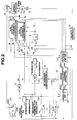
- Fig. 1 is a circuit block diagram of an apparatus for controlling a torque of an induction motor in a first preferred embodiment according to the present invention.
- Fig. 2 is a circuit block diagram of the induction motor torque controlling apparatus in a second preferred embodiment according to the present invention.
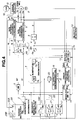
- Fig. 3 is a circuit block diagram of the induction motor torque controlling apparatus in a third preferred embodiment according to the present invention.
- Fig. 4 is a circuit block diagram of the induction motor torque controlling apparatus in a fourth preferred embodiment according to the present invention.
- Fig. 5 is a T-type equivalent circuit diagram of an induction motor to which the apparatus for controlling the torque of the induction motor is applicable.
- Fig. 6 is a T-I type equivalent circuit diagram of the induction motor to which the apparatus for controlling the torque of the induction motor is applicable.
- Fig. 7 is a circuit block diagram of a basic vector control apparatus for the induction motor.
- the torque controlling apparatus adopts the circuit constants in the T-I type equivalent circuit in Fig. 6.
- circuit constants recited in Fig. 5 have been used in the problems to be solved described in the BACKGROUND OF THE INVENTION.
- R 2 denotes a fixed secondary resistance
- M denotes an exciting inductance
- l 1 denotes a primary leakage inductance in Fig.5
- l 2 denotes a secondary leakage inductance in Fig. 5
- L ⁇ denotes the leakage inductance in Fig. 6.
- Fig. 7 shows a basic vector control of a slip frequency type on the basis of which the torque controlling apparatus according to the present invention is established.
- a torque instruction Trq from a speed control system of the induction motor 1 is divided by a secondary magnetic instruction ⁇ 2d * at a divider 2 to derive a torque instruction IT*.
- An exciting current instruction I0* is derived by multiplying and dividing the secondary magnetic flux instruction ⁇ 2d * at a coefficient processor 3.
- These instructions I0* and IT* are compared with detected values Id and Iq of an exciting axis (d) current component and a torque axis (q) current component, both components being orthogonal bi-phase rotational coordinate system rotating in synchronization with a power supply frequency, respectively, to derive their deviations at respective subtractors in a current control (ACR) system 4.
- ACR current control
- the deviations are respectively under proportional-integral (P-I) calculations to derive voltage instructions V 1d and V 1q on an orthogonal bi-phase rotational coordinate system.
- P-I proportional-integral
- a coordinate transformation circuit 5 transforms the bi-phase voltage instruction V 1d and V 1q into tri-phase voltages Vu, Vv, and Vw on a three-phase fixed coordinate system through a bi-phase/tri-phase and rotational coordinate transformation to derive a primary voltage instruction to the induction motor 1.
- the primary voltage instruction is used as an output instruction of a PWM (Pulse Width Modulation) inverter (not shown) on the three-phase fixed coordinate system into currents Id and Iq on the bi-phase rotational coordinate system through a tri-phase/bi-phase and rotational coordinate system.
- PWM Pulse Width Modulation
- a slip calculator 7 calculates a slip frequency component ⁇ s from the secondary magnetic flux instruction ⁇ 2d *, the torque current instruction IT*, and the secondary resistance R 2 of the induction motor 1.
- a reference phase calculator 8 adds a rotor speed detection value ⁇ r of the motor 1 to the slip frequency component ⁇ s to derive a power supply angular frequency ⁇ 1 and integrates the value of ⁇ 1 through 1/ s to derive a reference phase (exciting axis phase) ⁇ 1 and to develop a reference phase ⁇ 1 required to the coordinate transformations at the circuits 5 and 6.
- the rotor speed of the induction motor 1 is detected by a phase pick up 9 axially coupled to the induction motor 1 to derive a pulse train having a frequency proportional to the rotation speed of the rotor and by a speed detector 10 which receives the pulse train from the pick up 9 to detect the rotor speed ⁇ r.
- a denotes a complex variable in the Laplace transform.
- a secondary magnetic flux calculator 11 derives the secondary magnetic flux ⁇ 2d * from the rotor speed ⁇ r.
- An exciting inductance saturation correction circuit 12 corrects the coefficient M' in the coefficient processor 3 according to the rotor speed ⁇ r or magnetic flux instruction.
- the magnetic flux instruction (exciting current component) and torque current component are given to control the torque of the induction motor 1 which correspond to field current and armature current of a DC motor and the slip calculator 7 calculates and controls the slip using the secondary resistance R 2 ' of the induction motor 1.
- Fig. 1 shows a circuit block diagram of the apparatus for controlling the torque of the induction motor through the vector control type inverter in a first preferred embodiment according to the present invention.
- new circuits of a model calculator 14, an error characteristic variable extracting circuit 15, an induced voltage and magnetic flux calculating circuit 13, a secondary resistance variation compensation calculating circuit 16, a skin effect correction circuit 17, and a summer (adder) 17A are provided in the vector control system shown in Fig.7.
- the induced voltage and magnetic flux calculating circuit 13 subtracts the voltage drop components across the primary resistance R 1 and the leakage inductance L ⁇ caused by the output currents (Iu, Iw) or current instructions (Id, Iq) from the output voltage information (Vu, Vv, Vw) to derive the secondary induced voltage E 2 (E 2d , E 2q ) or to derive the secondary magnetic flux ⁇ 2 ( ⁇ 2d, ⁇ 2q ) of the integration of the secondary induced voltage E 2 .
- the model calculator 14 has the model in it and arranged for calculating and outputting the secondary induced voltage E 2 * (E 2d *, E 2q *) (and further calculates the secondary magnetic flux ⁇ 2 * ( ⁇ 2 d*, ⁇ 2 q*) of the model) of the model from the magnetic flux instruction ⁇ 2d *, the torque current instruction IT*, and output frequency ⁇ 1 of the summer 8A before the slip calculator 8.
- the error characteristic variable extracting circuit 15 compares both outputs of the induced voltage and magnetic flux calculation circuit 13 and the model calculator 14 and extracts and outputs the component corresponding to the error component of the secondary resistance R 2 ' to the secondary resistance compensation circuit 16 so as to enable the correction of the secondary resistance R 2 ' used for the slip calculation.
- the secondary resistance circuit 16 multiplies the R 2 ' component in the slip calculator 7 so as to calculate the slip corresponding to the variation in the secondary resistance in the actual induction motor 1.
- a concept of the first embodiment is such that the leakage inductance L ⁇ at the model calculator side is accurately corrected so that the calculated voltage (or magnetic flux) at the model calculator side is made equal to that calculated at the secondary induced voltage and magnetic flux calculation circuit side.
- the non-linearity needs not to be handled in the form of L ⁇ unless the model voltage is used in that other than the compensation for the secondary resistance variation, the non-linear component to be naturally handled as the inductance is corrected as the error component (in a unit of error voltage or error magnetic flux) between those of the model calculator 14 and the secondary induced voltage and magnetic flux calculation circuit 13 which is outputted from the error characteristic variable extracting circuit 15.
- a skin effect correction circuit 17 is added which stores two-dimensional non-linear function and an adder 17A is interposed between the output of the error characteristic variable extracting circuit 15, the skin effect correction circuit 17, and R2' variation compensation circuit 16.
- the skin effect correction circuit 17 receives the detected value of the rotor speed ⁇ r from the velocity (speed) detection circuit 10 and the torque current instruction IT* and outputs the component having the same unit (voltage or magnetic flux) as the output (variable) of the error characteristic variable extracting circuit 15.
- IT* and ⁇ r input variables
- an interpolation of the table or approximation of the function is carried out.
- the adder 17A adds the correction component of the skin effect correction circuit 17 to the output variable of the error characteristic variable extracting circuit 15.
- the correction component derived from the skin effect correction circuit 17 can cancel the error in the corresponding (one) of the parameters or the errors in the parameters.
- the magnetic flux instruction ⁇ 2d* may be inputted to the skin effect correction circuit 17 in place of the detected value ⁇ r of the rotor speed detection circuit 10 and/or the torque current IT may be inputted to the skin effect correction circuit 17 in place of the torque current instruction IT*.
- the skin effect correction circuit 17 has the two-dimensional non-linear function with the torque current instruction IT* and the detected value of the rotor speed ⁇ r as the input variables of the two lateral axes
- a three-dimensional non-linear function table may be used with x-y coorditates set as the input variables IT* and ⁇ r and z coordinate being the output variable of the skin effect correction circuit 17.
- Fig. 2 shows a second preferred embodiment of the induction motor torque controlling apparatus according to the present invention.
- a torque detector 19 detects the load torque from the load facility 18.
- a torque control circuit 20 is added to the structure of the first preferred embodiment shown in Fig. 1 in which the torque instruction Trq is compared with the detected torque of the torque detector 19 at each detected speed of the rotor of the induction motor IM 1 and the output variable of the skin effect correction circuit 17 is further connected so that their values coincide with each other.
- the skin effect correction circuit 17 updates and stores the output value of the torque control circuit 20 as the correction function value of the skin effect correction circuit 17.
- the torque control circuit 20 includes a subtractor 20A arranged for subtracting the detected torque of the torque detector 19 from the torque instruction value Trq and a function table 20B of the output variable of the skin effect correction circuit 17 with respect to a subtraction result of the subtractor 20A.
- the torque control circuit 20 has the function of measuring the torque during the tuning operation and saving the torque or speed variation in a two-dimensional torque.
- a highly accurate torque control can be achieved in either the first or second embodiment for a steady state torque.
- a response delay in the secondary resistance compensation occurs with respect to the variation in the secondary resistance component and, thus, provides a cause of a torque disturbance.
- Fig. 3 shows a third preferred embodiment of the torque controlling apparatus according to the present invention.
- a skin effect transient component correction circuit 21 and a multiplier 22 are added to the circuit structure of the first embodiment shown in Fig. 1.
- the skin effect transient component correction circuit 21 is added in order to compensate for a component corresponding to the variation in the secondary resistance due to the skin effect caused by the variation in the current flowing through the motor 1 in the same way as the skin effect correction circuit 17.
- the skin effect transient component correction circuit 21 has a two-dimensional (or alternatively a three-dimensional) non-linear function table with the detected value ⁇ r of the rotor speed and torque current instruction IT* as inputted data.
- the multiplier 22 multiplies the output of the secondary resistance variation component calculating circuit 16 by the multiplier (correction value) described above.
- the output variable of the skin effect transient component compensation circuit 21 is directly multiplied to the secondary resistance component R 2 ' of 7A in the slip calculator 7 to be corrected in a case where the secondary resistance compensation is not required since a temperature variation of the induction motor 1 is not easy to occur (such a case where the ambient temperature of the motor 1 is air conditioned to maintain a normal temperature so that a temperature rise is rare).
- Fig. 4 shows a fourth preferred embodiment of the induction motor (three-phase) torque controlling apparatus according to the present invention.
- a switch 23 is interposed between the output end of the skin effect transient component correction circuit 21 and the multiplier 22 as described in the third embodiment.
- the tuning of the correction function at a plurality of points is carried out in response to the detected value of the rotor speed and the torque instruction in the same case as the second embodiment.
- the value of KR2 which is the secondary resistance compensation output of the secondary resistance variation compensation circuit 16 is stored in the correction circuit 21 as the correction data.
- the switch 23 is turned to the output side of the skin effect transient component correction circuit 21 to be connected to the multiplier 22.
- the correction circuit 21 outputs the secondary resistance variation component corresponding to the skin effect component in the actual induction motor 1 after the tuning operation. Consequently, if the temperature in the motor 1 is constant, the secondary resistance component output of the compensation circuit 16 is not varied even if the torque instruction is varied so that the compensation circuit 16 compensates only for the secondary resistance circuit component due to the variation in temperature.
- the variation factors in the secondary resistance include the components according to the temperature and according to the skin effect due to the current flowing through the motor 1.
- the compensation circuit 16 side compensates only for the temperature variation and the correction circuit 21 side corrects only the component of the skin effect due to the torque current variation (exciting current variation). Namely, the correction circuits different for each kind of variation factors are prepared and installed. Hence, even during the occurrence in the abrupt variation in the torque instruction, the accurate torque control can be achieved.
- Fig. 6 the PWM inverter, the velocity detection circuit are exemplified by the United States Patent No. 5,341,081 (the disclosure of which is herein incorporated by reference).
- circuit block diagram of Figs. 1 to 4 is drawn in the hardware form, the circuits expect the motor 1 and its peripheral circuits (9, 10, 18, 19) may be constituted by a software which is stored in a control unit for the inverter.
Landscapes
- Engineering & Computer Science (AREA)
- Power Engineering (AREA)
- Control Of Ac Motors In General (AREA)
- Control Of Multiple Motors (AREA)
Applications Claiming Priority (3)
| Application Number | Priority Date | Filing Date | Title |
|---|---|---|---|
| JP27477/96 | 1996-02-15 | ||
| JP2747796 | 1996-02-15 | ||
| JP8027477A JPH09219999A (ja) | 1996-02-15 | 1996-02-15 | 可変速駆動装置 |
Publications (3)
| Publication Number | Publication Date |
|---|---|
| EP0790701A2 true EP0790701A2 (fr) | 1997-08-20 |
| EP0790701A3 EP0790701A3 (fr) | 1997-11-12 |
| EP0790701B1 EP0790701B1 (fr) | 2001-05-16 |
Family
ID=12222207
Family Applications (1)
| Application Number | Title | Priority Date | Filing Date |
|---|---|---|---|
| EP97102224A Expired - Lifetime EP0790701B1 (fr) | 1996-02-15 | 1997-02-12 | Appareil et méthode pour commander le couple des moteurs à induction par un onduleur à commande vectorielle |
Country Status (6)
| Country | Link |
|---|---|
| US (1) | US5811956A (fr) |
| EP (1) | EP0790701B1 (fr) |
| JP (1) | JPH09219999A (fr) |
| KR (1) | KR100222358B1 (fr) |
| AT (1) | ATE201293T1 (fr) |
| DE (1) | DE69704799T2 (fr) |
Cited By (6)
| Publication number | Priority date | Publication date | Assignee | Title |
|---|---|---|---|---|
| WO1999029031A3 (fr) * | 1997-12-03 | 1999-08-12 | Kone Corp | Commande d'un moteur synchrone a aimants permanents |
| US5973474A (en) * | 1997-12-08 | 1999-10-26 | Kabushiki Kaisha Meidensha | Vector control apparatus method for induction motor using magnetic flux observer of full order |
| WO2000013298A1 (fr) * | 1998-08-28 | 2000-03-09 | Northern Magnetics, Inc. | Commande du mouvement de moteur lineaire |
| KR100442494B1 (ko) * | 2002-02-26 | 2004-07-30 | 엘지산전 주식회사 | 인버터의 토오크 제어장치 및 방법 |
| EP2626998A1 (fr) * | 2012-02-10 | 2013-08-14 | Siemens Aktiengesellschaft | Variateur de l'intensité du courant électrique pour une machine électrique et procédé de réglage correspondant |
| US9209735B2 (en) | 2014-01-02 | 2015-12-08 | Abb Technology Ltd | Control system and method for an electric three-phase variable speed motor |
Families Citing this family (22)
| Publication number | Priority date | Publication date | Assignee | Title |
|---|---|---|---|---|
| JP3266175B2 (ja) * | 1996-07-12 | 2002-03-18 | 株式会社安川電機 | 誘導電動機の制御方法及び装置 |
| US5969498A (en) * | 1997-11-19 | 1999-10-19 | Unitrode Corporation | Induction motor controller |
| US6321606B1 (en) * | 1998-07-22 | 2001-11-27 | Fuji Electric Co., Ltd. | Apparatus for calculating torque generated by induction motor |
| US6014007A (en) * | 1998-09-29 | 2000-01-11 | Allen-Bradley Company Llc | Method and apparatus for starting an AC drive into a rotating motor |
| DE60044508D1 (de) | 2000-11-20 | 2010-07-15 | Mitsubishi Electric Corp | Verfahren zur regelung eines induktionsmotors |
| US6459230B1 (en) | 2001-02-13 | 2002-10-01 | Rockwell Automation Technologies, Inc. | Method and system for measuring a parameter of motor operation |
| US7187155B2 (en) * | 2004-05-14 | 2007-03-06 | Rockwell Automation Technologies, Inc. | Leakage inductance saturation compensation for a slip control technique of a motor drive |
| WO2006004037A1 (fr) * | 2004-07-06 | 2006-01-12 | Kabushiki Kaisha Yaskawa Denki | Dispositif inverseur, et procédé de réduction de la vitesse pour un moteur électrique |
| KR100551106B1 (ko) * | 2004-07-16 | 2006-02-09 | 엘에스산전 주식회사 | 온라인상의 부하 상태변동 식별 및 벡터형 인버터 제어기재조절을 위한 장치 및 방법 |
| JP4215025B2 (ja) * | 2005-04-25 | 2009-01-28 | 株式会社デンソー | 車両用発電制御装置 |
| US20070024224A1 (en) * | 2005-07-26 | 2007-02-01 | Mcdonald Raymond G | kW-based torque control for AC motors |
| JP2008086129A (ja) * | 2006-09-28 | 2008-04-10 | Hitachi Ltd | 交流電動機の制御装置および定数測定装置 |
| US7511449B2 (en) * | 2006-10-31 | 2009-03-31 | Caterpillar Inc. | Electric motor system implementing vector and slip control |
| JP4284355B2 (ja) * | 2006-12-28 | 2009-06-24 | 株式会社日立産機システム | 永久磁石モータの高応答制御装置 |
| JP5107581B2 (ja) * | 2007-01-12 | 2012-12-26 | 三菱電機株式会社 | 電気車の制御装置 |
| JP5130031B2 (ja) * | 2007-12-10 | 2013-01-30 | 株式会社日立製作所 | 永久磁石モータの位置センサレス制御装置 |
| US7791328B2 (en) * | 2008-07-03 | 2010-09-07 | Emerson Electric Co. | Method and system for calibrating a motor control circuit to improve temperature measurement in an electrical motor |
| RU2447573C1 (ru) * | 2010-11-02 | 2012-04-10 | Государственное образовательное учреждение Высшего профессионального образования Липецкий государственный технический университет (ГОУ ВПО ЛГТУ) | Электропривод переменного тока |
| RU2512873C1 (ru) * | 2013-01-09 | 2014-04-10 | Федеральное государственное бюджетное образовательное учреждение высшего профессионального образования Липецкий государственный технический университет (ЛГТУ) | Электропривод переменного тока |
| JP5510577B2 (ja) * | 2013-03-11 | 2014-06-04 | 株式会社安川電機 | 誘導電動機のベクトル制御装置 |
| RU180979U1 (ru) * | 2017-12-19 | 2018-07-03 | Федеральное государственное бюджетное образовательное учреждение высшего образования "Липецкий государственный технический университет" | Электропривод переменного тока |
| CN109031953B (zh) * | 2018-07-26 | 2021-10-15 | 上海高适软件有限公司 | 基于自学习的电动升降桌遇阻回退方法和系统及升降设备 |
Family Cites Families (11)
| Publication number | Priority date | Publication date | Assignee | Title |
|---|---|---|---|---|
| JPH07108119B2 (ja) * | 1987-08-08 | 1995-11-15 | 三菱電機株式会社 | 誘導電動機制御装置 |
| US4885518A (en) * | 1987-08-21 | 1989-12-05 | Westinghouse Electric Corp. | Induction motor torque/flux control system |
| US4962339A (en) * | 1987-08-21 | 1990-10-09 | Westinghouse Electric Corp. | Pole-tying current control apparatus |
| US5155797A (en) * | 1987-09-08 | 1992-10-13 | Kabushiki Kaisha Meidensha | Control system for controlling revolution speed of electric motor |
| JPH01209980A (ja) * | 1988-02-18 | 1989-08-23 | Toshiba Corp | 二次回路定数演算装置 |
| US4862054A (en) * | 1988-10-31 | 1989-08-29 | Westinghouse Electric Corp. | Tacho-less vector control adaptive system for motor drive |
| DE69109832T2 (de) * | 1990-12-11 | 1995-10-05 | Meidensha Electric Mfg Co Ltd | Vektorsteuerung. |
| CA2101796C (fr) * | 1992-07-21 | 1996-10-01 | Tetsuo Yamada | Appareil de controle vectoriel pour moteur asynchrone |
| JPH0686581A (ja) * | 1992-07-14 | 1994-03-25 | Meidensha Corp | パラメータの変動補償方法 |
| JPH06153568A (ja) * | 1992-11-13 | 1994-05-31 | Meidensha Corp | 誘導電動機の定数計測方法 |
| EP0608571B1 (fr) * | 1993-01-11 | 1998-03-25 | Kabushiki Kaisha Meidensha | Système de contrÔle vectoriel pour moteur d'induction |
-
1996
- 1996-02-15 JP JP8027477A patent/JPH09219999A/ja active Pending
-
1997
- 1997-02-12 AT AT97102224T patent/ATE201293T1/de not_active IP Right Cessation
- 1997-02-12 EP EP97102224A patent/EP0790701B1/fr not_active Expired - Lifetime
- 1997-02-12 DE DE69704799T patent/DE69704799T2/de not_active Expired - Fee Related
- 1997-02-13 US US08/800,171 patent/US5811956A/en not_active Expired - Lifetime
- 1997-02-15 KR KR1019970004617A patent/KR100222358B1/ko not_active Expired - Fee Related
Cited By (8)
| Publication number | Priority date | Publication date | Assignee | Title |
|---|---|---|---|---|
| WO1999029031A3 (fr) * | 1997-12-03 | 1999-08-12 | Kone Corp | Commande d'un moteur synchrone a aimants permanents |
| US6452357B1 (en) | 1997-12-03 | 2002-09-17 | Kone Corporation | Method for controlling a permanent magnet synchronous motor |
| US5973474A (en) * | 1997-12-08 | 1999-10-26 | Kabushiki Kaisha Meidensha | Vector control apparatus method for induction motor using magnetic flux observer of full order |
| WO2000013298A1 (fr) * | 1998-08-28 | 2000-03-09 | Northern Magnetics, Inc. | Commande du mouvement de moteur lineaire |
| US6215260B1 (en) | 1998-08-28 | 2001-04-10 | Northern Magnetics, Inc. | Controlling movement of linear induction motor |
| KR100442494B1 (ko) * | 2002-02-26 | 2004-07-30 | 엘지산전 주식회사 | 인버터의 토오크 제어장치 및 방법 |
| EP2626998A1 (fr) * | 2012-02-10 | 2013-08-14 | Siemens Aktiengesellschaft | Variateur de l'intensité du courant électrique pour une machine électrique et procédé de réglage correspondant |
| US9209735B2 (en) | 2014-01-02 | 2015-12-08 | Abb Technology Ltd | Control system and method for an electric three-phase variable speed motor |
Also Published As
| Publication number | Publication date |
|---|---|
| KR100222358B1 (ko) | 1999-10-01 |
| DE69704799D1 (de) | 2001-06-21 |
| EP0790701B1 (fr) | 2001-05-16 |
| DE69704799T2 (de) | 2001-08-30 |
| EP0790701A3 (fr) | 1997-11-12 |
| ATE201293T1 (de) | 2001-06-15 |
| JPH09219999A (ja) | 1997-08-19 |
| US5811956A (en) | 1998-09-22 |
| KR970063897A (ko) | 1997-09-12 |
Similar Documents
| Publication | Publication Date | Title |
|---|---|---|
| US5811956A (en) | Apparatus and method for controlling torque of induction motor through vector control type inverter | |
| US6281659B1 (en) | Induction motor drive and a parameter estimation method thereof | |
| JP3815113B2 (ja) | 誘導電動機の制御方法 | |
| EP0942522B1 (fr) | Procédé et dispositif de pilotage d'un moteur à trois phases à enroulements multiplexés | |
| DE4240210C2 (de) | Steuervorrichtung zur feldorientierten Steuerung eines Asynchronmotors | |
| EP0233948B1 (fr) | Procede de commande d'un moteur a induction triphase | |
| EP0637870B1 (fr) | Appareil de commande du vecteur pour un moteur à induction | |
| KR0138730B1 (ko) | 유도 모터용 벡터 제어 시스템 | |
| US20100308757A1 (en) | Alternating-current motor control apparatus | |
| JPH07110160B2 (ja) | 誘導電動機の制御装置 | |
| US5119007A (en) | Inverter control apparatus | |
| US6611124B2 (en) | Control apparatus of induction motor | |
| EP1128545B1 (fr) | Procédé de contrôle d'un moteur à induction | |
| JPH11187699A (ja) | 誘導電動機の速度制御方法 | |
| US6075337A (en) | Speed control apparatus for induction motor | |
| JP3337039B2 (ja) | 誘導電動機のベクトル制御インバータのチューニング方法 | |
| JP3351244B2 (ja) | 誘導電動機の速度制御方法 | |
| KR0129561B1 (ko) | 유도 모터용 벡터 제어 장치 | |
| JP3736551B2 (ja) | 誘導電動機の速度制御方法 | |
| US20230216439A1 (en) | Motor iron-loss calculation device and motor control device comprising same | |
| JPH08331899A (ja) | 交流電動機の可変速制御装置 | |
| JP2712632B2 (ja) | 誘導電動機の可変速制御装置 | |
| JP3032681B2 (ja) | 誘導電動機の二次抵抗測定方法およびその装置 | |
| JP2590524B2 (ja) | ベクトル制御装置 | |
| JPH02241389A (ja) | 誘導電動機のベクトル制御装置 |
Legal Events
| Date | Code | Title | Description |
|---|---|---|---|
| PUAI | Public reference made under article 153(3) epc to a published international application that has entered the european phase |
Free format text: ORIGINAL CODE: 0009012 |
|
| 17P | Request for examination filed |
Effective date: 19970212 |
|
| AK | Designated contracting states |
Kind code of ref document: A2 Designated state(s): AT DE FR GB IT |
|
| PUAL | Search report despatched |
Free format text: ORIGINAL CODE: 0009013 |
|
| AK | Designated contracting states |
Kind code of ref document: A3 Designated state(s): AT DE FR GB IT |
|
| 17Q | First examination report despatched |
Effective date: 19990701 |
|
| GRAG | Despatch of communication of intention to grant |
Free format text: ORIGINAL CODE: EPIDOS AGRA |
|
| GRAG | Despatch of communication of intention to grant |
Free format text: ORIGINAL CODE: EPIDOS AGRA |
|
| GRAH | Despatch of communication of intention to grant a patent |
Free format text: ORIGINAL CODE: EPIDOS IGRA |
|
| GRAH | Despatch of communication of intention to grant a patent |
Free format text: ORIGINAL CODE: EPIDOS IGRA |
|
| GRAA | (expected) grant |
Free format text: ORIGINAL CODE: 0009210 |
|
| AK | Designated contracting states |
Kind code of ref document: B1 Designated state(s): AT DE FR GB IT |
|
| REF | Corresponds to: |
Ref document number: 201293 Country of ref document: AT Date of ref document: 20010615 Kind code of ref document: T |
|
| ITF | It: translation for a ep patent filed | ||
| REF | Corresponds to: |
Ref document number: 69704799 Country of ref document: DE Date of ref document: 20010621 |
|
| ET | Fr: translation filed | ||
| REG | Reference to a national code |
Ref country code: GB Ref legal event code: IF02 |
|
| PLBE | No opposition filed within time limit |
Free format text: ORIGINAL CODE: 0009261 |
|
| STAA | Information on the status of an ep patent application or granted ep patent |
Free format text: STATUS: NO OPPOSITION FILED WITHIN TIME LIMIT |
|
| 26N | No opposition filed | ||
| PGFP | Annual fee paid to national office [announced via postgrant information from national office to epo] |
Ref country code: GB Payment date: 20040119 Year of fee payment: 8 |
|
| PGFP | Annual fee paid to national office [announced via postgrant information from national office to epo] |
Ref country code: FR Payment date: 20040217 Year of fee payment: 8 |
|
| PGFP | Annual fee paid to national office [announced via postgrant information from national office to epo] |
Ref country code: AT Payment date: 20040220 Year of fee payment: 8 |
|
| PGFP | Annual fee paid to national office [announced via postgrant information from national office to epo] |
Ref country code: DE Payment date: 20040315 Year of fee payment: 8 |
|
| PG25 | Lapsed in a contracting state [announced via postgrant information from national office to epo] |
Ref country code: IT Free format text: LAPSE BECAUSE OF NON-PAYMENT OF DUE FEES;WARNING: LAPSES OF ITALIAN PATENTS WITH EFFECTIVE DATE BEFORE 2007 MAY HAVE OCCURRED AT ANY TIME BEFORE 2007. THE CORRECT EFFECTIVE DATE MAY BE DIFFERENT FROM THE ONE RECORDED. Effective date: 20050212 Ref country code: GB Free format text: LAPSE BECAUSE OF NON-PAYMENT OF DUE FEES Effective date: 20050212 Ref country code: AT Free format text: LAPSE BECAUSE OF NON-PAYMENT OF DUE FEES Effective date: 20050212 |
|
| PG25 | Lapsed in a contracting state [announced via postgrant information from national office to epo] |
Ref country code: DE Free format text: LAPSE BECAUSE OF NON-PAYMENT OF DUE FEES Effective date: 20050901 |
|
| GBPC | Gb: european patent ceased through non-payment of renewal fee |
Effective date: 20050212 |
|
| PG25 | Lapsed in a contracting state [announced via postgrant information from national office to epo] |
Ref country code: FR Free format text: LAPSE BECAUSE OF NON-PAYMENT OF DUE FEES Effective date: 20051031 |
|
| REG | Reference to a national code |
Ref country code: FR Ref legal event code: ST Effective date: 20051031 |