EP0790755A2 - Dispositif d'éclairage pour four à micro-ondes - Google Patents
Dispositif d'éclairage pour four à micro-ondes Download PDFInfo
- Publication number
- EP0790755A2 EP0790755A2 EP97300933A EP97300933A EP0790755A2 EP 0790755 A2 EP0790755 A2 EP 0790755A2 EP 97300933 A EP97300933 A EP 97300933A EP 97300933 A EP97300933 A EP 97300933A EP 0790755 A2 EP0790755 A2 EP 0790755A2
- Authority
- EP
- European Patent Office
- Prior art keywords
- cooking chamber
- lamp
- lighting device
- hole
- set forth
- Prior art date
- Legal status (The legal status is an assumption and is not a legal conclusion. Google has not performed a legal analysis and makes no representation as to the accuracy of the status listed.)
- Withdrawn
Links
Images

Classifications
-
- F—MECHANICAL ENGINEERING; LIGHTING; HEATING; WEAPONS; BLASTING
- F24—HEATING; RANGES; VENTILATING
- F24C—DOMESTIC STOVES OR RANGES ; DETAILS OF DOMESTIC STOVES OR RANGES, OF GENERAL APPLICATION
- F24C7/00—Stoves or ranges heated by electric energy
- F24C7/02—Stoves or ranges heated by electric energy using microwaves
-
- H—ELECTRICITY
- H05—ELECTRIC TECHNIQUES NOT OTHERWISE PROVIDED FOR
- H05B—ELECTRIC HEATING; ELECTRIC LIGHT SOURCES NOT OTHERWISE PROVIDED FOR; CIRCUIT ARRANGEMENTS FOR ELECTRIC LIGHT SOURCES, IN GENERAL
- H05B6/00—Heating by electric, magnetic or electromagnetic fields
- H05B6/64—Heating using microwaves
- H05B6/6444—Aspects relating to lighting devices in the microwave cavity
-
- H—ELECTRICITY
- H05—ELECTRIC TECHNIQUES NOT OTHERWISE PROVIDED FOR
- H05B—ELECTRIC HEATING; ELECTRIC LIGHT SOURCES NOT OTHERWISE PROVIDED FOR; CIRCUIT ARRANGEMENTS FOR ELECTRIC LIGHT SOURCES, IN GENERAL
- H05B6/00—Heating by electric, magnetic or electromagnetic fields
- H05B6/64—Heating using microwaves
- H05B6/76—Prevention of microwave leakage, e.g. door sealings
Definitions
- the present invention generally relates to a microwave oven comprising a cooking chamber and a filament lamp for illuminating the cooking chamber through an aperture in a wall thereof.
- a microwave oven heats food by using microwaves at approximately 2 450 MHz, usually generated by a magnetron.
- the microwaves are radiated into a cooking chamber in which the food food has been placed.
- Polar molecules e.g. water molecules, in the food are drawn into alignment with the electric field of the microwave radiation.
- the rapid oscillation of the electric field of the microwaves causes the molecules to collide with each other, generating heat which warms the food.
- radiant electric heaters have been incorporated into microwave ovens to supplement the cooking process.
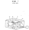
- FIG. 7 is a cutaway-perspective view of a conventional microwave oven as disclosed in JP-A-06-59707.
- the oven includes a cooking chamber 1 in which food is cooked, a magnetron 3 which produces microwaves to cook the food, a plurality of holes formed in the upper section of the cooking chamber 1, and a lamp 13 installed over the holes 12 which illuminates the cooking chamber 1 therethrough.
- the degree of illumination of the cooking chamber 1 by the lamp 13 is proportional to the size of the holes 12. However, their size is limited by the possibility of microwave leakage through the holes 12. Also, the height of the lamp 13 above the cooking chamber 1 further decreases the illumination therein. Thus, food in the cooking chamber 1 is insufficiently illuminated the user cannot easily monitor the progression of the cooking process.
- the present invention is a lighting device for a microwave oven that can obviate the above problems and disadvantages of the conventional technique.
- a microwave oven according to the present invention is characterised in that the lamp illuminates the cooking chamber through a single aperture and the filament of the lamp is positioned relative to the aperture such that less than 2.0mW cm -2 of microwave power leaks through the hole when the oven is in use.
- An oven according to the present invention may include a further filament lamp for illuminating the cooking chamber through an aperture in a wall thereof.
- the lamps preferably generate light having different colours.
- the or each aperture is provided in an upper wall of the cooking chamber. More preferably, the or each aperture is formed substantially on the front-to-rear centre line of the upper wall.
- One lamp may be advantageously positioned approximately 2 / 14 th of the distance, from the front of the cooking chamber, along the front-to-rear centre line of an upper wall of the chamber.
- the front margin of an upper wall of the cooking chamber slopes downwardly and the aperture is formed in said front margin so that light from the lamp is directed to a back wall of the cooking chamber.
- the diameter of the or each aperture is in the range 14mm to 19mm.
- a glass cover is provided for protecting the or each lamp and the cover protrudes through the associated aperture or apertures into the cooking chamber.
- the filament of the or each lamp is spaced approximately 2mm perpendicularly away from the opening of the aperture in the outer surface of said wall.
- Reflector means may be provided to maximize the amount of light passing through the or each aperture.
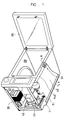
- the microwave oven includes a cooking chamber 20 and a door 50 that opens and closes the entrance to the cooking chamber 20.
- the cooking chamber 20 is formed by an inner case 11, and this inner case 11 is joined to an outer case 12 to constitute the main body of the microwave oven.
- a rotatable tray is is located at the bottom of the cooking chamber 20 and is turned by an electric motor (not shown).
- An electrical component compartment 30 is formed between the inner case 11 and the outer case 12.
- the electrical component compartment 30 houses a magnetron 31 which is powered by a high voltage transformer 32 and which radiates microwaves into the cooking chamber 20 so as to cook foods therein. Behind the electrical component compartment 30 is a fan 33 which cools the high-voltage transformer 32.
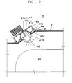
- a lighting device 40 is provided on the upper surface 21 of the cooking chamber 20 to illuminate the cooking chamber's 20 interior.
- the upper surface 21 has a beveled portion 21a at its front onto which the lighting device 40 is mounted.
- This beveled portion 21a has the slopes most at the rearmost part when viewed from the top.
- the lighting device 40 is installed on the beveled portion 21a perpendicular to its surface, facing towards the cooking chamber 20.
- the beveled portion 21a has a hole 21b formed in its centre through which light rays from the lighting device 40 pass.
- the lighting device 40 is installed outside the hole 21b and is turned on and off by means of an electrical connection with a circuit board (not not shown) in the electrical component compartment 30.
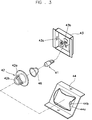
- the lighting device 40 includes a lamp 41 consisting of a filament 41a that emits light when power is applied to it, a terminal 41b through which electricity is supplied to the filament 41a, and a bulb 41c.
- Lamp brackets 44 on which the lamp 41 is installed are fixed on the beveled portion 21a and, being fixed by rivets 45, are designed to lie flush with the beveled portion 21a and its peripheral portion.
- each lamp bracket 44 has a guide piece 44a that protrudes upwards, securing a lamp cover 43 which is put on the lamp 41 in place.
- the lamp cover 43 is in the shape of a box whose bottom is open, and has apertures 43a formed on each of its sides.
- First bosses 44b, formed on each of the guide pieces 44a of the lamp bracket 44, are respectively inserted into the apertures 43a in such a manner that the lamp cover 43 is connected to the lamp brackets 44.
- the lamp 41 is fixed to the lamp cover 43, and the filament's 41a lower end extends outside the beveled portion 21a.
- a protective glass 42 is mounted on the hole 21b to provide protection for the lamp 41 by protruding into the cooking chamber 20 and making the lamp 41 watertight, thus precluding disconnection of the lamp 41 due to moisture.
- the protective glass 42 also stops dirt and dust from directly adhering to the lamp 41 to thereby avoid damage to the lamp 41.
- the protective glass 42 which is made of heat-resistant glass, serves to diffuse light rays from the lamp 41.
- the protecting glass 42 includes a flange 42a lying on the outer surface of the beveled portion 21a, and a convex portion 42b protruding into the cooking chamber 20 from the flange 42a, passing through the hole 21b.
- a cone-shaped reflecting member 46 which reflects light lays from the lamp 41 toward the cooking chamber 20, is provided to the interior of the lamp cover 43 so as to encircle the lamp 41.
- the reflecting member's 46 lower end comes in contact with the protective glass 42, and its upper end contacts the lamp's 41 inner surface.
- Second bosses 43b are provided on the inner side of the lamp cover 43 within which the reflecting member 46's upper end is secured.
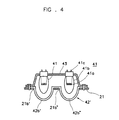
- FIGS. 4 and 5 depict lighting devices for a microwave oven in accordance the present invention.
- a plurality of holes 21b' and 21b" are formed in the beveled portion 21a, and at least one lamp 41 is provided to each hole 21b' and 21b".
- the filament's 41a lower end is positioned outside the beveled portion 21a, and a bulb's 41b lower end protrudes into the cooking chamber 20.
- Figure 4 shows a lighting device in which a lamp 41 is provided at each of the holes 21b' and 21b", and Figure 5 depicts a lighting device in which two lamps 41 are provided at one hole 21b' and one lamp 41 is provided at the other hole 21b".
- the two lamps 41 at the hole 21b' provide white light
- one lamp 41 at the hole 21b" produces red light.
- a partition 47 is formed between these lamps 41, thus offering two-color lighting.
- the following description relates to the operation of a microwave oven according to the present invention.
- the magnetron 31 radiates microwaves into the cooking chamber 20 which cook food therein.
- a fan 33 is provided to cool the high-voltage transformer 32 and the magnetron 31 with air from outside the oven.
- the lamp 41 is turned on during the cooking operation and light rays from the lamp 41 are diffused through the protective glass 42 into the cooking chamber 20 so that the intensity of the light provided to the cooking chamber 20 is increased.
- the lamp's 41 placement on the front of the cooking chamber's 20 upper portion so as to face the rear additionally enhances illumination of the cooking chamber 20. Most light rays generated by the lamp 41 are directly provided to the cooking chamber 20, and the rest is reflected by the reflecting member 46 into the cooking chamber 20, thus providing increased illumination in the cooking chamber 20.
- Table 1 - 1 represents the relationship between the level of illumination of the cooking chamber 20 and the diameter ( ⁇ ) of the hole 21b, the amount of microwave leakage and the lifetime of the lamp (numerical values of Table 1 - 1 reflect experimental results).
- the amount of leakage exceeds a predetermined value (6mW cm -2 )
- the lifetime of the lamp 41 is reduced.
- the diameter ⁇ of the hole 21b be about 14mm - 19mm.
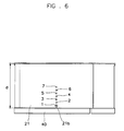
- Figure 6 shows various positions of the hole 21b.
- Seven holes 21b are formed in the middle of the upper surface 21. More specifically, according to experimental data, the holes 21b are respectively formed at 1/14, 2/14,..., 6/14 and 7/14 of the depth of the upper surface 21 from the front of the upper surface 21. In the experiment, the filament 41a is positioned level with, 3mm below, 1mm above, or 2mm above the upper surface 21.
- Table 2 - 2 represents the illumination levels in the cooking chamber 20 under different conditions.
- the lighting efficiency of the lamp 41 provided at the hole 21b which is in the centre of the upper surface 21, reaches its highest level.
- the lighting efficiency of the lamp 41 provided at the hole 21b at the second position 2/14 reaches the highest level. Therefore, the lamp 41 is preferably installed at the second position 2/14.
- a lamp is installed on the upper surface of the cooking chamber in close vicinity to the cooking chamber and most light rays from the lamp are provided directly to the cooking chamber, thus offering enhanced lighting efficiency.
- the light from the lamp is diffused by the protective glass that protrudes into the cooking chamber to thereby illuminate the cooking chamber more efficiently.
- the light directed initially away from the cooking chamber is reflected by the reflecting member into the cooking chamber which enhances the lighting efficiency of the lamp.
- the lamp is installed in a position which ensures enhanced lighting efficiency and the diameter of the hole is as large as possible within the range in which the microwave leakage is acceptable.
- it is simple to install a lighting device according to the present invention on the top of the inner case of the microwave oven.
Landscapes
- Physics & Mathematics (AREA)
- Electromagnetism (AREA)
- Engineering & Computer Science (AREA)
- Chemical & Material Sciences (AREA)
- Combustion & Propulsion (AREA)
- Mechanical Engineering (AREA)
- General Engineering & Computer Science (AREA)
- Electric Ovens (AREA)
- Constitution Of High-Frequency Heating (AREA)
- Electric Stoves And Ranges (AREA)
Applications Claiming Priority (2)
| Application Number | Priority Date | Filing Date | Title |
|---|---|---|---|
| KR1019960003568A KR970062507A (ko) | 1996-02-14 | 1996-02-14 | 전자렌지의 조명장치 |
| KR9603568 | 1996-02-14 |
Publications (2)
| Publication Number | Publication Date |
|---|---|
| EP0790755A2 true EP0790755A2 (fr) | 1997-08-20 |
| EP0790755A3 EP0790755A3 (fr) | 1998-01-07 |
Family
ID=19451237
Family Applications (1)
| Application Number | Title | Priority Date | Filing Date |
|---|---|---|---|
| EP97300933A Withdrawn EP0790755A3 (fr) | 1996-02-14 | 1997-02-13 | Dispositif d'éclairage pour four à micro-ondes |
Country Status (4)
| Country | Link |
|---|---|
| EP (1) | EP0790755A3 (fr) |
| JP (1) | JPH09229376A (fr) |
| KR (1) | KR970062507A (fr) |
| CA (1) | CA2197392A1 (fr) |
Cited By (2)
| Publication number | Priority date | Publication date | Assignee | Title |
|---|---|---|---|---|
| EP1542512A3 (fr) * | 2003-12-10 | 2008-01-16 | Samsung Electronics Co., Ltd. | Dispositif de cuisson possédant un ensemble lampe |
| EP2302304A1 (fr) * | 2009-09-26 | 2011-03-30 | Electrolux Home Products Corporation N.V. | Four avec au moins une cavité du four éclairée |
Families Citing this family (3)
| Publication number | Priority date | Publication date | Assignee | Title |
|---|---|---|---|---|
| KR100533271B1 (ko) * | 1998-07-29 | 2006-09-20 | 주식회사 엘지이아이 | 마이크로웨이브 차단장치를 구비한 전자레인지 |
| JP5747162B2 (ja) * | 2011-07-26 | 2015-07-08 | パナソニックIpマネジメント株式会社 | 高周波調理器 |
| JP7345084B2 (ja) * | 2020-04-03 | 2023-09-15 | パナソニックIpマネジメント株式会社 | 加熱調理器 |
Family Cites Families (10)
| Publication number | Priority date | Publication date | Assignee | Title |
|---|---|---|---|---|
| JPS51131638A (en) * | 1975-05-13 | 1976-11-16 | Nippon Telegr & Teleph Corp <Ntt> | Multiple electric conductor transmitter |
| JPS51143274A (en) * | 1975-06-02 | 1976-12-09 | Tsubakimoto Chain Co | Transfer device between carriage conveyors |
| SE444061B (sv) * | 1983-03-23 | 1986-03-17 | Philips Norden Ab | Belysningsanordning vid mikrovagsugnar |
| DE3606421C1 (de) * | 1986-02-27 | 1987-04-09 | Bosch Siemens Hausgeraete | Beleuchtungseinrichtung fuer einen Mikrowellenherd |
| DE3641420A1 (de) * | 1986-12-04 | 1988-06-09 | Licentia Gmbh | Mikrowellenherd |
| DE3703937C2 (de) * | 1987-02-09 | 1994-05-05 | Bosch Siemens Hausgeraete | Mikrowellenherd |
| DE3742518A1 (de) * | 1987-12-15 | 1989-06-29 | Bosch Siemens Hausgeraete | Beleuchtungseinrichtung fuer einen mit mikrowellenenergie beaufschlagbaren ofen, insbesondere einen haushalts-backofen |
| SE464383B (sv) * | 1989-07-18 | 1991-04-15 | Whirlpool Int | Mikrovaagsugn med en belysningsanordning foer upplysning av ungskaviteten |
| DE9000951U1 (de) * | 1990-01-29 | 1990-04-05 | Brökelmann, Jaeger & Busse GmbH & Co, 5760 Arnsberg | Mikrowellendichte Leuchte, insbesondere für Herde |
| DE4003736A1 (de) * | 1990-02-08 | 1991-08-14 | Miele & Cie | Beleuchtungseinrichtung fuer mikrowellenherde |
-
1996
- 1996-02-14 KR KR1019960003568A patent/KR970062507A/ko not_active Ceased
-
1997
- 1997-02-12 CA CA002197392A patent/CA2197392A1/fr not_active Abandoned
- 1997-02-13 EP EP97300933A patent/EP0790755A3/fr not_active Withdrawn
- 1997-02-14 JP JP9030959A patent/JPH09229376A/ja active Pending
Cited By (7)
| Publication number | Priority date | Publication date | Assignee | Title |
|---|---|---|---|---|
| EP1542512A3 (fr) * | 2003-12-10 | 2008-01-16 | Samsung Electronics Co., Ltd. | Dispositif de cuisson possédant un ensemble lampe |
| EP2302304A1 (fr) * | 2009-09-26 | 2011-03-30 | Electrolux Home Products Corporation N.V. | Four avec au moins une cavité du four éclairée |
| WO2011035868A1 (fr) * | 2009-09-26 | 2011-03-31 | Electrolux Home Products Corporation N.V. | Four avec au moins une cavité de four éclairée |
| EP2322861A1 (fr) * | 2009-09-26 | 2011-05-18 | Electrolux Home Products Corporation N.V. | Paroi supérieure d'un moufle pour un four de cuisson |
| US20120167865A1 (en) * | 2009-09-26 | 2012-07-05 | Electrolux Home Products Corporation N.V. | Oven with at least one illuminated oven cavity |
| AU2010297629B2 (en) * | 2009-09-26 | 2015-03-19 | Electrolux Home Products Corporation N.V. | An oven with at least one illuminated oven cavity |
| US9995491B2 (en) | 2009-09-26 | 2018-06-12 | Electrolux Home Products Corporation N.V. | Oven with at least one illuminated oven cavity |
Also Published As
| Publication number | Publication date |
|---|---|
| EP0790755A3 (fr) | 1998-01-07 |
| JPH09229376A (ja) | 1997-09-05 |
| KR970062507A (ko) | 1997-09-12 |
| CA2197392A1 (fr) | 1997-08-15 |
Similar Documents
| Publication | Publication Date | Title |
|---|---|---|
| US5805769A (en) | Adjustable ellipsoidal reflector for food heating apparatus | |
| CN101086341B (zh) | 加热烹调器 | |
| EP3376116B1 (fr) | Appareil de cuisson étant doté d'un dispositif d'éclairage | |
| US4421968A (en) | Microwave oven having rotating conductive radiators | |
| JPS6334426A (ja) | 食物を焼くかあるいは褐色に焦がすための装置 | |
| BR0007413A (pt) | Varredura de forno de onda leve e método de operação do mesmo | |
| KR20010083892A (ko) | 브라우닝 장치를 갖춘 극초단파 오븐 | |
| US4621180A (en) | Cavity illumination means for microwave oven | |
| EP0790755A2 (fr) | Dispositif d'éclairage pour four à micro-ondes | |
| AU2004282483B2 (en) | Microwave oven and radiating structure of microwave in microwave oven | |
| US20250198627A1 (en) | Cooking apparatus | |
| TW201636551A (zh) | 加熱調理器 | |
| GB2039200A (en) | Microwave oven | |
| JP2544965Y2 (ja) | マイクロ波オーブン | |
| CN1162722A (zh) | 微波炉照明装置 | |
| JP2005098601A (ja) | 加熱調理器 | |
| KR200142131Y1 (ko) | 전자렌지의 스트러팬에 내설된 조명등 | |
| CN217338183U (zh) | 一种烹饪器具 | |
| KR100693157B1 (ko) | 전자레인지의 램프설치장치 | |
| JPH0552355A (ja) | 調理器 | |
| JP2017003153A (ja) | 高周波加熱調理器 | |
| KR19990030582U (ko) | 전자렌지용 히터의 고정 브라켓 | |
| KR200150904Y1 (ko) | 전자렌지의 조명장치 | |
| KR100662304B1 (ko) | 전자 레인지 | |
| KR19980010345U (ko) | 전자렌지의 조명장치 |
Legal Events
| Date | Code | Title | Description |
|---|---|---|---|
| PUAI | Public reference made under article 153(3) epc to a published international application that has entered the european phase |
Free format text: ORIGINAL CODE: 0009012 |
|
| AK | Designated contracting states |
Kind code of ref document: A2 Designated state(s): DE FR GB |
|
| PUAL | Search report despatched |
Free format text: ORIGINAL CODE: 0009013 |
|
| AK | Designated contracting states |
Kind code of ref document: A3 Designated state(s): DE FR GB |
|
| 17P | Request for examination filed |
Effective date: 19980121 |
|
| 17Q | First examination report despatched |
Effective date: 19980728 |
|
| STAA | Information on the status of an ep patent application or granted ep patent |
Free format text: STATUS: THE APPLICATION IS DEEMED TO BE WITHDRAWN |
|
| 18D | Application deemed to be withdrawn |
Effective date: 19981208 |
|
| RIN1 | Information on inventor provided before grant (corrected) |
Inventor name: KIM, KWANG-HO Inventor name: HONG, SEOK-WEON |