EP0791457A2 - Appareil de formation d'images comportant une cartouche d'encre prévenant la détérioration de l'élément chauffant par l'encre et cartouche d'encre pour cet appareil - Google Patents
Appareil de formation d'images comportant une cartouche d'encre prévenant la détérioration de l'élément chauffant par l'encre et cartouche d'encre pour cet appareil Download PDFInfo
- Publication number
- EP0791457A2 EP0791457A2 EP97301255A EP97301255A EP0791457A2 EP 0791457 A2 EP0791457 A2 EP 0791457A2 EP 97301255 A EP97301255 A EP 97301255A EP 97301255 A EP97301255 A EP 97301255A EP 0791457 A2 EP0791457 A2 EP 0791457A2
- Authority
- EP
- European Patent Office
- Prior art keywords
- ink
- recited
- supply port
- image forming
- forming apparatus
- Prior art date
- Legal status (The legal status is an assumption and is not a legal conclusion. Google has not performed a legal analysis and makes no representation as to the accuracy of the status listed.)
- Withdrawn
Links
Images


Classifications
-
- B—PERFORMING OPERATIONS; TRANSPORTING
- B41—PRINTING; LINING MACHINES; TYPEWRITERS; STAMPS
- B41J—TYPEWRITERS; SELECTIVE PRINTING MECHANISMS, i.e. MECHANISMS PRINTING OTHERWISE THAN FROM A FORME; CORRECTION OF TYPOGRAPHICAL ERRORS
- B41J2/00—Typewriters or selective printing mechanisms characterised by the printing or marking process for which they are designed
- B41J2/005—Typewriters or selective printing mechanisms characterised by the printing or marking process for which they are designed characterised by bringing liquid or particles selectively into contact with a printing material
- B41J2/01—Ink jet
- B41J2/17—Ink jet characterised by ink handling
- B41J2/175—Ink supply systems ; Circuit parts therefor
- B41J2/17503—Ink cartridges
- B41J2/17513—Inner structure
-
- B—PERFORMING OPERATIONS; TRANSPORTING
- B41—PRINTING; LINING MACHINES; TYPEWRITERS; STAMPS
- B41J—TYPEWRITERS; SELECTIVE PRINTING MECHANISMS, i.e. MECHANISMS PRINTING OTHERWISE THAN FROM A FORME; CORRECTION OF TYPOGRAPHICAL ERRORS
- B41J2/00—Typewriters or selective printing mechanisms characterised by the printing or marking process for which they are designed
- B41J2/005—Typewriters or selective printing mechanisms characterised by the printing or marking process for which they are designed characterised by bringing liquid or particles selectively into contact with a printing material
- B41J2/01—Ink jet
- B41J2/015—Ink jet characterised by the jet generation process
- B41J2/04—Ink jet characterised by the jet generation process generating single droplets or particles on demand
- B41J2/06—Ink jet characterised by the jet generation process generating single droplets or particles on demand by electric or magnetic field
- B41J2002/061—Ejection by electric field of ink or of toner particles contained in ink
-
- B—PERFORMING OPERATIONS; TRANSPORTING
- B41—PRINTING; LINING MACHINES; TYPEWRITERS; STAMPS
- B41J—TYPEWRITERS; SELECTIVE PRINTING MECHANISMS, i.e. MECHANISMS PRINTING OTHERWISE THAN FROM A FORME; CORRECTION OF TYPOGRAPHICAL ERRORS
- B41J2202/00—Embodiments of or processes related to ink-jet or thermal heads
- B41J2202/01—Embodiments of or processes related to ink-jet heads
- B41J2202/05—Heads having a valve
Definitions
- the present invention relates to image forming apparatuses including a copying machine, a facsimile and a printer, and more particularly to an image forming apparatus having an ink cartridge detachably mounted to a printing head unit for forming a prescribed image and an ink cartridge thereof.
- sublimation method a method of ejecting vaporized ink to adhere onto a recording medium. According to this sublimation method, clogging of nozzles for ejecting ink is less likely to occur because vaporized ink is ejected. In addition, higher resolution and excellent gradation can be achieved because an image is recorded in the molecular state, allowing high quality print with less blur.
- Image forming apparatus 100 includes a printing head unit 101, and an ink cartridge unit 102 for supplying ink into printing head unit 101.
- Ink cartridge unit 102 includes a cartridge 103 and a liquidizing heater 104.
- Cartridge 103 has a supply port 105.
- Printing head unit 101 includes a supply path 106, a supply heater 107 and a vaporizing heater 108.
- Printing head unit 101 has an ejection port 109.
- Powdery ink IP is stored in cartridge 102.
- Liquidizing heater 104 for liquidizing powdery ink IP is provided at the lower portion of cartridge 102. At the time of printing, liquidizing heater 104 heats powdery ink IP into liquid, supplying ink into printing head unit 101.
- a capillary or fibrous filter which is not shown is provided at supply port 105 so that only liquid ink IPW passes through supply port 105.
- Liquid ink IPW supplied into printing head unit 101 is supplied through supply path 106 to vaporizing heater 108. Liquid ink IPW passes through supply path 106 while having its temperature maintained by supply heater 107 provided at a sidewall of supply path 106. Thus, liquid ink IPW is prevented from becoming solid, thereby avoiding the clogging.
- Liquid ink IPW is heated and vaporized by vaporizing heater 108 which is driven based on a signal corresponding to image data to be recorded.
- Liquid ink IPW is held by a liquid holder (not shown) provided in the vicinity of vaporizing heater 108.
- the liquid holder uses a material having continuous pores such as beading and fiber.
- Vaporized ink IPG is ejected from ejection port 109 by air flow caused by expansion in vaporization.
- Image forming apparatus 200 includes a printing head unit 201, and an ink cartridge 202 for supplying ink into printing head unit 201.
- Ink cartridge unit 202 includes a cartridge 203.
- Cartridge 203 has a supply port 205.
- Printing head unit 201 includes a supply path 206, a powder transporting unit 207 and a vaporizing heater 208.
- Printing head unit 201 has an ejection port 209.
- Powdery ink IP is stored in cartridge 203. Powdery ink IP supplied from supply port 205 into printing head unit 201 is transported by powder transporting unit 207 to pass through supply path 206 to vaporizing heater 208. Powder transporting unit 207 transports powdery ink IP toward vaporizing heater 208 by reciprocation of a driving motor (not shown). Powdery ink IP thus transported is heated and vaporized by vaporizing heater 208 which is driven based on a signal corresponding to image data to be recorded, and then ejected from ejection port 209.
- the above image forming apparatus of Japanese Patent laying-Open No. 7-52423 requires heaters of three kinds, that is, for liquidizing, supplying and vaporizing, to eject ink, resulting in a complicated apparatus. This also involves increase in size of a power supply for the heaters, which increases energy necessary for printing. Furthermore, the residue resulting from vaporization of ink adheres to the vaporizing heater, resulting in deterioration of the vaporizing heater.
- the image forming apparatus of Japanese Patent Laying-Open No. 6-179265 transports powder and therefore requires a supply path having a larger cross section than that in the case of liquid ink. In addition, a transporting apparatus is necessary, resulting in increase in size of the whole apparatus. Furthermore, since powder is directly vaporized in response to the printing timing, powder must be vaporized in a short time. Therefore, a load on the vaporizing heater is increased, which means that adhesion of the residue to the vaporizing heater has a more serious effect on the apparatus compared to the above-described image forming apparatus.
- the image forming apparatus includes a printing head unit 60, a recording medium RM and a back electrode 14.
- Printing head unit 60 includes a heating apparatus 30, a charging electrode 10 and an electric field shutter electrode 11.
- Heating apparatus 30 includes a vaporizing heater 9.
- Powdery ink IP is stored in printing head unit 60.
- Printing head unit 60 is provided with heating apparatus 30 constituted by a heat-radiative plate (not shown) and vaporizing heater 9 for heating and vaporizing powdery ink IP, a thin wire electrode having a diameter in the range from 50 to 80 ⁇ m and serving as charging electrode 10 for charging gaseous ink IPG vaporized by vaporizing heater 9, and a plurality of ejecting ports 7 for ejecting gaseous ink IPG, and electric field shutter electrodes 11 are provided respectively surrounding the plurality of ejecting ports 7.
- powdery ink IP is heated and vaporized by heating apparatus 30.
- coloring materials for the ink anthraisothiazole family, quinophtalon family, pyrazolone family, pyridonazo family, styryl family or the like can be used for yellow; anthraquinone family, dicyanoimidazole family, thiadiazoleazo family, tricyanovinyl family or the like can be used for magenta; and azo family, anthraquinone family, napthoquinone family, indoaniline family or the like can be used for cyan.
- Powdery ink IP is vaporized to gaseous ink IPG.
- a voltage in the range from +2 to 5 kV is applied to charging electrode 10, whereby corona discharge occurs toward heating apparatus 30 being grounded, and gaseous ink IPG is positively charged.
- a negative voltage is applied to back electrode 14 provided over the rear surface of the printing surface of recording medium RM, whereby gaseous ink IPG thus charged is attracted toward the recording medium.
- gaseous ink IPG positively charged cannot pass through ejection ports 7.
- gaseous ink IPG is attracted to the electric field at back electrode 14 and passes through ejection ports 7, only when no voltage is applied to electric field shutter electrodes 11.
- ink can be intermittently ejected by controlling application/non-application of a voltage to electric field shutter electrode 11.
- passage of gaseous ink IPG through the ejection ports can be controlled on a pixel-by-pixel basis by controlling a potential at electric field shutter electrodes 11 corresponding to respective pixels of image data to be recorded.
- This image forming apparatus requires only a heater for vaporization, that is, requires only one kind of heater, and need not transport powder, simplifying the apparatus and achieving reduction in size of a power supply for the heater and in energy necessary for printing. Furthermore, powdery ink is vaporized independent of the printing timing and therefore a load on the vaporizing heater can be reduced.
- the heating unit includes a vaporizing heater.
- the ink chamber may include a charging unit for charging ink.
- the ink cartridge provided with the heating unit is mounted to the printing head unit.
- the heating unit heats and vaporizes ink within the ink chamber.
- the residue resulting from vaporization of ink adheres to the heating unit.
- a voltage is applied to the charging unit, whereby corona discharge occurs and gaseous ink is positively charged.
- a voltage is applied to the back electrode, whereby vaporized ink thus charged is attracted toward the recording medium.
- a voltage based on a signal corresponding to image data to be recorded is applied to the electric field shutter unit.
- gaseous ink is controlled to pass or to be prevented from passing through the electric field shutter unit.
- Gaseous ink having passed through the electric field shutter unit is attracted toward back electrode to adhere to the recording medium.
- the heating unit Since the heating unit is provided in the ink cartridge, the heating unit will be exchanged whenever the ink cartridge is exchanged. Even if the residue resulting from vaporization of ink adheres to the heating unit to deteriorate it, the heating unit is replaced with a new one by removing the ink cartridge from the printing head unit and providing instead a new ink cartridge having a new heating unit. Consequently, an image forming apparatus capable of readily maintaining excellent printing characteristics can be provided.
- the charging unit provided in the printing head unit is inserted into the ink chamber. Ink within the ink chamber is heated and vaporized. A voltage is applied to the charging unit, whereby corona discharge occurs and gaseous ink is positively charged. A voltage is applied to the back electrode, whereby gaseous ink thus charged is attracted toward the recording medium. A voltage based on a signal corresponding to image data to be recorded is applied to the electric field shutter unit. As a result, gaseous ink is controlled to pass or to be prevented from passing through the electric field shutter unit. Gaseous ink having passed through the electric field shutter unit is attracted toward the back electrode to adhere to the recording medium.
- the charging unit is inserted into the ink chamber. Therefore, the distance between the charging unit and a grounded unit within the ink chamber can be reduced. As a result, a charging voltage can be suppressed.
- ink is supplied from the ink supply port formed in the lower portion of the side surface of the ink chamber, to the printing head unit along the bottom surface tilted downward to the ink supply port. Since ink is successively supplied into the printing head unit, an image forming apparatus capable of efficiently using ink can be provided.
- an ink cartridge capable of being detachably mounted to a printing head unit of an image forming apparatus for recording a prescribed image by vaporizing, charging and ejecting ink onto a recording medium
- an ink chamber for storing ink
- a heating unit for vaporizing ink within the ink chamber
- the ink chamber has an ink supply port for supplying ink into the printing head unit.
- the heating unit is placed in the ink chamber. Accordingly, even if the residue resulting from vaporization of ink adheres to the heating unit and deteriorates it, the heating unit can be replaced with a new one by removing the ink cartridge from the printing head unit and exchanging it for a new ink cartridge. Consequently, an ink cartridge capable of being detachably mounted to the printing head unit of the image forming apparatus and capable of readily maintaining excellent printing performance thereof can be provided.
- an ink cartridge includes an ink chamber having an ink supply port for supplying ink into the printing head unit, wherein the ink supply port is formed at the lower portion of a side surface of the ink cartridge, and at least a part of the bottom surface of an inner wall of the ink chamber is tilted downward to the ink supply port.
- an ink cartridge capable of efficiently using ink can be provided.
- Fig. 1 is a cross sectional view showing the structure of an example of a conventional image forming apparatus.
- Fig. 2 is a cross sectional view showing the structure of another example of a conventional image forming apparatus.
- Fig. 3 is a cross sectional view showing the structure of an image forming apparatus we have already proposed.
- Fig. 4 is a cross sectional view showing the structure of an image forming apparatus according to a first embodiment of the invention.
- Fig. 5 is a perspective view showing the structure of an ink ejecting unit according to the first embodiment of the invention.
- Fig. 6 is a cross sectional view showing the structure of an image forming apparatus according to a second embodiment of the invention.
- Fig. 7 is a perspective view showing the structure of an ink discharging unit according to the second embodiment of the invention.
- Fig. 8 is a cross sectional view showing the structure of an image forming apparatus according to a third embodiment of the invention.
- Fig. 9 is a cross sectional view showing the structure of an image forming apparatus according to a fourth embodiment of the invention.
- Fig. 10 is a cross sectional view showing the structure of an image forming apparatus according to a fifth embodiment of the invention.
- Fig. 11 is a cross sectional view showing the structure of an image forming apparatus according to a sixth embodiment of the invention.
- Fig. 12 is a cross sectional view showing the structure of an image forming apparatus according to a seventh embodiment of the invention.
- Figs. 13A and 13B are diagrams together illustrating an example of an ink shutter according to the seventh embodiment of the invention.
- Fig. 14 is a cross sectional view showing the structure of an image forming apparatus according to an eighth embodiment of the invention.
- Figs. 15A and 15B are diagrams together illustrating an example of an ink shutter according to the eighth embodiment of the invention.
- Fig. 16 is a cross sectional view showing the structure of another example of the image forming apparatus according to the eighth embodiment of the invention.
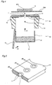
- an image forming apparatus includes a printing head unit 60, an ink cartridge 50 detachably mounted to printing head unit 60 for supplying ink into printing head unit 60, a recording medium RM, and a back electrode 14 provided over the rear surface of recording medium RM.
- Ink cartridge 50 includes a reservoir 1 for storing powdery ink IP, and a vaporizing heater 9 for heating and vaporizing powdery ink IP.
- Printing head unit 60 includes a charging electrode 10 for charging gaseous ink IPG vaporized by vaporizing heater 9, an ejection port substrate 12 having an ejection port 7 for ejecting gaseous ink IPG onto recording medium RM, a cartridge support member 13 for supporting ink cartridge 50 mounted to printing head unit 60, a buffer member 16 provided between mounted ink cartridge 50 and ejection port substrate 12, a cartridge fixing lid 15 for fixing mounted ink cartridge 50, and an electric field shutter electrode 11 provided surrounding ejection port 7 for controlling ejection of gaseous ink IPG.
- Powdery ink IP is stored within reservoir 1.
- Vaporizing heater 9 for vaporizing powdery ink IP is provided at the lower portion of reservoir 1.
- the top surface of reservoir 1 is closed up by a seal (not shown), and the seal is removed for use of the ink cartridge to open the top surface.
- ink cartridge 50 is mounted to printing head unit 60 by moving it from the lower portion of printing head unit 60 along cartridge support member 13 in the direction of the arrow Al. Then, cartridge fixing lid 15 is moved in the direction of the arrow B1 to lid printing head unit 60, whereby the top surface of reservoir 1 comes into contact with ejection port substrate 12 through buffer member 16 made of a conductive rubber material.
- a wire having a diameter in the range from 50 to 80 ⁇ m is provided as charging electrode 10 for charging gaseous ink IPG.
- Ejection port 7 for ejecting gaseous ink IPG is formed in ejection port substrate 12.
- Electric field shutter electrode 11 for controlling the ejection amount of gaseous ink IPG is provided at both surfaces of ejection port substrate 12, surrounding ejection port 7.
- the diameter of ejection port 7 corresponds to the printing density. If the recording density is 150 dpi, for example, the diameter is set to 300 ⁇ m.
- Recording medium RM is placed over electric field shutter electrode 11, and an electrode plate is provided over recording medium RM as back electrode 14.
- powdery ink IP is heated to a temperature in the range from 150 to 200°C and vaporized by vaporizing heater 9.
- Coloring materials for the ink are the same as those previously described in conjunction with the image forming apparatus of Fig. 3. Therefore, detailed description thereof will not be repeated herein.
- ink cartridge 50 is provided with vaporizing heater 9 for vaporizing powdery ink IP. Therefore, even if the residue resulting from vaporization of powdery ink IP adheres to vaporizing heater 9, vaporizing heater 9 can be replaced with a new one by exchanging ink cartridge 50. Accordingly, the image forming apparatus need not be repaired for deterioration of vaporizing heater 9.
- powdery ink IP is vaporized inside ink cartridge 50, powdery ink IP need not be transported.
- Charge electrode 10 should be placed at such a position that it is not in contact with powdery ink IP within reservoir 1 when ink cartridge 50 is mounted. Therefore, powdery ink IP is supplied to reservoir 1 to such an extent that powdery ink IP is not in contact with charging electrode 10 when ink cartridge 50 is mounted.
- a seal is applied to the top surface of ink cartridge 50 in order to prevent leakage of ink at the time when ink cartridge 50 is not mounted
- the present invention is not limited to this and may seal reservoir 1 by means of a lid.
- used ink cartridge 50 can be reused.
- such a shutter mechanism that opens a shutter when ink cartridge 50 is mounted may be provided at the top surface of ink cartridge 50, whereby the operativity of the ink cartridge is improved.
- the image forming apparatus includes a printing head unit 60A, an ink cartridge 50A detachably mounted to printing head unit 60A, a recording medium RM, and a back electrode 14.
- Ink cartridge 50A includes a reservoir 1A for storing powdery ink IP, a thermal conductive plate 17 for conducting heat of a heater 19 which will be described later to powdery ink IP to vaporize it, and an ink shutter 18 for opening and closing a supply port 3 formed in reservoir 1A.
- Printing head unit 60A includes the above-mentioned heater 19 for heating powdery ink IP stored in ink cartridge 50A, a charging electrode 10, an ejection port substrate 12A having an ejection port 7A, a cartridge support member 13A, a buffer member 16A, and an electric field shutter electrode 32 provided surrounding ejection port 7A for controlling ejection of vaporized ink IPG.
- Cartridge support member 13A has a projection 31.
- Electric field shutter electrode 32 includes an electric field shutter electrode portion 32A and a plurality of electric field shutter electrode portions 32B.
- Powdery ink IP is stored in reservoir 1A.
- Thermal conductive plate 17 for vaporizing powdery ink IP is provided in the lower portion of reservoir 1A.
- a slit serving as supply port 3 for supplying gaseous ink IPG is formed in the top surface of reservoir 1A, and ink shutter 18 is provided to open and close this supply port 3.
- ink cartridge 50A is mounted to printing head unit 60A by moving it from the side portion of printing head unit 60A along cartridge support member 13A in the direction of the arrow A2.
- ink shutter 18 is pushed by projection 31 of cartridge support member 13A in such a direction that supply port 3 is opened, and the top surface of reservoir 1A comes in contact with cartridge support member 13A through buffer member 16A made of a conductive rubber material.
- thermal conductive plate 17 of reservoir 1A is placed on heater 19, whereby heat generated by heater 19 is conducted to ink cartridge 50A.
- a wire having a diameter in the range from 50 to 80 ⁇ m which serves as charging electrode 10 for charging vaporized ink IPG is provided between ejection port substrate 12A of printing head unit 60A and ink cartridge 50A.
- a slit serving as ejection port 7A for ejecting vaporized ink IPG is formed in ejection port substrate 12A.
- electric field shutter electrode 32 is provided along both longer sides of ejection port 7A.
- the length of ejection port 7A corresponds to the printing width. If the recording density is 150 dpi, for example, the width of the slit is set to 200 ⁇ m.
- Electric field shutter electrode 32A being grounded is provided on one side of ejection port 7A, while a plurality of electric field shutter electrodes 32B are provided on the other side thereof to have a comb shape with a space of 169 ⁇ m therebetween corresponding to the recording density.
- Recording medium RM is placed over electric field shutter electrode 32, and back electrode 14 is provided over recording medium RM.
- heat generated by heater 19 is conducted through thermal conductive plate 17 to heat powdery ink IP to a temperature in the range from 150 to 200°C to gaseous ink.
- Coloring materials for the ink are the same as those in the first embodiment, and description thereof will not be repeated herein.
- Powdery ink IP is vaporized to gaseous ink IPG.
- a voltage of +2kV is applied to charging electrode 10, whereby corona discharge occurs toward thermal conductive plate 17 connected to the ground, and gaseous ink IPG is positively charged.
- a voltage of -0.5kV is applied to back electrode 14 provided over the rear surface of the printing surface of recording medium RM, whereby gaseous ink IPG thus charged is attracted toward recording medium RM.
- a voltage of 500V is applied to electric field shutter electrode 32 with ejection port 7A therebetween, based on a signal corresponding to image data to be recorded.
- gaseous ink IPG is controlled to pass or to be prevented from passing through ejection port 7A. Gaseous ink IPG having passed through ejection port 7A is attracted toward back electrode 14 to adhere to recording medium RM.
- heat generated by heater 19 provided in printing head unit 60A is conducted by thermal conductive plate 17 to heat powdery ink IP, whereby the structure of the ink cartridge can be simplified.
- the present invention is not limited to this, and may use a seal or a lid as described in the first embodiment.
- the shutter structure as well, the present invention is not limited to the above-described structure.
- ejection port 7A has a slit-shape
- the present invention is not limited to this, and the ejection port may have a dot-shape as shown in the first embodiment.
- the electric field shutter electrode also has a shape as shown in the first embodiment.
- heater 19 of printing head unit 60A is pushed upward by a spring or the like, contact between thermal conductive plate 17 and heater 19 is ensured and contact between the upper portion of reservoir 1A and buffer member 16A is improved, thereby preventing leakage of ink at the time of printing.
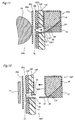
- the image forming apparatus according to the third embodiment includes a printing head unit 60B, an ink cartridge 50B detachably mounted to printing head unit 60B, a recording medium RM, and a back electrode 14.
- Ink cartridge 50B includes a reservoir 1B for storing powdery ink IP, a vaporizing heater 9 for vaporizing powdery ink IP, and a charging electrode 20 for charging vaporized ink IPG.
- Reservoir 1B has a supply port 3B and a location hole 34.
- Printing head unit 60B includes a heater power supply unit 21 for supplying power to vaporizing heater 9, an ejection port substrate 12B having an ejection port 7B, a cartridge support member 13B, a buffer member 16B, and an electric field shutter electrode 11 provided surrounding ejection port 7B for controlling ejection of vaporized ink IPG.
- Cartridge support member 13B includes a location pin 33 for locating ink cartridge 50B, and a power supply unit 22 for supplying power to charging electrode 20.
- Powdery ink IP is stored in reservoir 1B.
- Vaporizing heater 9 for vaporizing powdery ink IP is provided in the lower portion of reservoir 1B.
- a needle electrode serving as charging electrode 20 is provided at such a position that it is not in contact with powdery ink IP in the upper half of the cartridge.
- a slit serving as supply port 3B for supplying gaseous ink IPG is formed in the top surface of reservoir 1B.
- ink cartridge 50B is mounted to printing head unit 60B by moving it from the side portion of printing head unit 60B along cartridge support member 13B in the direction of the arrow A3.
- heater power supply unit 21 and power supply unit 22 of printing head unit 60B are respectively located to abut against vaporizing heater 9 and charging electrode 20, by location pin 33 of cartridge support member 13B and location hole 34 at the side surface of reservoir 1B.
- the top surface of reservoir 1B comes in contact with ejection port substrate 12B through buffer member 16B made of a conductive rubber material.
- vaporizing heater 9 operates in response to voltage application from heater power supply unit 21, and heats powdery ink IP to a temperature in the range from 150 to 200°C to vaporize it.
- Coloring materials for the ink are the same as those in the first embodiment, and description thereof will now be repeated herein.
- a voltage of -0.5kV is applied to back electrode 14 provided over the rear surface of the printing surface of recording medium RM, whereby gaseous ink IPG thus charged is attracted toward recording medium RM.
- a voltage of 400V is applied to electric field shutter electrode 11 based on a signal corresponding to image data to be recorded.
- gaseous ink IPG is controlled to pass or to be prevented from passing through electric field shutter electrode 11.
- Gaseous ink IPG having passed through electric field shutter electrode 11 is attracted toward back electrode 14 to adhere to recording medium RM.
- charging electrode 20 is provided inside ink cartridge 50B, charging electrode 20 is also replaced with a new one by exchanging ink cartridge 50B. Accordingly, the image forming apparatus need not be repaired for degradation of charging electrode 20 resulting from adhesion of gaseous ink IPG or the like.
- a shutter, a seal or the like may be provided as in the first embodiment.
- ejection port 7B may have a slit-shape.
- the electric field shutter electrode has the same shape as that in the second embodiment.
- a guide member may be provided in printing head unit 60B to mount ink cartridge 50B to printing head unit 60B by guiding reservoir 1B along the guide member.
- the structure in which the heater power supply unit in the printing head unit is pushed upward by a spring or the like may be employed, and the present invention may employ another structure as long as the structure ensures the contact between heater power supply unit 21 and vaporizing heater 9 and the contact between power supply unit 22 and charging electrode 20.
- the image forming apparatus according to the fourth embodiment includes a printing head unit 60C, an ink cartridge 50C detachably mounted to printing head unit 60C, a recording medium RM (not shown), and a back electrode 14 (not shown).
- Ink cartridge 50C includes a reservoir 1C for storing powdery ink IP, and a thermal conductive plate 17 for conducting heat generated by a heater 19 which will be described later to powdery ink IP to vaporize it.
- Printing head unit 60C includes the above-mentioned heater 19 for heating powdery ink IP stored in ink cartridge 1C, a charging electrode 10, an ejection port substrate 12C connected to the charging electrode and having an ejection port 7C, a cartridge support member 13C, a buffer member 16C, and an electric field shutter electrode 11 provided surrounding ejection port 7C for controlling ejection of vaporized ink IPG.
- Powdery ink IP is stored in reservoir 1C.
- Thermal conductive plate 17 for conducting heat generated by heater 19 to vaporize powdery ink IP is provided in the lower portion of reservoir 1C.
- a slit serving as supply port 3C for supplying vaporized ink IPG is formed in the top surface of reservoir 1C.
- Ejection port 7C for ejecting vaporized ink IPG is formed in ejection port substrate 12C, and electric field shutter electrode 11 for controlling ejection of vaporized ink IPG is provided at both surfaces of ejection port substrate 12C, surrounding ejection port 7C.
- Ejection port substrate 12C and charging electrode 10 connected thereto can pivot in the direction shown by the arrow B4.
- ejection port substrate 12C and charging electrode 10 are first lifted upward, ink cartridge 50C is mounted to printing head unit 60C by moving it from the side portion of printing head unit 60C along cartridge support member 13C in the direction of the arrow A4, and thereafter ejection port substrate 12C and charging electrode 10 are put downward, thereby fixing reservoir 1C. At this time, the top surface of reservoir 1C comes in contact with ejection port substrate 12C through buffer member 16C made of a conductive rubber material.
- charging electrode 10 is inserted into ink cartridge 50C. Therefore, the distance between charging electrode 10 and an opposing electrode (thermal conductive plate 17 of ink cartridge 50C) is reduced, whereby a charging voltage can be reduced.
- Ejection port substrate 12C and charging electrode 10 can move in the range from the position where ejection port substrate 12C fixes ink cartridge 50C to the position where ejection port substrate 12C is not in contact with back electrode 14. If back electrode 14 can be moved prior to mounting/removal of ink cartridge 50C, the movable range of ejection port substrate 12C and charging electrode 10 would be increased. In this case, ejection port substrate 12C can be opened largely. Accordingly, ink cartridge 50C can be readily mounted and removed. In addition, work required at the time of cleaning charging electrode 10 is simplified. Either a wire electrode or a needle electrode may be used as charging electrode 10. Since a needle electrode has a larger diameter than that of a wire electrode, the size of supply port 3C in ink cartridge 50C will be accordingly increased. Therefore, it is desirable to use a needle electrode.
- ejection port 7C has a dot-shape
- it may have a slit-shape, and in this case the electric field shutter electrode has the same shape as that in the second embodiment.
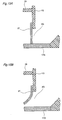
- the image forming apparatus according to the fifth embodiment includes a printing head unit 60D, an ink cartridge 50D, a recording medium RM, and a back electrode 14.
- Ink cartridge 50D includes a reservoir 1D.
- reservoir 1D has a supply port 3D for supplying ink.
- Printing head unit 60D includes a heater 19, a charging electrode 10, an ejection port substrate 12D having an ejection port 7D, a cartridge support member 13D, a buffer member 16D, and an electric field shutter electrode 11.
- Cartridge support member 13D includes a sensor 23.
- Powdery ink IP is stored in ink cartridge 50D.
- Supply port 3D is formed in the lower portion of a side surface of ink cartridge 50D, and a bottom surface portion of ink cartridge 50D is tilted such that supply port 3D is located on the downstream side.
- Supply port 3D is closed up by a seal (not shown), and the seal is removed for use of the ink cartridge to open supply port 3D.
- ink cartridge 50D is mounted to printing head unit 60D in the direction of the arrow B5 with the portion in the vicinity of supply port 3D in ink cartridge 50D being caught by a projection provided near heater 19 of printing head unit 60D.
- the top surface of ink cartridge 50D comes in contact with ejection port substrate 12D through buffer member 16D made of a conductive rubber material.
- a wire having a diameter in the range from 50 to 80 ⁇ m which serves as charging electrode 10 for charging vaporized ink IPG is provided in printing head unit 60D.
- Ejection port 7D for ejecting vaporized ink IPG is formed in ejection port substrate 12.
- Electric field shutter electrode 11 for controlling ejection of vaporized ink IPG is provided at both surfaces of ejection port substrate 12D, surrounding ejection port 7D.
- Recording medium RM is placed over electric field shutter electrode 11, and back electrode 14 is placed over recording medium RM.
- powdery ink IP supplied from supply port 3D of ink cartridge 50D onto heater 19 is heated by heater 19 to a temperature in the range from 150 to 200°C.
- Coloring materials for the ink are the same as those in the first embodiment, and description thereof will not be repeated herein.
- a voltage of +2kV is applied to charging electrode 10, whereby corona discharge occurs toward heater 19 connected to the ground, and gaseous ink IPG is positively charged.
- a voltage of -0.5kV is applied to back electrode 14, whereby gaseous ink IPG thus charged is attracted toward recording medium RM.
- a voltage of 400V is applied to electric field shutter electrode 11 based on a signal corresponding to image data to be recorded.
- gaseous ink IPG is controlled to pass or to be prevented from passing through electric field shutter electrode 11.
- Gaseous ink IPG having passed through electric field shutter electrode 11 is attracted toward back electrode 14 to adhere to recording medium RM.
- Presence/absence of powdery ink IP in ink cartridge 50D can be detected by ink amount sensor 23 provided in cartridge support member 13D.
- powdery ink IP is successively supplied into printing head 60D due to the gravity. Accordingly, efficient vaporization of ink can be achieved.
- sensor 23 for detecting the amount of ink is provided in the vicinity of supply port 3D, presence/absence of ink can be readily known without complicating the structure of the apparatus.
- Buffer member 16D may be provided between ink cartridge 50D being mounted and ejection port substrate 12D.
- the structure of printing head unit 60D is somewhat complicated, but leakage of ink through the gap between ejection port substrate 12D and ink cartridge 50D can be prevented and the operativity for placement of ink cartridge 50D can be improved.
- the image forming apparatus according to the sixth embodiment includes a printing head unit 60E, an ink cartridge 50E, a recording medium RM, and a back electrode 24.
- Ink cartridge 50E includes a reservoir lE, an ink sensor 23, and a vaporizing heater 9E.
- Reservoir 1E has a supply port 3E for supplying ink.
- Printing head unit 60E includes a charging electrode 10, an ejection port substrate 12E having an ejection port 7E, a cartridge support member 13E, a buffer member 16E, a thermal conductive plate 17E, and an electric field shutter electrode 11.
- Powdery ink IP is stored in reservoir 1E.
- Supply port 3E is formed in the lower portion of a side surface of ink cartridge 50E.
- a bottom surface portion of ink cartridge 50E is tilted downward to supply port 3E, and vaporizing heater 9E for vaporizing powdery ink IP is provided at the bottom surface portion.
- Supply port 3E in ink cartridge 50E is closed up by a seal (not shown), and the seal is removed for use of the ink cartridge to open supply port 3E.
- the surface of ink cartridge 50E on the side of supply port 3E comes in contact with cartridge support member 13E through buffer member 16E made of a conductive rubber material.
- a wire having a diameter in the range from 50 to 80 ⁇ m is provided in printing head unit 60E as charging electrode 10 for charging gaseous ink IPG.
- Ejection port 7E for ejecting gaseous ink IPG is formed in ejection port substrate 12E.
- Electric field shutter electrode 11 for controlling ejection of gaseous ink IPG is provided at both surfaces of ejection port substrate 12E, surrounding ejection port 7E.
- vaporizing heater 9E in ink cartridge 50E heats powdery ink IP to a temperature in the range from 150 to 200°C to vaporize it.
- Coloring materials for the ink are the same as those in the first embodiment, and description thereof will not be repeated herein.
- thermal conductive plate 17E for conducting heat generated by vaporizing heater 9E.
- a voltage of +2kV is applied to charging electrode 10, whereby corona discharge occurs toward thermal conductive plate 17E connected to the ground, and gaseous ink IPG is positively charged.
- a voltage of -0.5kV is applied to back electrode 24 provided on the rear surface of the printing surface of recording medium RM, whereby gaseous ink IPG is attracted toward recording medium RM.
- a voltage of 400V is applied to electric field shutter electrode 11 based on a signal corresponding to image data to be recorded.
- gaseous ink IPG is controlled to pass or to be prevented from passing through electric field shutter electrode 11.
- Gaseous ink IPG having passed through electric field shutter electrode 11 is attracted toward back electrode 14 to adhere to recording medium RM. Presence/absence of powdery ink IP in reservoir 1E is detected by sensor 23 provided above supply port 3E in reservoir 1E.
- thermal conductive plate 17E of printing head unit 60E is provided only at the lower surface 13E1 of cartridge support member 13E
- the present invention is not limited to this, and a thermal conductive plate may be provided also at the upper surface 13E2 thereof.
- a heater may be provided at the upper surface 13E2.
- the structure of printing head unit 60E is complicated, but gaseous ink IPG can be prevented from becoming solid by cooling and thus can be prevented from adhering to the surface of cartridge support member 13E.
- an electrode plate may be used instead as in the above-described embodiments.
- the image forming apparatus according to the seventh embodiment includes a printing head unit 60F, an ink cartridge 50F, a recording medium RM, and a back electrode 14.
- Ink cartridge 50F includes a reservoir 1F and a thermal conductive plate 17F.
- Reservoir 1F has a supply port 3F for supplying ink.
- Ink cartridge 50F further includes a film 26 for opening and closing supply port 3F.
- Printing head unit 60F includes a heater 19, a charging electrode 20, an ejection port substrate 12F having an ejection port 7F, a cartridge support member 13F, a buffer member 16F, and an electric field shutter electrode 11.
- Cartridge support member 13F has a projection 25.
- Powdery ink IP is stored in reservoir 1F.
- Supply port 3F is formed in the lower portion of a side surface of reservoir lF, and a bottom surface portion of reservoir 1F is tilted such that supply port 3F is located on the downstream side, and protrudes with respect to the side surface 50F1 having supply port 3F.
- Thermal conductive plate 17F for vaporizing powdery ink IP is provided extending from the protruding portion to a part of the slope.
- Supply port 3F of ink cartridge 50F is closed up with an elastic film 26 which is applied in a cantilever manner on the side of the inner surface of ink cartridge 50F.
- surface 50F1 of ink cartridge 50F on the side of supply port 3F comes in contact with cartridge support member 13F through buffer member 16F made of a conductive rubber material.
- Projection 25 of cartridge support member 13F pushes film 26 of ink cartridge 50F into reservoir 1F, whereby supply port 3F is opened.
- a needle electrode serving as charging electrode 20 for charging vaporized ink IPG is provided in printing head unit 60F.
- Ejection port 7F for ejecting vaporized ink IPG is formed in ejection port substrate 12F.
- Electric field shutter electrode 11 for controlling ejection of vaporized ink IPG is provided at both surfaces of ejection port substrate 12F, surrounding ejection port 7F.
- thermal conductive plate 17F protrudes from supply port 3F and powdery ink IP is vaporized at the protruding portion, whereby vaporized ink IPG can be prevented from entering reservoir 1F.
- film 26 serving as shutter is provided at supply port 3F and projection 25 is formed in printing head unit 60F, whereby supply port 3F of ink cartridge 50F can be opened and closed with a highly simple structure.
- a piezoelectric element may be used as projection 25 of cartridge support member 13F. Operation with a piezoelectric element will now be described with reference to Figs. 13A and 13B.
- a voltage is not applied to a projection 125 of a piezoelectric element, and therefore, projection 125 does not protrude to the position of film 26 and supply port 3F is closed as shown in Fig. 13A.
- a voltage is applied to projection 125 of the piezoelectric element, whereby projection 125 extends toward film 26 to push film 26 into reservoir 1F thereby opening supply port 3F as shown in Fig. 13B.
- film 26 vibrates and powdery ink IP within reservoir 1F is quickly supplied.
- a wire electrode may be used instead as in the above-described embodiments.
- the image forming apparatus according to the eighth embodiment includes a printing head unit 60G, an ink cartridge 50G, a recording medium RM, and a back electrode 14.
- Ink cartridge 50G includes a reservoir 1G, a thermal conductive plate 17G, a charging chamber 29 having a through port 30, an ink shutter 27, a charging electrode 10, and a vibration generator 28.
- Printing head unit 60G includes a heater 19G, an ejection port substrate 12G having an ejection port 17G, a cartridge support member 13G, a buffer member 16G, and an electric field shutter electrode 11.
- Powdery ink IP is stored in reservoir 1G.
- a supply port 3G is formed in the lower portion of a side surface of ink cartridge 50G, a bottom surface portion of reservoir 1G is tilted such that supply port 3G is located on the downstream side, and charging chamber 29 is formed on the side surface having supply port 3G.
- Charging electrode 10 is provided in charging chamber 29.
- Thermal conductive plate 17G for vaporizing powdery ink IP is provided extending from charging chamber 29 to a part of the slope of reservoir 1G.
- Vibration generator 28 for facilitating supply of powdery ink IP is provided at the slope of reservoir 1G.
- Supply port 3G of reservoir 1G is closed with ink shutter 27 made of bimetal.
- Ejection port 7G for ejecting vaporized ink IPG is formed in ejection port substrate 12G.
- Electric field shutter electrode 11 for controlling ejection of vaporized ink IPG is provided at both surfaces of ejection port substrate 12G, surrounding ejection port 7G.
- thermal conductive plate 17G for conducting heat generated by heater 19G of printing head unit 60G heats powdery ink IP to a temperature in the range from 150 to 200°C to vaporize it.
- Coloring materials for the ink are the same as those in the first embodiment. Description thereof will not be repeated herein.
- a voltage of +2kV is applied to charging electrode 10, whereby corona discharge occurs toward thermal conductive plate 17G connected to the ground and gaseous ink IPG is positively charged.
- a voltage of -0.5kV is applied to back electrode 14, whereby gaseous ink IPG thus charged is attracted toward recording medium RM.
- a voltage of 400V is applied to electric field shutter electrode 11 based on a signal corresponding to image data to be recorded.
- gaseous ink IPG is controlled to pass or to be prevented from passing through electric field shutter electrode 11.
- Gaseous ink IPG having passed through electric field shutter electrode 11 is attracted toward back electrode 14 to adhere to recording medium RM.
- vibration is applied to powdery ink IP within reservoir 1G by vibration generator 28, powdery ink IP is more likely to go out from supply port 3G into charging chamber 29, preventing clogging of supply port 3G.
- Ink shutter 27 of bimetal provided at supply port 3G will now be described with reference to Figs. 15A and 15B.
- charging chamber 29 is not heated and therefore supply port 3G is closed as shown in Fig. 15A.
- ink shutter 27 made of bimetal is deformed by heat for vaporizing ink and supply port 3G is opened as shown in Fig. 15B. Since supply port 3G is opened by heat used for vaporization of ink, neither power supply nor mechanism for opening and closing the supply port is necessary, and users are prevented from inadvertently opening ink shutter 27.
- ink shutter 27 is brought into contact with thermal conductive plate 17G to be ready for voltage application and is brought out of contact at a temperature near the set preheating temperature, whereby it can be known without a temperature sensor that the preheating temperature has been reached.
- Ink shutter 27 may be made of a shape-memory alloy.
- ink shutter 27 may be made of any material as long as it is thermally deformed and has heat resistance at a temperature equal to or higher than the temperature at which ink is vaporized.
- a thermal reversible material is desirable for ink shutter 27 in view of the case where ink cartridge 50G with ink remaining therein is removed after use.
- the ink cartridge unit may have the structure shown in Fig. 16, and is not limited to the above-described example.
- the reservoir may be formed of a material having excellent thermal conductivity.
- ink can be preheated as well as the temperature thereof can be maintained, thereby achieving reduction in vaporizing time for the ink.
- vibration generator 28 used in the eighth embodiment may be used in the other embodiments.
- ink is shown to be ejected upward or laterally, the present invention is not limited to this, and ink may be ejected downward as long as it does not result in disadvantages in structure and handling of the back electrode and the recording medium.
Landscapes
- Ink Jet (AREA)
- Particle Formation And Scattering Control In Inkjet Printers (AREA)
- Electronic Switches (AREA)
Applications Claiming Priority (2)
| Application Number | Priority Date | Filing Date | Title |
|---|---|---|---|
| JP3774996A JP3148620B2 (ja) | 1996-02-26 | 1996-02-26 | 画像形成装置 |
| JP37749/96 | 1996-02-26 |
Publications (2)
| Publication Number | Publication Date |
|---|---|
| EP0791457A2 true EP0791457A2 (fr) | 1997-08-27 |
| EP0791457A3 EP0791457A3 (fr) | 1998-11-25 |
Family
ID=12506133
Family Applications (1)
| Application Number | Title | Priority Date | Filing Date |
|---|---|---|---|
| EP97301255A Withdrawn EP0791457A3 (fr) | 1996-02-26 | 1997-02-26 | Appareil de formation d'images comportant une cartouche d'encre prévenant la détérioration de l'élément chauffant par l'encre et cartouche d'encre pour cet appareil |
Country Status (2)
| Country | Link |
|---|---|
| EP (1) | EP0791457A3 (fr) |
| JP (1) | JP3148620B2 (fr) |
Cited By (1)
| Publication number | Priority date | Publication date | Assignee | Title |
|---|---|---|---|---|
| US6364462B1 (en) * | 1998-02-13 | 2002-04-02 | Sharp Kabushiki Kaisha | Image recording method and image recording apparatus permitting good picture quality to be provided |
Families Citing this family (1)
| Publication number | Priority date | Publication date | Assignee | Title |
|---|---|---|---|---|
| EP3328650B1 (fr) * | 2015-07-31 | 2025-05-07 | Kateeva, Inc. | Systèmes et procédés de distribution d'encre |
Family Cites Families (10)
| Publication number | Priority date | Publication date | Assignee | Title |
|---|---|---|---|---|
| JPS59133064A (ja) * | 1983-01-20 | 1984-07-31 | Konishiroku Photo Ind Co Ltd | 昇華性インクを用いた画像記録方法及び装置 |
| IT1179973B (it) * | 1984-02-15 | 1987-09-23 | Olivetti & Co Spa | Testina di stampa a getto selettivo di inchiostro e cartuccia di inchiostro per tale testina |
| JPS61106261A (ja) * | 1984-10-30 | 1986-05-24 | Fuji Xerox Co Ltd | インクジエツトプリンタ |
| JPS6241090A (ja) * | 1985-08-19 | 1987-02-23 | Tokyo Electric Co Ltd | 画像記録方法及びその装置 |
| JPH0712679B2 (ja) * | 1987-03-24 | 1995-02-15 | 株式会社テック | 印刷装置 |
| JPH05104724A (ja) * | 1991-10-17 | 1993-04-27 | Minolta Camera Co Ltd | インクジエツト記録装置 |
| JP3123152B2 (ja) * | 1991-11-07 | 2001-01-09 | ミノルタ株式会社 | 画像記録装置 |
| JPH089235B2 (ja) * | 1993-06-30 | 1996-01-31 | 日本電気株式会社 | インクカートリッジ及びこれを用いたプリンタ装置 |
| JPH0752423A (ja) * | 1993-08-11 | 1995-02-28 | Sony Corp | 染料気化式プリンターヘッド |
| JPH08300803A (ja) * | 1995-03-09 | 1996-11-19 | Sharp Corp | 画像記録方法および装置 |
-
1996
- 1996-02-26 JP JP3774996A patent/JP3148620B2/ja not_active Expired - Fee Related
-
1997
- 1997-02-26 EP EP97301255A patent/EP0791457A3/fr not_active Withdrawn
Cited By (1)
| Publication number | Priority date | Publication date | Assignee | Title |
|---|---|---|---|---|
| US6364462B1 (en) * | 1998-02-13 | 2002-04-02 | Sharp Kabushiki Kaisha | Image recording method and image recording apparatus permitting good picture quality to be provided |
Also Published As
| Publication number | Publication date |
|---|---|
| JPH09226146A (ja) | 1997-09-02 |
| JP3148620B2 (ja) | 2001-03-19 |
| EP0791457A3 (fr) | 1998-11-25 |
Similar Documents
| Publication | Publication Date | Title |
|---|---|---|
| EP1442892B1 (fr) | Appareil d'enregistrement à jet d'encre | |
| EP0791457A2 (fr) | Appareil de formation d'images comportant une cartouche d'encre prévenant la détérioration de l'élément chauffant par l'encre et cartouche d'encre pour cet appareil | |
| EP0774354B1 (fr) | Tête d'enregistrement à jet d'encre électrostatique et appareil d'enregistrement à jet d'encre utilisant cette tête | |
| EP0779155A2 (fr) | Tête d'impression à jet d'encre | |
| JP3102843B2 (ja) | 画像記録装置 | |
| US5881646A (en) | Method and apparatus for image recording by emitting evaporated ink onto a recording medium | |
| EP0730963A2 (fr) | Procédé d'enregistrement d'image et appareil utilisant ce procédé | |
| EP0778136A2 (fr) | Appareil d'enregistrement d'image | |
| EP0761445A2 (fr) | Dispositif d'enregistrement d'images par émission d'encre évaporée sur un support d'enregistrement | |
| JP3642617B2 (ja) | 画像記録装置 | |
| US6364462B1 (en) | Image recording method and image recording apparatus permitting good picture quality to be provided | |
| JPS63239061A (ja) | インクジェット記録装置 | |
| JP3163249B2 (ja) | 画像記録装置 | |
| EP0771653B1 (fr) | Appareil d'impression à jet d'encre électrostatique | |
| EP0780229A1 (fr) | Tête d'impression électrostatique à jet d'encre | |
| JPH10151752A (ja) | 画像形成装置 | |
| JP3115990B2 (ja) | 画像記録装置およびその制御方法 | |
| JP3720505B2 (ja) | 画像形成装置 | |
| JP2834099B2 (ja) | 静電式インクジェット記録装置 | |
| JP3182359B2 (ja) | 画像記録装置およびその制御方法 | |
| JP2001130028A (ja) | インクジェット記録装置 | |
| JPS5816854A (ja) | インクジエツト用ノズルヘツド | |
| JP3153742B2 (ja) | 画像記録方法および装置 | |
| JP2842336B2 (ja) | 静電式インクジェット記録装置 | |
| JPH08281961A (ja) | 荷電偏向型液体噴射記録装置 |
Legal Events
| Date | Code | Title | Description |
|---|---|---|---|
| PUAI | Public reference made under article 153(3) epc to a published international application that has entered the european phase |
Free format text: ORIGINAL CODE: 0009012 |
|
| AK | Designated contracting states |
Kind code of ref document: A2 Designated state(s): DE FR GB |
|
| PUAL | Search report despatched |
Free format text: ORIGINAL CODE: 0009013 |
|
| AK | Designated contracting states |
Kind code of ref document: A3 Designated state(s): DE FR GB |
|
| 17P | Request for examination filed |
Effective date: 19990202 |
|
| 17Q | First examination report despatched |
Effective date: 20000114 |
|
| STAA | Information on the status of an ep patent application or granted ep patent |
Free format text: STATUS: THE APPLICATION IS DEEMED TO BE WITHDRAWN |
|
| 18D | Application deemed to be withdrawn |
Effective date: 20010706 |