EP0791816A2 - Procédé et appareil pour l'analyse des images des particules - Google Patents
Procédé et appareil pour l'analyse des images des particules Download PDFInfo
- Publication number
- EP0791816A2 EP0791816A2 EP97102679A EP97102679A EP0791816A2 EP 0791816 A2 EP0791816 A2 EP 0791816A2 EP 97102679 A EP97102679 A EP 97102679A EP 97102679 A EP97102679 A EP 97102679A EP 0791816 A2 EP0791816 A2 EP 0791816A2
- Authority
- EP
- European Patent Office
- Prior art keywords
- particles
- particle
- image
- detection
- condition
- Prior art date
- Legal status (The legal status is an assumption and is not a legal conclusion. Google has not performed a legal analysis and makes no representation as to the accuracy of the status listed.)
- Granted
Links
Images



Classifications
-
- G—PHYSICS
- G01—MEASURING; TESTING
- G01N—INVESTIGATING OR ANALYSING MATERIALS BY DETERMINING THEIR CHEMICAL OR PHYSICAL PROPERTIES
- G01N15/00—Investigating characteristics of particles; Investigating permeability, pore-volume or surface-area of porous materials
- G01N15/10—Investigating individual particles
- G01N15/14—Optical investigation techniques, e.g. flow cytometry
- G01N15/1429—Signal processing
- G01N15/1433—Signal processing using image recognition
-
- G—PHYSICS
- G01—MEASURING; TESTING
- G01N—INVESTIGATING OR ANALYSING MATERIALS BY DETERMINING THEIR CHEMICAL OR PHYSICAL PROPERTIES
- G01N15/00—Investigating characteristics of particles; Investigating permeability, pore-volume or surface-area of porous materials
- G01N15/10—Investigating individual particles
- G01N15/14—Optical investigation techniques, e.g. flow cytometry
- G01N15/1456—Optical investigation techniques, e.g. flow cytometry without spatial resolution of the texture or inner structure of the particle, e.g. processing of pulse signals
- G01N15/1459—Optical investigation techniques, e.g. flow cytometry without spatial resolution of the texture or inner structure of the particle, e.g. processing of pulse signals the analysis being performed on a sample stream
Definitions
- the present invention relates to method and apparatus for particle image analysis, and more particularly to method and apparatus suitable for picking up and analyzing still images of particles suspended in a fluid sample flown by a flow cell.
- a sample of blood for example, is applied onto a slide glass which is then mounted on a microscope, and a microscope stage is automatically scanned and stopped at a position where particles are present to pick up a still particle image, and the particles in the sample are classified and analyzed by using feature extraction and pattern recognition method by image processing technique.
- a flow cytometer method As a particle image analysis method or a particle image analysis apparatus which does not need the preparation of the applied sample, a flow cytometer method has been known in which sample particles suspended in fluid are flown in a flow cell and they are optically analyzed. The flow cytometer method observes a strength of fluorescence or scattered light from each particle in the sample and has a processing ability of 1000 particles per second.
- particles picked up in one image which is picked up by an image pick-up unit and particles detected by a particle detection unit are correlated one to one.
- particles corresponding to the detected particles of the particles present in the image when a flash lamp light source is lit are counted from the particle detection signal, and the count is correlated to the detected particles of the particles present in the image to discriminate the particles which are not regarded as the detected particles from the detected particles.
- a complicated circuit configuration is required.
- a particle image analysis method for picking up still images of particles as the particles flowing in a flow cell are detected and analyzing the picked-up still images of the particles comprising a step of flowing fluid having particles suspended therein to the flow cell, a step of counting the number of still images of particles having lager sizes than a predetermined size, of the still images of particles obtained for the fluid, a step of counting the number of particles having larger detection signals than a predetermined level, of the particles detected for the fluid, a step of calculating the anticipated number of particles to be image-processed based on the counted number of particles; and a step of comparing the counted number of still images and the calculated number of particles.
- a particle image analysis apparatus having particle detection means for detecting particles in a sample flowing in a flow cell, a light source for emitting a pulsive light in response to the detection of the particle, means for picking up still images of the particles in response to light emission and means for analyzing the picked-up still images of particles; comprising detection condition adjusting unit for receiving a particle detection signal from said particle detection means, characterized in that said detection condition adjusting unit including a) size setting means for setting a lower limit of a size of particle to be image-processed, b) count means for counting the number of still images of particles having larger sizes than the setting set by said size setting means, c) detection signal setting means for setting a magnitude of a signal to be limited, of the output signal from said particle detection means, d) signal count means for counting the number of signals larger than the setting set by said detection signal setting means, e) calculation means for calculating the anticipated number of particles to be image-processed based on information from said signal count means,
- An affect of a frequency characteristic of a particle detection unit in a particle image analysis apparatus having a flow cell varies from apparatus to apparatus.
- a semiconductor laser which is commonly used as a laser light source of the particle detection unit
- a spread of a laser beam includes a large variation and a beam spot size after focused by a lens varies from element to element.
- a detection condition of the particle detection unit varies from apparatus to apparatus.
- the anticipated number of image-processed particles is determined based on the counted number of particles with consideration of a measurement condition. Since a calculation formula to acquire the anticipated number of image-processed particles may be changed by the measurement condition, the anticipated number of image-processed particles may be determined to cope with the change of the measurement condition.
- the measurement condition may include a sample amount, a flow rate of sample fluid flow, a measurement time and a particle image pick-up condition, and once the condition is determined, the number of image particles may be statistically anticipated.
- a particle disposal condition is set by an operator based on a particle size in a flow direction of the particle image of interest.
- the particle detection condition is adjusted by changing a particle detection level of the particle detection unit and a pulse width of a particle detection signal. In this manner, the adjustment which considers the variation of the laser output and the variation of the adjustment condition of the optical system which influence to the signal condition of the particle detection unit is attained.
- the particle detection unit For the number of times of pulsive turn-on of the flash lamp, the particle detection unit is adjusted based on the calculated value and the actual number of times of turn-on. Thus, the failure of turn-on of the lamp and the malfunction of the control circuit for the lamp turn-on circuit can be checked.
- the anticipated number of image-processed particles is a mean value of multiple measurements of the same fluid sample.
- an adjustment condition with a small statistical variation factor may be set.
- the anticipated number of image-processed particles may be a mean value of measurements of different fluid samples.
- the adjustment condition of the particle detection unit may be grasped without considering a difference between particle densities. This is attained because the evaluation may be made by a ratio of the calculated value and the actual number of image processed particles.
- Parameters used in the adjustment are measured before the start of the measurement of the fluid sample.
- the apparatus condition is grasped based on the measurement result and correction data for the particle analysis is obtained.
- the correction of data due to the mismatching between the sample fluid flow and the image pick-up view field can be made.
- the parameters used in the adjustment may be measured during the measurement of the actual fluid sample. Whether the operation condition of the apparatus is normal or not is monitored based on the measurement result. In this manner, the adjustment condition and the operation condition of the particle detection unit in the course of particle analysis can be grasped.
- the adjustment is made for each measurement mode. In this manner, the analysis precision of the overall particle image processing may be enhanced.
- Particles in the flow cell which passed through the particle detection area are detected, and after a predetermined time period when the detected particles reach a predetermined position in the still image pick-up area, the flash lamp is lit to pick up the still image of the particles.
- one picked-up still particle image includes small particles other than the particles detected by the particle detection unit. This phenomenon is prominent as the particle detection signal level is higher. Thus, a method for discriminating the particles to be detected from the picked-up particle image is necessary.
- particles having a signal pulse width larger than a predetermined level, of the particles which exceed the signal level of the particle detection signal are regarded as the particle detection signals.
- This pulse width corresponds to a time during which the measured particles pass through the particle detection unit and is proportional to a size of the passed particle.
- the number of anticipated particle images is calculated based on the total number of passed particles detected by the particle detection unit and as many particles as the anticipated number of particles are used in the descending size order from the image-processed particle image.
- This method is simple in processing and includes less time restriction but the particle feature parameters must be stored until the measurement is completed.
- a large image memory is required for the measurement object which needs to store the particle image.
- particles in the image which have smaller particle sizes than a predetermined size are disposed in a stage of processing one frame of image.
- the present invention conforms to the setting of the particle disposal size and the adjustment of the particle detection unit.
- the particle disposal size is set rather small, the number of particle images to be classified increases, the number of particle feature parameters increases and a larger image memory is required. In this case, since particles other than the detected particles are introduced, the particle classification precision may be affected.
- the particle detection condition and the particle disposal size for disposing the particles in the image must be adjusted to a proper condition. Further, the particle detection condition must be set and adjusted by considering the affect of the spot size of the laser to be used, the affect of the frequency characteristic of the particle detection circuit and the affect of the scattering characteristic of the scattered particles. The affects are more prominent as the particle size is smaller or the flow rate of the flow system is faster.
- the measured pulse width changes with the magnitude of the particle detection signal because the signal amplitude is not normalized, and the variations of the laser output of the particle detection unit, the sensitivity of the detection unit and the optical system adjustment occurs for each apparatus.
- the variation factors of the pulse width are considered, it cannot be said that the particle detection operation is constant. Under such a condition, the blocked-out value of the particle size feature amount obtained from the particle image picked up for each apparatus and the pulse width detection value determined by the particle detection unit do not correlate one to one.
- the adjustment of the particle detection unit for each apparatus is not sufficient. Further, whenever the laser is exchanged or the optical system is readjusted, it is necessary to adjust the particle detection condition of the particle detection unit. A method for correlating the detected particles and the image-processed particles without need for substantially considering the complicated adjustment operation is needed.
- the present invention adopts the following method to solve the problems in the particle detection unit and in adjusting the particle disposal size in the image processing.
- the same particle detection unit as that described above is presumed. Namely, the light scatter from the particles passed through the particle detection unit is detected by the optical detector, and only those particles having pulse widths not smaller than a predetermined width and particle sizes not smaller than a designated size are selected as the particles detected by the particle detection unit. The total number of detected particles passed during the measurement time are counted and it is set as the total number of detected particles.
- the flash lamp light source is lit in response to the detection of the particles to pick up a still image of the detected particles and all particles in the image are image-processed, the particle features necessary for the particle classification are extracted, and the particle classification is conducted.
- the feature extraction and the particle classification processes are conducted for all image particles picked up during the measurement time.
- the step to dispose, without image processing, the particles of small sizes which are not necessary for the particle classification is added.
- the particle sizes disposed by this step is hereinafter referred to as a particle disposal size.
- the anticipated number of detected image particles in the particle still image by the turn-on of the flash lamp during the measurement time is calculated from the total number of detected particles passed during the measurement time in the particle detection unit.
- the number of detected image particles is calculated based on the particle density in the sample, the measurement time and the image pick-up condition of the TV camera.
- Nf Tm/Tf .
- ⁇ represents a ratio of the number of frames picked up by the particle detection under the actual sampling condition to Nf, and the content of ⁇ varies with the measurement condition.
- Nf ⁇ corresponds to the number of anticipated frames which actually picked up the particle images.
- the content of ⁇ ... ⁇ represents the anticipated mean number of particles including the detected particles present in the image read area, where ⁇ represents the mean number of particles present in a volume Vg corresponding to the volume of the image read area, h represents a value between 0 and 1 which is determined by a particular point in the image read area to turn on the flash lamp by the particle detection, and it is normally set to a value close to 1, and ⁇ is expressed by a formula (2).
- the formula for ⁇ varies with the particle density, the measurement time and the condition of the TV camera image pick-up unit.
- the anticipated number of detected particles provides a relatively correct number of detected image particles although statistical variation is unavoidable.
- the value Nf ⁇ y corresponds to the mean number of times of turn-on of the flash lamp during the measurement time, that is, the mean number of frames of the TV image picked up by the particle detection. Accordingly, by substituting it by the total number of images actually image-processed, that is, the total number of frames n f ' having the particle images picked up, the process becomes simpler.
- Nf ⁇ is substituted by n f '
- the particles to be classified are determined, a lower limit of the particle sizes occupied by the particles is determined, and it is set as an upper limit of the particle size to be disposed in the image processing.
- the particle images having sizes smaller than the disposal size are not considered as the image particles to be processed. Accordingly, the particle image feature parameters and the particle images for those images are not stored.
- An appropriate particle detection condition that is, the particle detection level and the pulse width are determined and the measurement of the particles is started.
- the total number of particle signals which satisfy the above detection condition is counted in the particle detection unit.
- the total number of particles passed during the measurement time is obtained.
- the anticipated number of images Ng which would have been processed during the measurement time as the particle images is calculated by using the formulas (1) and (3) or the formula (4).
- the anticipated number of images Ng is compared with the total number of particles Ng' which are actually image-processed. If Ng' is larger than Ng, the particle detection condition is set severer to change the particle detection condition not to detect particles having small signals. On the contrary, if Ng' is smaller than Ng, the particle detection condition is set less sever to change the condition to detect more particles by the particle detection unit.
- the adjusted condition is to set the detection level of the particle detection unit and the detected pulse width such that Ng is equal to Ng', that is, to set such that Ng'/Ng is equal to 1.
- Ng'/Ng since the statistical variation is unavoidable in an actual case, it is preferable to set Ng'/Ng to be somewhat larger than 1. It is safer not to determine by one measurement result but determine based on a mean value of a plurality of times of measurements. So long as the determination is made based on Ng'/Ng, the sample of the multiple measurements need not be the same sample.
- the particle detection condition of the particle detection unit may be set first and the adjustment work may be conducted for the particle disposal size in the image processing. It is appropriate from the detection condition of the particle detection unit to consider the particle disposal size based on the length along the flow direction of the particles.
- the above adjustment work is needed for each measurement mode. Since the difference in the measurement modes is usually the difference in the particles to be measured, the particle detection conditions are usually different.
- the operation condition of the flow type image analysis apparatus may be checked by using various parameters used in the adjustment means.
- the number of image-processed particles anticipated from the total number of passed particles can be calculated from the count of the total number of particles passed through the particle detection unit during the measurement time, this value is compared with the total number of image-processed particle images. If the anticipated number of image particles by the calculation is larger than the number of particles actually image-processed, it is okay. However, if the number of particles actually image-processed is smaller, it is determined whether it is due to the statistical error or a problem in the apparatus. If no problem is found, the number of particles is corrected based on the normal classification result and the classification ration. If a problem is involved, the correction of the number of particles is stopped and the presence of problem is noticed to the operator.
- This condition may be caused by the reduction of the output of the particle detection laser, a trouble in the particle detection unit, misadjustment and the failure of turn-on of the flash lamp.
- the above parameters may be checked as means to check whether the apparatus operates normally and as readjustment means to grasp the adjustment condition.
- the ratio of the number of times of actual turn-on of the flash lamp to the number of times of the pulsive turn-on anticipated by the formula (6) to determine the condition of the control unit for the lamp and the lifetime of the lamp Namely, it may be conducted for the total number of frames which pick up the particle images during the measurement time.
- the anticipated number of image-processed frames may be calculated from the formula (6) based on the count of the total number of frames which pick up the particle images during the measurement time, and this value is compared with the number of image frames actually processed to determine the condition of the apparatus. A deviation from the calculated value may occur due to mistiming of the control unit for the turn-on of the flash lamp.
- the above check operation of the apparatus may be conducted by measuring the parameters for each measurement sample during the measurement of the actual samples by the flow type particle image analysis apparatus to monitor whether the operation condition of the apparatus is normal or not. If the statistical variation is large, a mean value for a plurality of samples may be calculated to examine the adjustment condition of the apparatus. In this case, the measurement samples need not be of the same type or of the same particle density.
- numeral 100 denotes a flow cell
- numeral 101 denotes an image pick-up unit
- numeral 102 denotes a particle detection unit
- numeral 103 denotes a particle analysis unit
- numeral 1 denotes a flash lamp
- numeral 1a denotes a flash lamp drive circuit
- numeral 2 denotes a field lens
- numeral 3 denotes a microscope condenser lens
- numeral 5 denotes a microscope object lens
- numeral 6 denotes a focusing position
- numeral 7 denotes a projection lens
- numeral 8 denotes a TV camera
- numeral 11 denotes a view field iris
- numeral 12 denotes an aperture iris
- numeral 15 denotes a semiconductor laser
- numeral 16 denotes a collimator lens
- numeral 17 denotes a cylindrical lens
- numeral 18 denotes a reflection mirror
- numeral 19 denotes a microreflection mirror
- numeral 20 de
- the flow type particle image analysis apparatus in accordance with the embodiment of Fig. 1 comprises the flow cell 100 to which sample fluid having particles suspended therein is supplied, the image pick-up means 101 for picking up the image of the sample fluid in the flow cell 100, the particle detection means 102 for detecting the particles form the picked-up image and the particle analysis means 103 for analyzing the detected particles.
- the flow cell 100 is supplied with sheath fluid together with the sample fluid so that the sample fluid forms a flow encompassed by the sheath fluid.
- the sample fluid flow 110 becomes a stable steady flow, a so-called sheath flow having a flat sectional shape perpendicularly to a microscope optical axis 9 (to be described later) of the image pick-up means 101 (to be described later), and it flows from the top to the bottom of the drawing at the center of the flow cell 100.
- a flow rate of the sample fluid flow 110 is controlled by the central control unit 29 (to be described later).
- the image pick-up unit 101 functions as the microscope and comprises the flash lamp 1 which serves as the pulse light source, the flash lamp drive circuit 1a for lighting the flash lamp 1, the field lens for collimating the pulse light beam from the flash lamp 1, the microscope condenser lens 3 for focusing the collimated pulse light beam 10 from the field lens 2 to the sample fluid flow 110 in the flow cell 100, the microscope object lens 5 for condensing the pulse light beam irradiated to the sample fluid flow 110 in the flow cell 100 and focusing it to the focusing position 6, the TV camera 8 for converting the particle images at the focusing position 6 projected through the projection lens 7 to an image data signal which is a read electrical signal by a so-called interlace method, the view field iris 11 and the aperture iris 12 for limiting the width of the pulse light beam 10.
- the TV camera a CCD camera which exhibits a low degree of residual image is commonly used.
- the particle detection unit 102 comprises the semiconductor laser 15 which is the detection light source for emitting a laser beam as a detection light, the collimator lens 16 for collimating the laser beam from the semiconductor laser 15 to the collimated laser beam 14, the cylindrical lens 17 for focusing only one direction of the laser light beam 14 from the collimator lens 16, the reflection mirror 18 for reflecting the laser light beam 14 from the cylindrical lens 17, and the micro-reflection mirror 19 disposed between the microscope condenser lens 3 and the flow cell 100 for guiding the laser light beam 14 from the reflection mirror 18 to the neighborhood of the upstream of the image read area on the sample fluid flow 110.
- the particle detection unit 102 comprises the microscope object lens 5 for condensing the scattered light of the laser light beam 14 by the particles (the microscope object lens 5 being shared with the focusing microscope object lens 5 of the image pick-up means 101), the beam splitter 20 for reflecting the scattered light condensed by the microscope object lens 5, the optical detection circuit 22 for receiving the scattered light from the beam splitter 20 through the iris 21 and outputting an electrical signal representing the intensity thereof, and the flash lamp turn-on control circuit 23 for activating the flash lamp drive circuit 1a in accordance with the electrical signal from the optical detection circuit 22.
- the particle analysis unit 103 comprises the AD converter 24 for converting the image data signal transferred from the TV camera 8 to a digital signal, the image memory 25 for storing the data based on the signal from the AD converter 24 to a predetermined address, the image processing control circuit 26 for controlling the writing and the reading of the data in the image memory, the feature extraction circuit 27 for conducting the image processing in accordance with the signal from the image memory 25 and extracting the classes and the number of particles, the identification circuit 28, the central control unit 29, the particle detection unit adjusting unit 40 for determining the number of particles in the sample fluid 110 and adjusting the particle detection unit, and the display unit 50 for displaying the number of particles and the classification which are results of the image processing.
- the central control unit 29 is constructed to control the image pick-up condition of the TV camera 8 and the condition of the flow of the sample fluid in the floe cell 100, control the image processing circuit 26, store the image process result from the identification circuit 28, exchange the data with the particle detection unit adjusting unit 40 and display the data on the display unit 50.
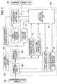
- FIG. 2 the configuration of the particle detection unit adjusting unit 40 is explained.
- the like elements to those shown in Fig. 1 are designated by the like numerals and the explanation thereof is omitted.
- numeral 44 denotes a particle detection circuit
- numeral 41 denotes a detection level setting circuit
- numeral 42 denotes a detection pulse width setting unit
- numeral 43 denotes a detected particle counter
- numeral 70 denotes a particle image count calculation unit
- numeral 71 denotes a flash lamp turn-on count calculation unit
- numeral 72 denotes a particle image count unit
- numeral 73 denotes a flash lamp turn-on count unit
- numeral 74 denotes a size disposal condition setting unit.
- the particle detection circuit 44 of the particle detection unit adjusting unit 40 detects a particle detection signal which is not smaller than a predetermined signal level, from the optical detection circuit 22.
- the particle detection level of the particle detection circuit 44 is compared with the detection condition set by the detection level setting unit 41 and the detection pulse width setting unit 42, and those signals which meet the condition are regarded as the particle detection signals.
- the detected particle counter 43 counts the number of pulses detected by the particle detection circuit 44. At the end of the measurement, the count of the detected particle counter 43 represents the total number of particles passed through the detection unit.
- the number of image-processed particles Ng which are anticipated to be image-processed during the measurement time is calculated by the particle image count calculation unit 70 and the number of times of turn-on nf which is anticipated for the turn-on of the flash lamp during the measurement time is calculated by the flash lamp turn-on count calculation unit 71.
- the number of particle images Ng' actually image-processed during the measurement time and the actual number of times of turn-on of the flash lamp nf' are set to the particle image count unit 72 and the flash lamp turn-on count unit 73 from the image processing control circuit 26 and the flash lamp turn-on control circuit 23, respectively.
- the image processing is suspended based on the condition of the size disposal condition setting unit 74 during the image processing.
- the detection unit control unit 75 controls the particle detection condition and the size disposal condition in the image processing, compares the calculation count nf and the Nf at the end of the measurement with the actual measurements nf' and Ng', and controls the overall particle detection unit adjusting unit such as the change of the particle detection condition.
- the detected particle counter 43 counts the total number of particles detected within the measurement time, this count is used to calculate the total anticipated number of particle images which are actually image-processed within the measurement time, by the particle image count calculation unit 70 by using a predetermined mathematical formula.
- the calculation formula is influenced by the measurement condition. Examples of the calculation formula is shown by formulas (1) to (4).
- the flash lamp turn-on count calculation unit 71 has a function to calculate the anticipated total number of frames picked-up by the TV camera during the measurement time. A calculation formula (6) is used.
- the operations of the image pick-up means 101 and the particle detection means 102 are first explained.
- the semiconductor laser 15 continuously oscillates and the passage of the particles in the flow of the sample fluid 110 through the detection area is always observed.
- the laser light beam 14 from the semiconductor laser 15 is converted to the collimated laser light beam by the collimator lens 16 and only one direction of the light beam 14 is focused by the cylindrical lens 17.
- the laser light beam 14 is reflected by the reflection mirror 18 and the micro-reflection mirror 19 and irradiated to the sample fluid flow 110 in the flow cell 100.
- the irradiation position is the particle detection position at which the laser light beam 14 is focused by the cylindrical lens 17, and it is the position in the neighborhood of the upstream of the image read region on the sample fluid flow 110.
- the laser light beam 14 When the particles to be analyzed traverse the laser light beam 14, the laser light beam 14 is scattered. The scattered light of the laser light beam is reflected by the beam splitter 20 and detected by the optical detection circuit 22 which converts it to an electrical signal in accordance with the strength thereof. The output of the optical detection circuit 22 is sent to the particle detection unit adjusting unit 40 which takes those signals not smaller than a predetermined level and a predetermined pulse width as the detected particles and outputs the result to the flash lamp turn-on control circuit 23. When the particle detection is made, it is assumed that the particles to be image-processed have passed and the detected signals are transmitted to the flash lamp turn-on control circuit 23. A predetermined delay time is determined by a distance between the particle detection position and the image read area and the flow rate of the sample fluid 110.
- the flash lamp drive circuit 1a When the flash lamp turn-on signal is transmitted to the flash lamp drive circuit 1a, the flash lamp drive circuit 1a turns on the flash lamp 1.
- the pulse light emitted by the flash lamp 1 travels on the microscope optical axis 9, collimated by the field lens 2, focused by the microscope condenser lens 3 and irradiated to the sample fluid flow 110 in the flow cell 100.
- the width of the pulse light beam 10 is limited by the view field iris 11 and the aperture iris 12.
- the pulse light beam irradiated by the sample fluid flow 110 in the flow cell 100 is focused by the microscope object lens 5 and focused to the focusing position 6.
- the image at the focusing position 6 is projected to the image pick-up plane of the TV camera 8 by the projection lens 7 and it is converted to the image data signal by the interlace method. In this manner, the still particle images of the particles in the sample fluid flow 110 are picked up.
- the image pick-up condition in the TV camera 8 is preset in the central control unit 29 and the image pick-up operation of the TV camera 8 is controlled by the image pick-up condition.
- the particle analysis unit 103 is now explained.
- the image data signal picked up by the TV camera 8 and converted by the interlace method is converted to the digital signal by the AD converter 24, and the resulting data is stored at a predetermined address of the image memory 25 under the control of the image processing control circuit 26.
- the data stored in the image memory 25 is read under the control of the image processing control circuit 26 and applied to the feature extraction circuit 27 and the identification circuit 28 for the image processing, and the result thereof is stored in the central control unit 29.
- the contents stored in the central control unit 29 are the particle identification feature parameters used for the particle classification and the particle classification result data.
- the classification identification processing of the particles is automatically conducted by the conventional pattern recognition process.
- the image processing result, the measurement condition and the number of images image-processed are sent from the image processing control circuit 26 to the particle detection unit adjusting unit 40.
- FIG. 3 a relation between the particle detection position and the still particle image read position in one image particle count is explained.
- An abscissa in Fig. 3 represents the sample fluid flow direction.
- Tg represents a time required for the particle to flow from an end B to an end A of the image
- Te represents a time required for the particle to flow from the flash lamp turn-on position P of the still particle image read view field to the end B
- To represents a time required for the particle form the end A of the image to the flash lamp turn-on position P
- the detection pulse signal is outputted. After the elapse of a delay time Td for the particle to reach the predetermined position in the still particle image read area after the detection pulse signal has been outputted, the flash lamp 1 is turned on.
- the turn-on condition of the flash lamp 1 is as follows:
- the flash lamp 1 After the completion of the reading of the still particle image by the particle detection of the immediately earlier cycle, namely, after the turn-on of the flash lamp 1 after the turn-on of the flash lamp 1 is inhibited and the image signal is transferred by one still particle image by two field read signals, the flash lamp 1 is again rendered to be ready to turn on. This is made by a lamp turn-on ready signal which is generated by the flash lamp control circuit 23. If the signal level of the lamp turn-on ready signal is "on”, the flash lamp 1 is ready to turn on, and if the signal level is "off", the flash lamp 1 is inhibited from the turn-on.
- the flash lamp 1 is turned on after the elapse of the time Td from the detection of the particle y, but it may be possible that particles passed before the detection of the particle y are present downstream of the flow.
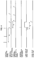
- the particle x which is present at the position of the time interval Te before the passage of the particle y may be considered since the lamp turn-on ready signal is not yet "on" during the time Te in which the sample particles flow from the point P to the end B. This appears prominently when the particle density in the sample is high. A section in which such condition occurs is shown in Fig. 4 by a hatched section of the lamp turn-on ready signal.
- the downstream particle for example, the particle x flows out of the image screen and the hatched area disappears.
- the time interval of one image particle count is the time Tg in which the particle passes through the still particle image read area.
- the detection signals are generated from three particles x, y and z.
- the particle detection delay Td signal which is delayed by the time Td after the detection of the particle is sent.
- the particle detection unit adjusting unit 40 is explained.
- the particle detection counter 43 compares the particle detection signal from the optical detection circuit 22 with the particle detection level setting unit 41 and the particle detection pulse width setting unit 42, regards the particle having a size larger than the setting conditions as the detected particle, and obtains the total number of detected particles at the end of the measurement. Based on the total number of detected particles, the number of particle images image-processed which is anticipated from the total number of passed particles and the number of times of turn-on of the flash lamp are calculated by the image-processed particle count calculation unit 70 and the flash lamp turn-on count calculation unit 71 by using the above calculation formulas. The calculated values are compared with the number of particle images actually image-processed and the actual number of times of turn-on of the flash lamp by the particle detection unit control unit 75. Specifically, the magnitudes of the calculated values and the actual values are compared.
- the calculated value is larger than the actual value, it means that the particles have been disposed in the stage of the particle image processing by some reason. Namely, in the image processing stage, it is considered that the disposal size set by the size disposal condition setting unit is larger than the particle detection condition set by the particle detection unit. On the contrary, if the calculated value is smaller than the actual value, this means that the particle disposal condition in the image processing is set to a condition to image-process even small particles.
- the particle detection condition of the particle detection unit and the size disposal condition of the particle images set by the image processing unit such that the value of the number of image-processed particles calculated from the total number of detected particles and the number of particle images actually image-processed are equal.
- the setting of the particle detection unit and the size disposal condition in the image processing is conducted in the following manner.
- the particles to be processed are determined.
- the minimum particle size of the particles is determined.
- the flow type particle image processing it is appropriate to set the size disposal condition based on the diameter in the particle flow direction.
- the detection condition of the particle detection unit is then set.
- the particle detection level is set to a level which allows the detection of only the desired particle without detecting small particles, and the particle detection pulse width is first set to an appropriate value.
- the counting of the particles and the image processing are conducted once and the anticipated number of image-processed particles is calculated by the image-processed particle count calculation unit 70 based on the count of the particle detection counter 43 by using the above calculation formula.
- the calculated value is compared with the number of particle images actually image-processed.
- the magnitude relation of the calculated value and the actual value is calculated. When the two values are equal, it means that the adjustment is in good condition for the detection condition of the particle detection unit and the size disposal condition in the image processing. If they are not equal, the particle detection pulse width setting unit 42 is changed in the direction to cause the matching and the particle sample is measured again. The above process is repeated until the calculated value and the actual value match.
- the comparison of the magnitudes and the control of the particle detection pulse width are conducted by the particle detection unit control unit 75.
- the detection pulse width of the particle detection unit is changed to adjust the particle detection unit although the same is applicable when the particle detection level is changed or both the detection pulse width and the detection level are changed.
- the counted number of still images (the number of particles to be processed) may be adjusted, or if necessary, both may be adjusted.
- the actual measurement value since the calculated value is mere anticipated mean value, the actual measurement value includes a statistical variation.
- the matching to the calculated value is preferably determined by taking the variation into consideration.
- the error may be reduced by determining based on the mean value of a plurality of times of measurement.
- the statistical variation it may be better to set the number of the particle image which is the actual measurement value to be somewhat larger than the calculated value.
- the adjustment condition of the particle detection unit can be determined without regard to the particle density. If the ratio is 1, it is in the well adjusted condition.
- the size disposal condition in the image processing is fixed and the particle detection pulse width is changed to adjust the particle detection unit.
- the object of the present invention may be attained by fixing the particle detection pulse width and changing the disposal size in the image processing.
- the anticipated number of image-processed particles is calculated from the total number of passed particles, and when the number of particle images remaining as the particle to be processed is smaller than the number of image particles anticipated from the total number of particles passed during the measurement time, the ration thereof may be calculated to produce a correction constant which is to be reflected to the particle classification and analysis result.
- a phenomenon may occur when the sample flow is deviated from the image pick-up view field of the TV camera and a portion of the particle images is not correctly picked up. It may also occur when the number of times of turn-on of the flash lamp is not proper due to a trouble in the control unit. In such cases, the number of particle images is smaller than the anticipated number of images by the calculation and the correct particle classification and analysis result is not obtained, but by calculating the reduction factor of the number of images, it may be reflected to the particle classification and analysis result.
- the operation status of the particle image analysis apparatus may be monitored based on the reduction factor of the number of images. When the factor changes beyond the statistical variation range, it is considered that an abnormal condition exists in the position variation of the sample flow or the control of the flash lamp turn-on control unit.
- the number of particle image has been noticed.
- the number of times of turn-on of the flash lamp may be noticed to adjust the particle detection unit.
- the total number of particles passed during the measurement time is counted by the detected particle counter 43, and the number of times of turn-on of the flash lamp anticipated from the total number of particles passed through the particle detection unit and the measurement condition is calculated by the flash lamp turn-on count calculation unit 71.
- the actual number of times of turn-on of the flash lamp is counted by the flash lamp turn-on count calculation unit 73.
- the anticipated number of times of turn-on of the flash lamp and the actual number of times of turn-on of the flash lamp are compared to adjust the detection condition of the particle detection unit. Further, it may be used to detect the adjustment condition of the particle detection unit and the trouble in the control unit. When the actual number of times of turn-on of the flash lamp is steadily smaller than the calculated value, the ratio thereof may be used to correct the particle analysis data.
- the mean value of a plurality of particle samples may be used for evaluation.
- the above operation may be conducted by using different particle samples.
- the operation condition of the flow type image analysis apparatus may be checked by using various parameters used in the adjustment steps.
- the parameters the number of detected particles, the calculated value of the number of image-processed particles, the actual number of image-processed particle images, the calculated value of the number of times of turn-on of the flash lamp, the actual number of times of turn-on of the flash lamp, and secondary parameters calculated from those values, for example, the ratio of the actual measurement value to the calculated value may be used.
- the various parameters described above may be measured to grasp the condition of the apparatus and for use as the correction data.
- the various parameters described above may be measured to monitor whether the operation condition of the apparatus is normal or not.
- the adjustment may be made for each measurement mode or the operation check for the apparatus may be executed for each measurement mode.
- the flow type particle image analysis method and the flow type particle image analysis apparatus in accordance with one embodiment of the present invention are effective for the classification and analysis of the biological samples and cells suspended in fluid, blood cell components such as red blood cells and white blood cells in blood, or urine sedimentation components present in urine.
- the numbers of particles of the respective samples may differ by several orders or more.
- the image processing for the particles detected by the particle detection means is effective in obtaining the information on the number of particles in the sample fluid.
- the types and the sizes of the particles are in wide variety and it is not possible to correctly correlate the detected particles of the particle detection unit and the particles in the still particle image, but according to the present embodiment, the correct particle count, particle classification and particle density may be analyzed.
- the present invention is not limited thereto but it may be applied to a method for detecting the particles by a one-dimension image sensor in which the fluorescence or transmitted light from the particles may be used, or a method for detecting the particles by a change of an electrical resistance by the passage of the particles.
Landscapes
- Chemical & Material Sciences (AREA)
- Dispersion Chemistry (AREA)
- Physics & Mathematics (AREA)
- Health & Medical Sciences (AREA)
- Life Sciences & Earth Sciences (AREA)
- Analytical Chemistry (AREA)
- Biochemistry (AREA)
- General Health & Medical Sciences (AREA)
- General Physics & Mathematics (AREA)
- Immunology (AREA)
- Pathology (AREA)
- Engineering & Computer Science (AREA)
- Signal Processing (AREA)
- Investigating Or Analysing Biological Materials (AREA)
Applications Claiming Priority (3)
| Application Number | Priority Date | Filing Date | Title |
|---|---|---|---|
| JP08034748A JP3127111B2 (ja) | 1996-02-22 | 1996-02-22 | フロー式粒子画像解析方法および装置 |
| JP34748/96 | 1996-02-22 | ||
| JP3474896 | 1996-02-22 |
Publications (3)
| Publication Number | Publication Date |
|---|---|
| EP0791816A2 true EP0791816A2 (fr) | 1997-08-27 |
| EP0791816A3 EP0791816A3 (fr) | 1998-05-06 |
| EP0791816B1 EP0791816B1 (fr) | 2004-09-15 |
Family
ID=12422957
Family Applications (1)
| Application Number | Title | Priority Date | Filing Date |
|---|---|---|---|
| EP97102679A Expired - Lifetime EP0791816B1 (fr) | 1996-02-22 | 1997-02-19 | Procédé et appareil pour l'analyse d'images de particules en utilisant une cuvette à circulation de fluides |
Country Status (4)
| Country | Link |
|---|---|
| US (1) | US6317511B1 (fr) |
| EP (1) | EP0791816B1 (fr) |
| JP (1) | JP3127111B2 (fr) |
| DE (1) | DE69730632T2 (fr) |
Cited By (3)
| Publication number | Priority date | Publication date | Assignee | Title |
|---|---|---|---|---|
| WO1999051963A1 (fr) * | 1998-04-07 | 1999-10-14 | Norsk Hydro Asa | Procede et materiel pour detecter et analyser la quantite, etc., de particules dans un liquide |
| EP1329706A1 (fr) * | 2002-01-17 | 2003-07-23 | Becton, Dickinson and Company | Imagerie rapide de particules dans un grand volume de fluide utilisant l'image d'une cellule d'écoulement |
| WO2007081920A3 (fr) * | 2006-01-09 | 2007-09-20 | Univ Wyoming | Procédé et système permettant de compter des particules dans un écoulement laminaire au moyen d'un dispositif d'imagerie |
Families Citing this family (38)
| Publication number | Priority date | Publication date | Assignee | Title |
|---|---|---|---|---|
| EP2264427B1 (fr) | 1997-01-31 | 2017-05-03 | Xy, Llc | Dispositif optique avec réflecteur focalisant pour faire converger la radiation sur un débit de particule, et procédé d'analyse associé |
| US6071689A (en) | 1997-12-31 | 2000-06-06 | Xy, Inc. | System for improving yield of sexed embryos in mammals |
| US6149867A (en) | 1997-12-31 | 2000-11-21 | Xy, Inc. | Sheath fluids and collection systems for sex-specific cytometer sorting of sperm |
| EP1018644A2 (fr) * | 1999-01-06 | 2000-07-12 | Bayer Corporation | Compteur de particules de débit variable et procédé d'utilisation |
| US20070240496A1 (en) * | 1999-02-20 | 2007-10-18 | Bayer Healthcare Llc | Variable Rate Particle Counter and Method of Use |
| JP2000304689A (ja) * | 1999-04-21 | 2000-11-02 | Hiroyuki Ogawa | 投影観察方法、微生物検査方法および投影検出装置 |
| US6498862B1 (en) * | 1999-05-18 | 2002-12-24 | The United States Of America As Represented By The Administrator Of The National Aeronautics And Space Administration | Evaluation of biofilms and the effects of biocides thereon |
| JP3817091B2 (ja) * | 1999-07-02 | 2006-08-30 | テルモ株式会社 | 細胞数測定装置 |
| US7208265B1 (en) | 1999-11-24 | 2007-04-24 | Xy, Inc. | Method of cryopreserving selected sperm cells |
| US7713687B2 (en) | 2000-11-29 | 2010-05-11 | Xy, Inc. | System to separate frozen-thawed spermatozoa into x-chromosome bearing and y-chromosome bearing populations |
| WO2002043486A1 (fr) | 2000-11-29 | 2002-06-06 | Xy, Inc. | Systeme permettant de realiser une fecondation in vitro avec des spermatozoides separes en population porteuse de chromosome x et en population porteuse de chromosome y |
| JP4659242B2 (ja) * | 2001-03-21 | 2011-03-30 | シスメックス株式会社 | 粒子分析装置 |
| JP4595067B2 (ja) | 2002-08-01 | 2010-12-08 | エックスワイ,エルエルシー | 低圧精子細胞分離システム |
| US8486618B2 (en) | 2002-08-01 | 2013-07-16 | Xy, Llc | Heterogeneous inseminate system |
| CA2534394C (fr) | 2002-08-15 | 2013-01-08 | Xy, Inc. | Cytometre a flux haute resolution |
| US6873725B2 (en) * | 2002-09-09 | 2005-03-29 | Coulter International Corp. | Simultaneous measurement and display of 3-D size distributions of particulate materials in suspensions |
| US7169548B2 (en) | 2002-09-13 | 2007-01-30 | Xy, Inc. | Sperm cell processing and preservation systems |
| BRPI0408857B1 (pt) | 2003-03-28 | 2018-09-11 | Inguran Llc | aparelho, métodos e processos para separar partículas e para prover esperma de animal separado por sexo |
| ES2541121T3 (es) | 2003-05-15 | 2015-07-16 | Xy, Llc | Clasificación eficiente de células haploides por sistemas de citometría de flujo |
| DK2801363T3 (en) | 2004-03-29 | 2018-05-28 | Inguran Llc | PROCEDURE FOR STORING SORTED SPERMATOZOES |
| US8515151B2 (en) * | 2004-05-04 | 2013-08-20 | Metso Automation Oy | Generation of frequency distribution for objects |
| WO2006006250A1 (fr) * | 2004-07-13 | 2006-01-19 | The Tokyo Electric Power Company, Incorporated | Système de mesure de débit, méthode de mesure de débit et programme informatique |
| CA2574499C (fr) | 2004-07-22 | 2016-11-29 | Monsanto Technology Llc | Procede pour enrichir une population de spermatozoides |
| EP1875200A1 (fr) * | 2005-04-29 | 2008-01-09 | Honeywell International Inc. | Procede de comptage et de mesure de la taille de cellules utilisant un cytometre |
| US8085157B2 (en) * | 2007-10-24 | 2011-12-27 | Honeywell International Inc. | Smoke detectors |
| JP5258350B2 (ja) * | 2008-03-28 | 2013-08-07 | シスメックス株式会社 | 試料分析装置及び試料分析方法 |
| JP4948647B2 (ja) * | 2008-04-07 | 2012-06-06 | 株式会社日立ハイテクノロジーズ | 尿中粒子画像の領域分割方法及び装置 |
| JP5301232B2 (ja) * | 2008-09-30 | 2013-09-25 | シスメックス株式会社 | 血球画像表示装置、検体分析システム、血球画像表示方法、及びコンピュータプログラム |
| US8842900B2 (en) * | 2008-10-28 | 2014-09-23 | Sysmex Corporation | Specimen processing system and blood cell image classifying apparatus |
| DE102009014080B4 (de) * | 2009-03-23 | 2011-12-15 | Baumer Innotec Ag | Vorrichtung zum Bestimmen von Partikelgrössen |
| JP5254441B2 (ja) * | 2009-06-03 | 2013-08-07 | 株式会社日立ハイテクノロジーズ | フロー式粒子画像解析方法及び装置 |
| JP5304456B2 (ja) * | 2009-06-10 | 2013-10-02 | ソニー株式会社 | 微小粒子測定装置 |
| JP5537347B2 (ja) * | 2009-11-30 | 2014-07-02 | シスメックス株式会社 | 粒子分析装置 |
| WO2012075028A1 (fr) * | 2010-11-29 | 2012-06-07 | Dako Denmark A/S | Procédés et systèmes d'analyse d'images de spécimens traitées par un dosage quantitatif programmable |
| FR2970334A1 (fr) * | 2011-01-07 | 2012-07-13 | Horiba Abx Sas | Dispositif d'inspection d'un fluide biologique |
| EP2660639B1 (fr) * | 2012-05-02 | 2016-04-13 | Centre National De La Recherche Scientifique | Procédé et appareil de localisation de particules uniques au moyen d'une analyse d'ondelettes |
| US10371620B2 (en) * | 2016-05-20 | 2019-08-06 | Particle Measuring Systems, Inc. | Automatic power control liquid particle counter with flow and bubble detection systems |
| US10558204B2 (en) * | 2016-09-19 | 2020-02-11 | Palo Alto Research Center Incorporated | System and method for scalable real-time micro-object position control with the aid of a digital computer |
Family Cites Families (12)
| Publication number | Priority date | Publication date | Assignee | Title |
|---|---|---|---|---|
| US4786165A (en) * | 1986-07-10 | 1988-11-22 | Toa Medical Electronics Co., Ltd. | Flow cytometry and apparatus therefor |
| US5159642A (en) * | 1990-07-13 | 1992-10-27 | Toa Medical Electronics Co., Ltd. | Particle image analyzing apparatus |
| JP3084295B2 (ja) * | 1991-02-27 | 2000-09-04 | シスメックス株式会社 | フローイメージサイトメータ |
| JP3102938B2 (ja) * | 1991-12-30 | 2000-10-23 | シスメックス株式会社 | 粒子画像分析装置 |
| EP0556971B1 (fr) * | 1992-02-18 | 1999-12-08 | Hitachi, Ltd. | Appareil et procédé d'observation de particules dans un fluide |
| DE69429145T2 (de) * | 1993-08-19 | 2002-07-18 | Hitachi, Ltd. | Klassifikation und Prüfvorrichtung für Teilchen in einer Flüssigkeit |
| JP2826448B2 (ja) | 1993-09-17 | 1998-11-18 | 株式会社日立製作所 | フロー式粒子画像解析方法およびフロー式粒子画像解析装置 |
| JP2826449B2 (ja) * | 1993-09-17 | 1998-11-18 | 株式会社日立製作所 | フロー式粒子画像解析方法およびフロー式粒子画像解析装置 |
| JPH07120375A (ja) * | 1993-10-21 | 1995-05-12 | Hitachi Ltd | フロー式粒子画像解析方法及び装置 |
| JP3165309B2 (ja) * | 1993-12-22 | 2001-05-14 | 株式会社日立製作所 | 粒子画像解析装置 |
| JPH07294414A (ja) * | 1994-04-25 | 1995-11-10 | Hitachi Ltd | 粒子画像解析方法及び装置 |
| JP3189608B2 (ja) * | 1995-02-01 | 2001-07-16 | 株式会社日立製作所 | フロー式粒子画像解析方法 |
-
1996
- 1996-02-22 JP JP08034748A patent/JP3127111B2/ja not_active Expired - Fee Related
-
1997
- 1997-02-19 EP EP97102679A patent/EP0791816B1/fr not_active Expired - Lifetime
- 1997-02-19 DE DE69730632T patent/DE69730632T2/de not_active Expired - Lifetime
- 1997-02-20 US US08/803,230 patent/US6317511B1/en not_active Expired - Lifetime
Cited By (3)
| Publication number | Priority date | Publication date | Assignee | Title |
|---|---|---|---|---|
| WO1999051963A1 (fr) * | 1998-04-07 | 1999-10-14 | Norsk Hydro Asa | Procede et materiel pour detecter et analyser la quantite, etc., de particules dans un liquide |
| EP1329706A1 (fr) * | 2002-01-17 | 2003-07-23 | Becton, Dickinson and Company | Imagerie rapide de particules dans un grand volume de fluide utilisant l'image d'une cellule d'écoulement |
| WO2007081920A3 (fr) * | 2006-01-09 | 2007-09-20 | Univ Wyoming | Procédé et système permettant de compter des particules dans un écoulement laminaire au moyen d'un dispositif d'imagerie |
Also Published As
| Publication number | Publication date |
|---|---|
| EP0791816B1 (fr) | 2004-09-15 |
| DE69730632D1 (de) | 2004-10-21 |
| JP3127111B2 (ja) | 2001-01-22 |
| EP0791816A3 (fr) | 1998-05-06 |
| DE69730632T2 (de) | 2005-02-03 |
| JPH09229844A (ja) | 1997-09-05 |
| US6317511B1 (en) | 2001-11-13 |
Similar Documents
| Publication | Publication Date | Title |
|---|---|---|
| US6317511B1 (en) | Method and apparatus for particle image analysis using flow cell | |
| US5737078A (en) | Cytoanalyzer using separate sensing portions on a dectector and method for aligning the same | |
| US5719666A (en) | Particle analyzer classifying particles of various biological types using a correlation of measurements | |
| JP5380026B2 (ja) | 標本撮像装置 | |
| US5325168A (en) | Apparatus and method for analyzing cells in urine | |
| JP3282458B2 (ja) | フロー式粒子画像解析方法および装置 | |
| EP1291641B1 (fr) | Cellule à circulation de fluide pour tester la solubilité | |
| JPH09311102A (ja) | フロー式粒子画像解析方法および装置 | |
| US5878160A (en) | Flow type particle image analyzing method and apparatus for displaying particle images by classifying them based on their configurational features | |
| EP0644416B1 (fr) | Méthode et appareil pour analyse d'images de particules en écoulement | |
| JP2826448B2 (ja) | フロー式粒子画像解析方法およびフロー式粒子画像解析装置 | |
| EP0679889A2 (fr) | Méthode et appareil pour analyse d'images de particules | |
| JP3494559B2 (ja) | フロー式粒子画像解析方法及び装置 | |
| JP2959813B2 (ja) | 粒子画像分析装置 | |
| JP2002062251A (ja) | フロー式粒子画像解析方法及び装置 | |
| JPH07181123A (ja) | 粒子画像解析装置 | |
| JPH06221986A (ja) | フロー式粒子画像解析方法及びフロー式粒子画像解析装置 | |
| JP2002071548A (ja) | フロー式粒子画像解析方法及び装置 | |
| JP3165272B2 (ja) | フロー式粒子画像解析方法及びフロー式粒子画像解析装置 | |
| JPH0961339A (ja) | フロ−式粒子画像解析方法および装置 | |
| US20080004815A1 (en) | Particle counter | |
| JPH09257689A (ja) | 粒子解析装置 | |
| JPH07181126A (ja) | 粒子分析装置 | |
| JPH09257688A (ja) | 粒子解析装置 | |
| CN114907960A (zh) | 一种基于液滴微流控的无标记活细胞筛选系统和方法 |
Legal Events
| Date | Code | Title | Description |
|---|---|---|---|
| PUAI | Public reference made under article 153(3) epc to a published international application that has entered the european phase |
Free format text: ORIGINAL CODE: 0009012 |
|
| 17P | Request for examination filed |
Effective date: 19970219 |
|
| AK | Designated contracting states |
Kind code of ref document: A2 Designated state(s): DE FR GB |
|
| PUAL | Search report despatched |
Free format text: ORIGINAL CODE: 0009013 |
|
| RHK1 | Main classification (correction) |
Ipc: G01N 15/14 |
|
| AK | Designated contracting states |
Kind code of ref document: A3 Designated state(s): DE FR GB |
|
| 17Q | First examination report despatched |
Effective date: 20030509 |
|
| GRAP | Despatch of communication of intention to grant a patent |
Free format text: ORIGINAL CODE: EPIDOSNIGR1 |
|
| RTI1 | Title (correction) |
Free format text: METHOD AND APPARATUS FOR PARTICLE IMAGE ANALYSIS USING A FLOW CELL |
|
| GRAS | Grant fee paid |
Free format text: ORIGINAL CODE: EPIDOSNIGR3 |
|
| GRAA | (expected) grant |
Free format text: ORIGINAL CODE: 0009210 |
|
| AK | Designated contracting states |
Kind code of ref document: B1 Designated state(s): DE FR GB |
|
| REG | Reference to a national code |
Ref country code: GB Ref legal event code: FG4D |
|
| REF | Corresponds to: |
Ref document number: 69730632 Country of ref document: DE Date of ref document: 20041021 Kind code of ref document: P |
|
| PLBE | No opposition filed within time limit |
Free format text: ORIGINAL CODE: 0009261 |
|
| STAA | Information on the status of an ep patent application or granted ep patent |
Free format text: STATUS: NO OPPOSITION FILED WITHIN TIME LIMIT |
|
| ET | Fr: translation filed | ||
| 26N | No opposition filed |
Effective date: 20050616 |
|
| GBPC | Gb: european patent ceased through non-payment of renewal fee |
Effective date: 20070219 |
|
| PG25 | Lapsed in a contracting state [announced via postgrant information from national office to epo] |
Ref country code: GB Free format text: LAPSE BECAUSE OF NON-PAYMENT OF DUE FEES Effective date: 20070219 |
|
| PGFP | Annual fee paid to national office [announced via postgrant information from national office to epo] |
Ref country code: GB Payment date: 20060227 Year of fee payment: 10 |
|
| REG | Reference to a national code |
Ref country code: FR Ref legal event code: PLFP Year of fee payment: 19 |
|
| PGFP | Annual fee paid to national office [announced via postgrant information from national office to epo] |
Ref country code: DE Payment date: 20150210 Year of fee payment: 19 |
|
| PGFP | Annual fee paid to national office [announced via postgrant information from national office to epo] |
Ref country code: FR Payment date: 20150210 Year of fee payment: 19 |
|
| REG | Reference to a national code |
Ref country code: DE Ref legal event code: R119 Ref document number: 69730632 Country of ref document: DE |
|
| REG | Reference to a national code |
Ref country code: FR Ref legal event code: ST Effective date: 20161028 |
|
| PG25 | Lapsed in a contracting state [announced via postgrant information from national office to epo] |
Ref country code: FR Free format text: LAPSE BECAUSE OF NON-PAYMENT OF DUE FEES Effective date: 20160229 Ref country code: DE Free format text: LAPSE BECAUSE OF NON-PAYMENT OF DUE FEES Effective date: 20160901 |