EP0791903A1 - Machine de jeu avec dispositif de contrÔle de distribution - Google Patents
Machine de jeu avec dispositif de contrÔle de distribution Download PDFInfo
- Publication number
- EP0791903A1 EP0791903A1 EP97500039A EP97500039A EP0791903A1 EP 0791903 A1 EP0791903 A1 EP 0791903A1 EP 97500039 A EP97500039 A EP 97500039A EP 97500039 A EP97500039 A EP 97500039A EP 0791903 A1 EP0791903 A1 EP 0791903A1
- Authority
- EP
- European Patent Office
- Prior art keywords
- payer
- platform
- scale
- spring
- detector
- Prior art date
- Legal status (The legal status is an assumption and is not a legal conclusion. Google has not performed a legal analysis and makes no representation as to the accuracy of the status listed.)
- Withdrawn
Links
- 230000006835 compression Effects 0.000 claims 1
- 238000007906 compression Methods 0.000 claims 1
- 230000010355 oscillation Effects 0.000 claims 1
- 238000005192 partition Methods 0.000 description 5
- 230000007246 mechanism Effects 0.000 description 1
- 230000000284 resting effect Effects 0.000 description 1
- 238000005303 weighing Methods 0.000 description 1
Images

Classifications
-
- G—PHYSICS
- G07—CHECKING-DEVICES
- G07F—COIN-FREED OR LIKE APPARATUS
- G07F17/00—Coin-freed apparatus for hiring articles; Coin-freed facilities or services
- G07F17/32—Coin-freed apparatus for hiring articles; Coin-freed facilities or services for games, toys, sports, or amusements
Definitions
- This invention refers to a control device for recreational machine payers, formed by a scale which includes a tilting platform upon which the payer is mounted.
- the payer of recreational machines is responsible for storing the coins inserted in and accepted by the machine, and for paying the prizes won during successive actions or phases of the game.
- the payer must always contain a minimum number of coins, sufficient to be able to pay the top prize given by the machine.
- the payer may pose other situations which it should be possible to control. For example, if the payer became filled with coins and was not emptied, the payer would overflow if any further coins were inserted and the coins would fall from it, and could even cause the machine to break down.
- Certain situations of interest for the control of the machine may arise between the situation of the minimum payer coin content, enough to permit operation of the machine, and maximum payer coin content.
- the object of the present invention is a control device for recreational machine payers, formed by a scale, which has at least two sensors to indicate the same number of situations corresponding to different payer coin contents. If the control device includes two detectors or sensors, the latter will indicate the minimum weight of coins that the machine must contain to be able to pay any prize, and the maximum weight of coins that the payer can hold. These two extreme weights will condition operation of the machine, such that if the weight of the coins contained in the payer is lower or higher, respectively, than the preset minimum and maximum values, the corresponding detector will stop or turn off the machine.
- the machine ensures, on the one hand, that the machine cannot operate if the payer does not always contain the right number of coins to be able to pay any prize won during the game and, on the other, if the payer becomes full, the device prevents it if from overflowing and also there is an indicator to show that this has occurred, which can be useful when the money collected by the machine is being counted.
- the control device includes at least two position detectors which correspond to the same number of supported weight values.
- the first detector is enabled when the weight borne by the balance reaches the minimum number of coins contained in the payer which permits operation of the machine.
- the second detector is enabled when the weight borne by the balance corresponds to the maximum number of coins that the payer must receive. Both the first and second detector will stop the machine working when the payer coin content is, respectively, lower than the minimum operation content and higher than the acceptable maximum content.
- the scale platform upon which the payer is mounted is supported by a first adjustable tension spring, which will give way when the said payer contains the minimum number of coins required for the machine to operate.
- the first detector will be enabled and at the same time the platform will be supported by a second adjustable tension spring, which will not give way until the payer coin content reaches the maximum set value, at which time the second detector will be enabled.
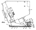
- Figure 1 is a side elevation of a control device formed by a scale upon which is mounted the payer.
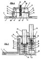
- Figure 2 is a top plan view of the scale of the device shown in figure 1.
- Figure 3 is a similar plan view to figure 2, cross-sectioned along the III-III line of figure 1.
- Figure 4 is a front elevation of the scale, in accordance with direction A of figure 2.
- Figure 5 is a partial vertical cross-section of the scale, taken from the V-V line of figure 2.
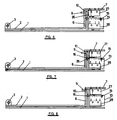
- Figures 6 to 8 are side views of the device of the invention, showing the scale in three extreme positions corresponding to three payer coin contents.
- the control device shown in figure 1 is formed by a scale formed by a fixed lower platform (1) and a tilting upper platform (2), which are connected to each other by the axis of articulation (3), which allows platform (2) to tilt with regard to platform (1).
- the payer (4) is mounted on the tilting platform (2), to which it is secured or attached via the anchorage base (5).
- a lug (9) which then juts out through a window (10) made in the portion (6) of the tilting platform, in a position adjoining portion (7) of the said platform.
- the partition (8) can be obtained from the fixed platform (1) by means of the cut (11) made in the said platform, as may be seen in figures 2 and 5.
- a helical spring (21) mounted between this head or wing and a support (20) attached to the fixed platform (1).
- a second screw (22) which also has, below the said lever, a head or wing (23).
- a second helical spring (25) mounted between this head or wing and a lower support (24) attached to the fixed platform (1).
- the tilting platform (2) is supported by the helical spring (21) through the screw (18).
- the weight borne by this tilting platform (2) reaches a given value, capable of overcoming the tension of spring (21)
- the platform tilts downwards, until the end of pivot (26) is resting on the middle section of the C-shaped lever (13).
- the tilting platform (2) is now supported by the helical spring (25), which will give way when the weight borne by the platform (2) reaches a second value.
- Figure 6 shows the scale in the position in which the tilting platform (2) would be when it holds a weight lower than the weight of the minimum number of coins that the payer must contain to ensure the payment of any prize obtained from the machine.
- spring (21) has not given way yet and switch (27) is separated from lever (13) and, therefore, is not enabled.
- the lug (9) of partition (8), figures 5 to 8, limits the highest position of the tilting platform (2). In the same way, lug (16) and window (17) limit the highest position of lever (13).
- the tilting platform (2) would be in the position shown in figure 6, in which switch (17) is open, keeping the machine switched off.
- the tension of springs (21) and (25) can be adjusted by turning screws (18) and (22), respectively, in order to adjust and adapt the device to different minimum and maximum weight values.
Landscapes
- Physics & Mathematics (AREA)
- General Physics & Mathematics (AREA)
- Control Of Vending Devices And Auxiliary Devices For Vending Devices (AREA)
- Control Of Conveyors (AREA)
Applications Claiming Priority (2)
| Application Number | Priority Date | Filing Date | Title |
|---|---|---|---|
| ES9600445 | 1996-02-26 | ||
| ES9600445A ES2113817B1 (es) | 1996-02-26 | 1996-02-26 | Dispositivo de control para pagadores de maquinas recreativas. |
Publications (1)
| Publication Number | Publication Date |
|---|---|
| EP0791903A1 true EP0791903A1 (fr) | 1997-08-27 |
Family
ID=8293943
Family Applications (1)
| Application Number | Title | Priority Date | Filing Date |
|---|---|---|---|
| EP97500039A Withdrawn EP0791903A1 (fr) | 1996-02-26 | 1997-02-19 | Machine de jeu avec dispositif de contrÔle de distribution |
Country Status (2)
| Country | Link |
|---|---|
| EP (1) | EP0791903A1 (fr) |
| ES (1) | ES2113817B1 (fr) |
Families Citing this family (1)
| Publication number | Priority date | Publication date | Assignee | Title |
|---|---|---|---|---|
| ES2160016B2 (es) * | 1998-08-19 | 2002-07-16 | Jofemar Sa | Devolvedor-contador de monedas. |
Citations (4)
| Publication number | Priority date | Publication date | Assignee | Title |
|---|---|---|---|---|
| US4036242A (en) * | 1973-08-01 | 1977-07-19 | Spiral Step Tool Company | Hopper payout for various coin denominations |
| AU547969B2 (en) * | 1981-08-17 | 1985-11-14 | Cope Allman (Marrickville) Pty. Ltd. | Accounting apparatus for gaming mach-nes |
| GB2221315A (en) * | 1987-07-09 | 1990-01-31 | Ainsworth Nominees Pty Ltd | Coin freed machines |
| US5326312A (en) * | 1991-09-13 | 1994-07-05 | Boardwalk Regency Corp. | Coin/token dispensing unit |
-
1996
- 1996-02-26 ES ES9600445A patent/ES2113817B1/es not_active Expired - Fee Related
-
1997
- 1997-02-19 EP EP97500039A patent/EP0791903A1/fr not_active Withdrawn
Patent Citations (4)
| Publication number | Priority date | Publication date | Assignee | Title |
|---|---|---|---|---|
| US4036242A (en) * | 1973-08-01 | 1977-07-19 | Spiral Step Tool Company | Hopper payout for various coin denominations |
| AU547969B2 (en) * | 1981-08-17 | 1985-11-14 | Cope Allman (Marrickville) Pty. Ltd. | Accounting apparatus for gaming mach-nes |
| GB2221315A (en) * | 1987-07-09 | 1990-01-31 | Ainsworth Nominees Pty Ltd | Coin freed machines |
| US5326312A (en) * | 1991-09-13 | 1994-07-05 | Boardwalk Regency Corp. | Coin/token dispensing unit |
Also Published As
| Publication number | Publication date |
|---|---|
| ES2113817B1 (es) | 1999-01-01 |
| ES2113817A1 (es) | 1998-05-01 |
Similar Documents
| Publication | Publication Date | Title |
|---|---|---|
| EP0076640B1 (fr) | Dispositif de manipulation de pièces | |
| EP0653084B1 (fr) | Appareil de manipulation de monnaies | |
| JP2024144695A (ja) | 景品取得ゲーム装置 | |
| US4872592A (en) | Article storage and dispensing device with sold out indicating mechanism | |
| KR930008626B1 (ko) | 이동식 캐비닛의 정지장치 | |
| US5501466A (en) | Coin projecting game apparatus | |
| EP0639395B1 (fr) | Tilt-interrupteur combiné à un indicateur d'inclinaison d'un plan de jeu | |
| PT83090B (pt) | Dispositivo de enchimento | |
| US5016745A (en) | Detection device for detecting that a coin receptacle is full | |
| JP2885371B1 (ja) | 弾球遊技機 | |
| US5988428A (en) | Vending machine for cans with dispensing rod | |
| EP0167181A2 (fr) | Dispositif pour le traitement de pièces de monnaie | |
| US20030096570A1 (en) | Coin handling device with folding escalator | |
| JP2980851B2 (ja) | 米びつ | |
| US20040224624A1 (en) | Token dispensing apparatus | |
| NO135702B (fr) | ||
| JP2859606B1 (ja) | 弾球遊技機 | |
| JP2579004Y2 (ja) | 硬貨処理機のホッパ | |
| ES2113817A1 (es) | Dispositivo de control para pagadores de maquinas recreativas. | |
| JP2755908B2 (ja) | パチンコ機 | |
| NO148238B (no) | Myntproever for utsortering av mynter som underskrider en minimal vekt. | |
| JP3088259B2 (ja) | 自動販売機のコイン払出装置 | |
| JPH0498385A (ja) | カード精算機 | |
| KR101851333B1 (ko) | 동전 배출구 | |
| US8002138B2 (en) | Item receiving systems and methods |
Legal Events
| Date | Code | Title | Description |
|---|---|---|---|
| PUAI | Public reference made under article 153(3) epc to a published international application that has entered the european phase |
Free format text: ORIGINAL CODE: 0009012 |
|
| AK | Designated contracting states |
Kind code of ref document: A1 Designated state(s): AT BE CH DE DK FI FR GB GR IE IT LI LU MC NL PT SE |
|
| 17P | Request for examination filed |
Effective date: 19971006 |
|
| 17Q | First examination report despatched |
Effective date: 19991125 |
|
| STAA | Information on the status of an ep patent application or granted ep patent |
Free format text: STATUS: THE APPLICATION HAS BEEN WITHDRAWN |
|
| 18W | Application withdrawn |
Withdrawal date: 20001116 |
|
| R18W | Application withdrawn (corrected) |
Effective date: 20001116 |