EP0791945A2 - Relais électromagnétique avec ressort de contact et de rappel combiné - Google Patents
Relais électromagnétique avec ressort de contact et de rappel combiné Download PDFInfo
- Publication number
- EP0791945A2 EP0791945A2 EP97102089A EP97102089A EP0791945A2 EP 0791945 A2 EP0791945 A2 EP 0791945A2 EP 97102089 A EP97102089 A EP 97102089A EP 97102089 A EP97102089 A EP 97102089A EP 0791945 A2 EP0791945 A2 EP 0791945A2
- Authority
- EP
- European Patent Office
- Prior art keywords
- spring
- contact
- relay according
- return
- armature
- Prior art date
- Legal status (The legal status is an assumption and is not a legal conclusion. Google has not performed a legal analysis and makes no representation as to the accuracy of the status listed.)
- Granted
Links
Images


Classifications
-
- H—ELECTRICITY
- H01—ELECTRIC ELEMENTS
- H01H—ELECTRIC SWITCHES; RELAYS; SELECTORS; EMERGENCY PROTECTIVE DEVICES
- H01H50/00—Details of electromagnetic relays
- H01H50/54—Contact arrangements
-
- H—ELECTRICITY
- H01—ELECTRIC ELEMENTS
- H01H—ELECTRIC SWITCHES; RELAYS; SELECTORS; EMERGENCY PROTECTIVE DEVICES
- H01H50/00—Details of electromagnetic relays
- H01H50/16—Magnetic circuit arrangements
- H01H50/18—Movable parts of magnetic circuits, e.g. armature
- H01H50/24—Parts rotatable or rockable outside coil
- H01H50/26—Parts movable about a knife edge
-
- H—ELECTRICITY
- H01—ELECTRIC ELEMENTS
- H01H—ELECTRIC SWITCHES; RELAYS; SELECTORS; EMERGENCY PROTECTIVE DEVICES
- H01H51/00—Electromagnetic relays
- H01H51/02—Non-polarised relays
- H01H51/04—Non-polarised relays with single armature; with single set of ganged armatures
- H01H51/06—Armature is movable between two limit positions of rest and is moved in one direction due to energisation of an electromagnet and after the electromagnet is de-energised is returned by energy stored during the movement in the first direction, e.g. by using a spring, by using a permanent magnet, by gravity
Definitions
- EP 0 375 398 A2 shows an unpoled relay with a flat magnet system and a normally open contact arrangement arranged below the magnet system.
- the contact spring is actuated there via a lever-like actuating member, which is itself pivotably mounted in the housing and has contact points with both the armature and the contact spring, each of which experiences relative movements with corresponding friction due to the separate mounting of the actuating member.
- the armature is reset there directly by the contact spring.
- the aim of the present invention is to improve the relay mentioned at the outset in such a way that a compact relay structure and a low-friction actuation of the contact spring can be achieved with as few and easily manufactured parts as possible.
- a switching spring with a reset function is to be realized, which enables the actuator to be guided precisely and with little friction, as a result of which a low response performance is also achieved.
- this switching spring it should also be possible with this switching spring to save a separate armature spring.
- this object is achieved in a relay of the type mentioned at the outset in that the return spring lies at least approximately in one plane with the contact spring and in that the actuating member which is movable perpendicular to the longitudinal extension of the switching spring is moved by the return spring at least two articulation points are guided along a line parallel to the pivot axis of the switching spring.
- a switching spring is used which essentially forms both the contact spring and the return spring in one common plane and in one piece and can be produced by a simple cutting process. It is of course not excluded that individual spring tabs, whether for resetting or for contact actuation, for example for adjustment, are easily bent out of the common spring plane.
- the return spring also forms at least two flush actuation points through which the actuator is gripped and guided with low friction, the spaced-apart articulation points simultaneously securing against lateral tilting and against friction on other structural parts.
- the return spring preferably has two separate return legs, which can either run on both sides of the actual contact spring on the outside or with a frame-shaped design of the contact spring inside its side legs.
- the actuator will be designed accordingly in any case.
- a symmetrical design of the switching spring is available, also with regard to a symmetrical distribution of forces with as little friction as possible.
- the two are Reset leg preferably formed by a fork-shaped design of the return spring, these two reset legs each extending next to the side legs of the contact spring within their frame shape.
- the coupling to the actuator is preferably carried out by guide lugs which are angled opposite each other and transversely to their longitudinal extension on the two return legs and engage in mutually aligned guide grooves of the actuator.
- the actuating member is adapted with its outer contour to the fork shape of the return spring and is guided between its return legs.
- the contact spring is expediently switched via at least one actuating tab which branches off from it and lies outside the current path, in each case by an associated switching cam of the actuating member, the switching cam being offset in the actuating direction in each case with respect to the articulation points of the return spring.
- This last-mentioned offset results in a different preload for the contact actuation and for the resetting of the armature even with a completely flat switching spring.
- the actuating tab located outside the current path has the advantage that it is heated less strongly at high switching powers than the actual current-carrying areas of the contact spring. This also avoids the risk of thermal deformation of the actuator.
- two actuating tabs from the contact section of the contact spring in the direction of the interior of its frame shape are also expedient branched and in such a way that their ends each face one end of a return leg.
- the magnet system has an essentially flat armature, which extends approximately parallel to the switching spring, is supported at one end by a bearing end section on a core section and with the other, movable end via the actuating member by the return spring is biased away from the magnet system, the armature with its central portion resting on a lever line parallel to the bearing axis of a base body so that its bearing end portion is pressed into the bearing due to the leverage.
- the switching spring can additionally press the armature into its mounting via the actuating member, so that it rests on the core even when the magnet system is not excited, so that an additional armature spring is not required.
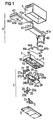
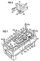
- the switching spring 21 forms, in one piece with the contact spring 22, a fork-shaped return spring 23, which is essentially separated from the fastening end 21a of the switching spring starting from the contact spring 22 and, with two return legs 23a, essentially parallel within the frame shape of the contact spring 22, parallel to its side legs 22a extends (see also Figure 3).
- the return spring 23 forms with its return legs 23a a U-shape, which is adapted to the outer contour of the actuator 3 to be described.
- the switching spring 21 is fastened at its fastening end 21a to a spring support 24, which in turn is anchored via fastening tabs 24a in insertion shafts 14 on opposite side walls 15 of the base body 1.
- the fastening tabs 24a have hook-shaped contours for better anchoring; there is also a terminal lug on the spring support 24 24b formed, which is guided through a corresponding opening in the base plate 5 to the outside.
- the contact arrangement further comprises an NC contact carrier 25 with an NC contact 26 and a NO contact carrier 27 with a normally open contact 28.
- Both contact carriers are anchored in corresponding plug shafts 16 of the base body 1 via fastening sections 25a and 27a.
- they each have terminal lugs 25b and 27b, which are guided through the base plate 5 to the outside.
- the contact carriers 25 and 27 are designed and arranged in the contact space 13a so that the movable contact 29 optionally cooperates with the normally closed contact 26 and the normally open contact 28.
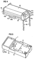
- the magnet system 4 arranged above the base body has a coil body 41 with a winding 42, the axis of which lies parallel to the bottom side of the relay.
- a core yoke 43 integrally forms a core leg 43a, which extends axially through the entire coil, and a yoke leg 43b, which extends parallel to the core leg below the coil, close to the winding, up to approximately half the coil length.
- An armature 44 extends with its main part flatly in the extension of the yoke leg 43b, a pole end section 44a which is set back in cross section overlapping a pole section 43c of the yoke leg which is also reduced in cross section.
- a bearing end portion 44b of the armature is angled toward the free core end 43d and is mounted in a pocket 45 of a coil former flange 41a such that it rolls on the free core end 43d.
- the coil former flange 41a surrounds this free core end 43d on three sides and secures it the bearing end portion 44b of the armature with retaining ribs 41b also against wandering away in the axial direction of the coil. Otherwise, this armature end portion 44b of the armature is pressed into the bearing on the core end 43d by the restoring force of the restoring spring 23. This restoring force acts on the movable armature end 44c and pulls it downward away from the coil.
- the armature is pivoted as a lever when the magnet system is not excited about a rolling edge 17 on the upper side of the partition 11 - counterclockwise in the illustration of FIG. 2 - in such a way that the bearing end section 44b of the armature is prestressed into the bearing. In this way, a separate bearing spring is not necessary.
- the arrangement of the yoke leg 43b directly on the winding 42 pulls the armature 44 toward the coil when the magnet system is excited, so that the switching spring 21 is also pulled in this direction via the actuating member 3.
- the actuator 3 which transmits the switching movement of the armature, has a hook part 31 which passes through the opening 12 of the partition 11 substantially perpendicular to the base plane and is hooked to an opening 44d of the armature 44 with its hook-shaped end.
- a recess 43e is also provided in the pole section 43c of the pole leg 43b, which enables the armature to be placed completely against the yoke leg in this region.
- the actuator has a flat foot portion 32 which lies substantially in the plane of the switching spring 21 and in this example has an M-shaped shape.
- the middle leg of the M is connected to the hook part 31.
- a guide groove 33 is formed in each of the two outer legs of the foot part 32, in each of which a guide lug 23b of the adjacent reset leg 23a engages.
- An actuating cam 34 is formed laterally on each of the free ends of these outer legs and lies below the adjacent actuating tab 22d of the contact spring and, when the actuating member 3 moves upward, brings the contact spring into the closed position.
- the return position of the armature with respect to the closed position of the normally closed contact can be set, even if the return spring and the contact spring are originally in one plane. Otherwise, a corresponding position can also be adjusted by slightly bending the reset legs 23a on the one hand and the actuating tabs 22c on the other.
- the relay is installed in such a way that the magnet system according to FIG. 4 is preassembled on the one hand and on the other hand the contact arrangement 3 is anchored in the base body from the underside.
- the magnet system according to FIG. 4 is put together with the base body according to FIG. 5, coil connecting pins 46 being inserted into corresponding openings in the base body.
- the actuator 3 is inserted from the bottom through the frame-shaped switching spring and hooked into the armature.
- the actuating member 3 is first guided upwards in an inclined position, as shown in dashed lines in FIG. 2 with the reference symbol 3 ', inserted with the hook part 31 into the opening 12 and then pivoted into the final position.
- This type of assembly of the actuator without snap connections also avoids any plastic abrasion that could endanger the contacts.
- the housing is then formed, which can also be sealed in a known manner.
- This has a U-shaped shape with two hook parts 131 as outer legs and a foot part 132 connecting the two hook parts, which extends below the switching spring transversely to the latter and has both a central cam section 134 for actuating the contact spring 122 and two laterally arranged guide grooves 133 for Includes the mentioned guide tabs 123b.
- the two hook parts 131 extend up to the anchor, the anchor of course being designed accordingly on both sides to allow hooking of the hook parts 131, and the base body in its partition instead of the previously described central opening 12 now two on the outside must have horizontal openings.
- the spring support 24 is designed as in the previous embodiment.
- FIG. 9 shows a further modification compared to FIG. 8.
- the switching spring 221 has a central contact spring 222 with a contact section 222b and a return spring 223 formed by outside return legs 223a, the return legs each having a guide lug 223b at their ends.
- the actuator 203 is similar to the actuator 103 U-shaped. It has two hook parts 231 and a transverse foot part 232, in which guide grooves 233 are formed for receiving the guide lugs 223b.
- the contact spring 222 is now not actuated directly on the center leg 222a, but rather via actuating tabs 222c formed on the side, which are approximately aligned with the restoring legs 223a and each rest on an actuating cam 234 of the actuating member 203.
- the function for adapting the armature and the base body to the modified actuator is the same as for FIG. 8. Otherwise, the function results from the description of the first exemplary embodiment.
Landscapes
- Physics & Mathematics (AREA)
- Electromagnetism (AREA)
- Electromagnets (AREA)
- Mechanical Operated Clutches (AREA)
- Braking Arrangements (AREA)
- Switch Cases, Indication, And Locking (AREA)
- Cookers (AREA)
- Push-Button Switches (AREA)
- Relay Circuits (AREA)
Applications Claiming Priority (2)
| Application Number | Priority Date | Filing Date | Title |
|---|---|---|---|
| DE19606883 | 1996-02-23 | ||
| DE19606883A DE19606883C1 (de) | 1996-02-23 | 1996-02-23 | Elektromagnetisches Relais mit kombinierter Kontakt- und Rückstellfeder |
Publications (3)
| Publication Number | Publication Date |
|---|---|
| EP0791945A2 true EP0791945A2 (fr) | 1997-08-27 |
| EP0791945A3 EP0791945A3 (fr) | 1998-11-18 |
| EP0791945B1 EP0791945B1 (fr) | 2002-01-09 |
Family
ID=7786274
Family Applications (1)
| Application Number | Title | Priority Date | Filing Date |
|---|---|---|---|
| EP97102089A Expired - Lifetime EP0791945B1 (fr) | 1996-02-23 | 1997-02-10 | Relais électromagnétique avec ressort de contact et de rappel combiné |
Country Status (6)
| Country | Link |
|---|---|
| US (1) | US5801608A (fr) |
| EP (1) | EP0791945B1 (fr) |
| JP (1) | JP3902688B2 (fr) |
| AT (1) | ATE211851T1 (fr) |
| DE (2) | DE19606883C1 (fr) |
| ES (1) | ES2167627T3 (fr) |
Families Citing this family (11)
| Publication number | Priority date | Publication date | Assignee | Title |
|---|---|---|---|---|
| DE19627845C1 (de) * | 1996-07-10 | 1997-09-18 | Siemens Ag | Verfahren zur Herstellung eines elektromagnetischen Relais |
| DE19816878C2 (de) * | 1998-04-17 | 2003-11-13 | Hengstler Gmbh | Zwillingsrelais |
| JP2003151419A (ja) * | 2001-08-31 | 2003-05-23 | Omron Corp | 電磁継電器 |
| DE102006007603B4 (de) | 2006-02-18 | 2008-04-30 | Tyco Electronics Austria Gmbh | Relais mit reduziertem Kriechstrom |
| CN101984504B (zh) * | 2010-09-06 | 2012-11-14 | 厦门宏发电力电器有限公司 | 一种具有双柔性推动连接的磁保持继电器 |
| CN202650990U (zh) * | 2012-07-02 | 2013-01-02 | 宁波福特继电器有限公司 | 一种小型大功率磁保持继电器 |
| GB201402560D0 (en) * | 2014-02-13 | 2014-04-02 | Johnson Electric Sa | Improvements in or relating to electrical contactors |
| CN104538250B (zh) * | 2015-02-03 | 2016-08-24 | 佛山市川东磁电股份有限公司 | 一种磁力开关 |
| CH713442B1 (de) * | 2017-02-08 | 2021-03-31 | Elesta Gmbh Ostfildern De Zweigniederlassung Bad Ragaz | Relais. |
| JP7638633B2 (ja) | 2020-06-30 | 2025-03-04 | Fclコンポーネント株式会社 | 電磁継電器 |
| CN115831671B (zh) * | 2022-11-04 | 2025-10-10 | 昆山国力电子科技股份有限公司 | 小尺寸高压直流接触器 |
Family Cites Families (11)
| Publication number | Priority date | Publication date | Assignee | Title |
|---|---|---|---|---|
| DE2627168C3 (de) * | 1976-06-16 | 1983-12-15 | Siemens AG, 1000 Berlin und 8000 München | Elektromagnetisches Relais mit zur Ankerrückstellung dienender Kontaktfeder |
| DE3238223C2 (de) * | 1982-10-15 | 1986-07-17 | Standard Elektrik Lorenz Ag, 7000 Stuttgart | Elektrisches Miniatur-Kompaktrelais |
| US4688010A (en) * | 1984-12-22 | 1987-08-18 | Matsushita Electric Works, Ltd. | Electromagnetic relay |
| US4600909A (en) * | 1985-05-20 | 1986-07-15 | Amf Incorporated | Bifurcated contact arm in a miniature relay |
| US4720694A (en) * | 1985-05-22 | 1988-01-19 | Siemens Aktiengesellschaft | Electromagnetic relay |
| DE3520773C1 (de) * | 1985-05-29 | 1989-07-20 | SDS-Relais AG, 8024 Deisenhofen | Elektromagnetisches Relais |
| DE3644172A1 (de) * | 1986-12-23 | 1988-07-07 | Bbc Brown Boveri & Cie | Elektromagnetischer schalterantrieb fuer ein elektrisches schaltgeraet |
| DE3889947T2 (de) * | 1987-03-06 | 1994-11-03 | Takamisawa Electric Co | Elektromagnetisches Relais mit Vorrichtungen zur Herabsetzung des Geräusches. |
| JPH0733344Y2 (ja) * | 1988-12-23 | 1995-07-31 | 松下電工株式会社 | 電磁継電器 |
| DE3908442A1 (de) * | 1989-03-15 | 1990-10-11 | Eberle Gmbh | Elektromagnetisches schaltgeraet |
| DE9303437U1 (de) * | 1993-03-09 | 1993-08-26 | Kosowski, Dimiter, Dr.-Ing., 58509 Lüdenscheid | Elektromagnetisches Kleinrelais |
-
1996
- 1996-02-23 DE DE19606883A patent/DE19606883C1/de not_active Expired - Fee Related
-
1997
- 1997-02-10 DE DE59705943T patent/DE59705943D1/de not_active Expired - Lifetime
- 1997-02-10 EP EP97102089A patent/EP0791945B1/fr not_active Expired - Lifetime
- 1997-02-10 AT AT97102089T patent/ATE211851T1/de not_active IP Right Cessation
- 1997-02-10 ES ES97102089T patent/ES2167627T3/es not_active Expired - Lifetime
- 1997-02-24 US US08/804,608 patent/US5801608A/en not_active Expired - Lifetime
- 1997-02-24 JP JP03872197A patent/JP3902688B2/ja not_active Expired - Lifetime
Also Published As
| Publication number | Publication date |
|---|---|
| EP0791945B1 (fr) | 2002-01-09 |
| JPH09320438A (ja) | 1997-12-12 |
| EP0791945A3 (fr) | 1998-11-18 |
| DE59705943D1 (de) | 2002-02-14 |
| DE19606883C1 (de) | 1997-04-30 |
| ATE211851T1 (de) | 2002-01-15 |
| JP3902688B2 (ja) | 2007-04-11 |
| US5801608A (en) | 1998-09-01 |
| ES2167627T3 (es) | 2002-05-16 |
Similar Documents
| Publication | Publication Date | Title |
|---|---|---|
| EP0791944B1 (fr) | Relais électromagnétique | |
| DE4135305C2 (fr) | ||
| DE3808558C2 (fr) | ||
| EP0895265B1 (fr) | Relais électromagnétique | |
| EP0363976B1 (fr) | Relais électromagnétique | |
| EP0791945B1 (fr) | Relais électromagnétique avec ressort de contact et de rappel combiné | |
| DE68921449T2 (de) | Elektromagnetisches Relais. | |
| EP0033841B1 (fr) | Relais | |
| DE602005000652T2 (de) | Elektromagnetisches Relais | |
| EP0203515B1 (fr) | Relais électromagnétique | |
| DE3122758A1 (de) | Betaetigungsschalter | |
| WO1998050933A1 (fr) | Relais a bancs de contact | |
| EP0872865B1 (fr) | Relais éléctromagnétique | |
| DE3132239C2 (de) | Elektromagnetisches Relais | |
| EP0876674A1 (fr) | Relais electromagnetique de structure etroite et procede permettant de le produire | |
| EP0707331B1 (fr) | Relais | |
| EP0476182B1 (fr) | Contacteur électromagnétique avec un coulisseau de commande | |
| EP0099019A1 (fr) | Relais avec ressort de contact de pontage | |
| EP0846330B1 (fr) | Relais electromagnetique et son utilisation sur une carte de circuits imprimes | |
| EP0980578A1 (fr) | Relais electromagnetique | |
| EP0763247B1 (fr) | Interrupteur a action brusque, a deplacement rectiligne du contact et systeme d'interrupteur associe | |
| EP0091687A1 (fr) | Relais électromagnétique | |
| DE3600856A1 (de) | Sicherheits-schaltrelais | |
| DE3329239A1 (de) | Elektromagnetisches relais | |
| DE4232228C2 (de) | Relais |
Legal Events
| Date | Code | Title | Description |
|---|---|---|---|
| PUAI | Public reference made under article 153(3) epc to a published international application that has entered the european phase |
Free format text: ORIGINAL CODE: 0009012 |
|
| AK | Designated contracting states |
Kind code of ref document: A2 Designated state(s): AT CH DE ES FR GB IT LI |
|
| PUAL | Search report despatched |
Free format text: ORIGINAL CODE: 0009013 |
|
| AK | Designated contracting states |
Kind code of ref document: A3 Designated state(s): AT CH DE ES FR GB IT LI |
|
| 17P | Request for examination filed |
Effective date: 19981204 |
|
| RAP1 | Party data changed (applicant data changed or rights of an application transferred) |
Owner name: TYCO ELECTRONICS GMBH |
|
| GRAG | Despatch of communication of intention to grant |
Free format text: ORIGINAL CODE: EPIDOS AGRA |
|
| 17Q | First examination report despatched |
Effective date: 20010307 |
|
| RAP1 | Party data changed (applicant data changed or rights of an application transferred) |
Owner name: TYCO ELECTRONICS AUSTRIA GMBH |
|
| GRAG | Despatch of communication of intention to grant |
Free format text: ORIGINAL CODE: EPIDOS AGRA |
|
| GRAH | Despatch of communication of intention to grant a patent |
Free format text: ORIGINAL CODE: EPIDOS IGRA |
|
| GRAH | Despatch of communication of intention to grant a patent |
Free format text: ORIGINAL CODE: EPIDOS IGRA |
|
| GRAA | (expected) grant |
Free format text: ORIGINAL CODE: 0009210 |
|
| REG | Reference to a national code |
Ref country code: GB Ref legal event code: IF02 |
|
| AK | Designated contracting states |
Kind code of ref document: B1 Designated state(s): AT CH DE ES FR GB IT LI |
|
| REF | Corresponds to: |
Ref document number: 211851 Country of ref document: AT Date of ref document: 20020115 Kind code of ref document: T |
|
| REG | Reference to a national code |
Ref country code: CH Ref legal event code: EP |
|
| REF | Corresponds to: |
Ref document number: 59705943 Country of ref document: DE Date of ref document: 20020214 |
|
| PG25 | Lapsed in a contracting state [announced via postgrant information from national office to epo] |
Ref country code: LI Free format text: LAPSE BECAUSE OF NON-PAYMENT OF DUE FEES Effective date: 20020228 Ref country code: CH Free format text: LAPSE BECAUSE OF NON-PAYMENT OF DUE FEES Effective date: 20020228 |
|
| GBT | Gb: translation of ep patent filed (gb section 77(6)(a)/1977) |
Effective date: 20020404 |
|
| ET | Fr: translation filed | ||
| REG | Reference to a national code |
Ref country code: ES Ref legal event code: FG2A Ref document number: 2167627 Country of ref document: ES Kind code of ref document: T3 |
|
| REG | Reference to a national code |
Ref country code: CH Ref legal event code: PL |
|
| PLBE | No opposition filed within time limit |
Free format text: ORIGINAL CODE: 0009261 |
|
| STAA | Information on the status of an ep patent application or granted ep patent |
Free format text: STATUS: NO OPPOSITION FILED WITHIN TIME LIMIT |
|
| 26N | No opposition filed | ||
| PGFP | Annual fee paid to national office [announced via postgrant information from national office to epo] |
Ref country code: AT Payment date: 20030415 Year of fee payment: 7 |
|
| PG25 | Lapsed in a contracting state [announced via postgrant information from national office to epo] |
Ref country code: AT Free format text: LAPSE BECAUSE OF NON-PAYMENT OF DUE FEES Effective date: 20040210 |
|
| REG | Reference to a national code |
Ref country code: FR Ref legal event code: PLFP Year of fee payment: 20 |
|
| PGFP | Annual fee paid to national office [announced via postgrant information from national office to epo] |
Ref country code: DE Payment date: 20160226 Year of fee payment: 20 Ref country code: ES Payment date: 20160226 Year of fee payment: 20 Ref country code: IT Payment date: 20160223 Year of fee payment: 20 |
|
| PGFP | Annual fee paid to national office [announced via postgrant information from national office to epo] |
Ref country code: GB Payment date: 20160226 Year of fee payment: 20 Ref country code: FR Payment date: 20160217 Year of fee payment: 20 |
|
| REG | Reference to a national code |
Ref country code: DE Ref legal event code: R071 Ref document number: 59705943 Country of ref document: DE |
|
| REG | Reference to a national code |
Ref country code: GB Ref legal event code: PE20 Expiry date: 20170209 |
|
| PG25 | Lapsed in a contracting state [announced via postgrant information from national office to epo] |
Ref country code: GB Free format text: LAPSE BECAUSE OF EXPIRATION OF PROTECTION Effective date: 20170209 |
|
| REG | Reference to a national code |
Ref country code: ES Ref legal event code: FD2A Effective date: 20180508 |
|
| PG25 | Lapsed in a contracting state [announced via postgrant information from national office to epo] |
Ref country code: ES Free format text: LAPSE BECAUSE OF EXPIRATION OF PROTECTION Effective date: 20170211 |