EP0791950B1 - Lampe à décharge du type à arc court - Google Patents
Lampe à décharge du type à arc court Download PDFInfo
- Publication number
- EP0791950B1 EP0791950B1 EP97102911A EP97102911A EP0791950B1 EP 0791950 B1 EP0791950 B1 EP 0791950B1 EP 97102911 A EP97102911 A EP 97102911A EP 97102911 A EP97102911 A EP 97102911A EP 0791950 B1 EP0791950 B1 EP 0791950B1
- Authority
- EP
- European Patent Office
- Prior art keywords
- anode
- discharge lamp
- arc type
- short arc
- tip
- Prior art date
- Legal status (The legal status is an assumption and is not a legal conclusion. Google has not performed a legal analysis and makes no representation as to the accuracy of the status listed.)
- Expired - Lifetime
Links
Images


Classifications
-
- H—ELECTRICITY
- H01—ELECTRIC ELEMENTS
- H01J—ELECTRIC DISCHARGE TUBES OR DISCHARGE LAMPS
- H01J3/00—Details of electron-optical or ion-optical arrangements common to two or more basic types of discharge tubes or lamps
-
- G—PHYSICS
- G03—PHOTOGRAPHY; CINEMATOGRAPHY; ANALOGOUS TECHNIQUES USING WAVES OTHER THAN OPTICAL WAVES; ELECTROGRAPHY; HOLOGRAPHY
- G03F—PHOTOMECHANICAL PRODUCTION OF TEXTURED OR PATTERNED SURFACES, e.g. FOR PRINTING, FOR PROCESSING OF SEMICONDUCTOR DEVICES; MATERIALS THEREFOR; ORIGINALS THEREFOR; APPARATUS SPECIALLY ADAPTED THEREFOR
- G03F7/00—Photomechanical, e.g. photolithographic, production of textured or patterned surfaces, e.g. printing surfaces; Materials therefor, e.g. comprising photoresists; Apparatus specially adapted therefor
- G03F7/70—Microphotolithographic exposure; Apparatus therefor
- G03F7/70008—Production of exposure light, i.e. light sources
- G03F7/70016—Production of exposure light, i.e. light sources by discharge lamps
-
- H—ELECTRICITY
- H01—ELECTRIC ELEMENTS
- H01J—ELECTRIC DISCHARGE TUBES OR DISCHARGE LAMPS
- H01J61/00—Gas-discharge or vapour-discharge lamps
- H01J61/02—Details
- H01J61/04—Electrodes; Screens; Shields
- H01J61/06—Main electrodes
- H01J61/073—Main electrodes for high-pressure discharge lamps
Definitions
- the invention relates to a discharge lamp of the short arc type.
- the lamp current is multiplied in this way, the anode temperature increases even more as a result of collision of the multiplied electron current. Furthermore, the effect is to suppress the vaporization of the anode material by the above described mercury because the mercury pressure within the arc tube is low. Consequently, the disadvantages were premature vaporization of the anode, blackening of the inside wall of the arc tube and shortening of the service life.
- Japanese patent disclosure document HEI 2-256150 discloses a process for suppressing this vaporization of the anode part.
- the anode surface outside its tip includes porous layers consisting of a mixture of tantalum carbide and tungsten in order to reduce the anode temperature during luminous operation of the lamp.
- the disclosure discusses increasing the effective surface area of the anode, multiplying the radiation from the above described surface, and, thus, reducing the anode temperature, and the like.
- tantalum carbide due to its higher radiation capacity than tungsten is therefore also used to increase the radiation effect.
- tantalum carbide has the property of decomposing by reduction in an area with a high temperature in the vicinity of the electrode tips. This means that for this reason the area in which the mixed layers could be formed was limited, although actually the mixed layers of the tantalum carbide and tungsten should be formed into near the above described tip to cool the temperature of the anode tip which has the highest temperature.
- US-A-3,248,591 discloses a discharge lamp of the short arc type wherein the anode consists of a solid tungsten piece, the body of which is provided with annular grooves. The grooved areas, outside the tip of the anode, are coated with sintered layers of tungsten powder or tantalum carbide.
- the discharge lamp of the short arc type by providing sintered layers of fine-particle tungsten formed on the outside surface of the anode near its tip according to the condition 0.1 D ⁇ x ⁇ 0,45D, fine concave-convex areas are formed on the anode surface, the effective surface area of the anode is increased, the temperature increase of the anode tip in luminous operation is suppressed, premature vaporization of the anode part is prevented, and blackening of the inside wall of the arc tube is suppressed.
- the distance between the tip of the anode and the boundary of the area in which the sintered layers of the fine-particle tungsten are formed is labelled x, and the diameter of the body of the anode is labelled D.
- FIG. 1 is a schematic of discharge lamp of the short arc type 1 which is used for the invention.
- a transparent arc tube 2 there are a cathode 3 and anode 4 opposite one another.
- Reference number 5 is a base.
- Sintered layers 6 of fine-particle tungsten are formed on the outside surface of anode 4 outside of its tip.
- Anode 4 consists of a material with a high melting point, such as tungsten, molybdenum, or the like.
- At least one metal such as Hg, Cd, Zn or the like, at least one rare gas such as Xe, Ar, Kr, Ne or the like, and at least one metal halide or the like are suitably encapsulated in arc tube 2 as emission substances according to the required radiant light from the above described discharge lamp of the short arc type.
- a high pressure mercury vapor lamp of the short arc type which is used as a light source for lithography in a process of producing semiconductor components.
- the outside layer of the above described high pressure mercury vapor lamp of the short arc type is identical to Figure 1.
- arc tube 2 consisting of quartz glass, Hg and rare gas are encapsulated as the emission substances.
- Anode 4 consists of tungsten.
- Figure 2 shows anode 4 in an enlarged view. In a predetermined surface area of anode 4 sintered layers 6 of fine-particle tungsten are formed.
- Figure 3 schematically shows another embodiment of anode 4 in the discharge lamp according to the invention in which tip part 8 of the anode is round.
- the diameter of body 7 of anode 4 is labelled D (mm) and the distance between tip part 8 of above described anode 4 and the boundary to the area in which sintered layers 6 of fine-particle tungsten are present is labeled x (mm).
- the expression "fine-particle tungsten” is defined as particulate tungsten with a grain size of roughly 0.1 to 100 microns.
- fine tungsten particles with an average grain see of 3 microns are mixed in a solvent of nitrocellulose and butyl acetate.
- a solution in which these fine tungsten particles are dispersed is applied using a brush or the like proceeding from the predetermined surface area of anode 4, i.e., preceding from an area spaced apart from tip part 8 of the anode with a distance x (0.1D ⁇ x ⁇ 0.45D).
- sintering treatment was done in which the anode was kept for two hours in a vacuum atmosphere of 2 x 10 -4 Pa at a temperature of 2200°C.
- the thickness of sintered layer 6 of the fine-particle tungsten is not particularly limited, but is, for example, roughly 1 to 10 microns.
- Figure 4 is a schematic which reproduces the result of measurements in which the anode temperature in luminous operation of the discharge lamp of the short arc type according to the invention was compared to the anode temperature in luminous operation of a conventional discharge lamp of the short arc type. In this case, the anode was not subjected to treatment for purposes of radiation in the conventional discharge lamp of the short arc type.
- Temperature measurements were taken as follows. Specifically, at a point which is 20 cm away from the anode tip of the discharge lamp to be measured in the direction perpendicular to the longitudinal direction of this discharge lamp, there is an infrared radiation thermometer with an angle of the measurement field of view which is 0.1 mm in diameter. It was provided that the anode tip with the temperature to be measured extends into this angle of the measurement field of view. By measuring the intensity of the infrared radiation (1.35 microns) emitted from the lamp, the result is converted into a temperature.
- Each of the discharge lamps of the short arc type in which the temperatures of the anode tips were measured is a high pressure mercury vapor lamp of the short arc type with an output of 1.75 kW.
- Diameter D of body 7 of the anode is 18 mm.
- Figure 4 shows curve (a) which is the result of measurement of the anode temperature of the conventional discharge lamp and curves (b) and (c) which are the result of measuring the anode temperature of the discharge lamp according to the invention.
- the area in which sintered layers 6 of fine-particle tungsten are formed is at (b) starting from a position with a distance of 0.56D from anode tip 8, while it is at (c) starting at a position with a distance of 0.33D from anode tip 8.
- the temperature of anode tip 8 is reduced; this is most effective for suppressing the vaporization of anode 4.
- the latter has a temperature which is roughly 120 K lower than in the conventional discharge lamp of the short arc type, in which anode 4 has not been subjected to treatment for purposes of radiation. This means that the amount of tungsten which is vaporized by anode 4 is reduced, by which blackening of the wall of arc tube 2 is suppressed, and by which the degree to which irradiance is maintained is improved.
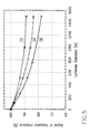
- Figure 5 is a schematic which reproduces the result of measurements in which the degree was measured to which the horizontal irradiance was maintained in the high pressure mercury vapor lamp of the short arc type used for the invention and in the conventional high pressure mercury vapor lamp of the short arc type, in which anode 4 has not been subjected to treatment for radiation.
- the lamps used for the measurements are the same as those which were used for the above described measurements of the anode temperature.
- curve (d) shows the measurement result for a conventional discharge lamp and curves (e) and (f) show the measurement result for the discharge lamp according to the invention.
- the area in which sintered layers 6 of fine-particle tungsten are formed has the condition of 0.56D for (e) and 0.33D for (f).
- the process of measuring the degree to which the horizontal irradiance is maintained is described. Specifically, the high pressure mercury vapor lamp of the discharge type is kept vertical and subjected to luminous operation. At a point which is horizontally apart from the cathode tip with a distance of 50 cm there is a bandpass filter that permits the passage of ultraviolet rays with wavelengths around 365 nm. Directly behind the above described bandpass filter is a detector using a silicon photodiode and with it the irradiance was measured.
- a high pressure mercury vapor lamp of the short arc type was described specifically above.
- the invention can also be used for a xenon discharge lamp, a xenon-mercury discharge lamp, a discharge lamp in which cadmium, zinc, or the like are encapsulated in the arc tube, or for a metal halide lamp in which at least one metal halide is encapsulated, if the lamp is a discharge lamp of the short arc type.
- the material for the anode is not limited to tungsten.
- another material with a high melting point such as molybdenum, tantalum, or the like, the same effect of suppression of vaporization of the anode can be obtained by the sintered layers according to the invention being formed on the outside surface of the anode outside of the vicinity of the tip in accordance with the condition 0.1 D ⁇ x ⁇ 0.45 D.
- the discharge lamp of the short arc type according to the invention by sintering the sintered layers of fine-particle tungsten on the outside surface of the anode outside of its tip, on the anode surface fine, concave-convex areas are formed by which the effective surface area of the anode and the thermal radiation are multiplied.
- the anode temperature therefore drops, and continuation of blackening of the arc tube wall is suppressed.
- the above described sintered layers can be formed by using tungsten in which the melting point is high for the sintered layers for radiation of the anode into the vicinity of the anode tip where the temperature rises most during luminous operation.
Landscapes
- Physics & Mathematics (AREA)
- Engineering & Computer Science (AREA)
- Plasma & Fusion (AREA)
- General Physics & Mathematics (AREA)
- Discharge Lamp (AREA)
Claims (2)
- Lampe à décharge (1) du type à arc court, comprenant :caractérisée en ce que 0,1D ≤ x ≤ 0,45 D, où x est une distance, mesurée dans une direction longitudinale de la lampe à décharge (1), entre la pointe (8) de ladite anode (4) et une limite, dans le voisinage de la pointe, de l'aire dans laquelle sont formées lesdites couches frittées (6) de tungstène en fines particules, et où D est un diamètre d'un corps (7) de ladite anode (4).un tube à arc (2) ;des substances d'émission, encapsulées à l'intérieur dudit tube à arc,une anode (4) et une cathode (3) placées en vis à vis à l'intérieur dudit tube à arc, dans laquelle une surface extérieure de ladite anode (4) comprend des couches frittées (6) de tungtène en fines particules, placées à l'extérieur des abords d'une pointe (8) de ladite anode (4),
- Lampe à décharge selon la Revendication 1, dans laquelle Hg et au moins l'un des gaz rares Xe, Ar, Kr, ou Ne, sont encapsulés dans ledit tube à arc (2).
Applications Claiming Priority (3)
| Application Number | Priority Date | Filing Date | Title |
|---|---|---|---|
| JP8060357A JPH09231946A (ja) | 1996-02-23 | 1996-02-23 | ショートアーク型放電ランプ |
| JP6035796 | 1996-02-23 | ||
| JP60357/96 | 1996-02-23 |
Publications (3)
| Publication Number | Publication Date |
|---|---|
| EP0791950A2 EP0791950A2 (fr) | 1997-08-27 |
| EP0791950A3 EP0791950A3 (fr) | 1997-12-10 |
| EP0791950B1 true EP0791950B1 (fr) | 2001-03-28 |
Family
ID=13139834
Family Applications (1)
| Application Number | Title | Priority Date | Filing Date |
|---|---|---|---|
| EP97102911A Expired - Lifetime EP0791950B1 (fr) | 1996-02-23 | 1997-02-21 | Lampe à décharge du type à arc court |
Country Status (6)
| Country | Link |
|---|---|
| US (1) | US5929565A (fr) |
| EP (1) | EP0791950B1 (fr) |
| JP (1) | JPH09231946A (fr) |
| KR (1) | KR100428960B1 (fr) |
| DE (1) | DE69704385T2 (fr) |
| TW (1) | TW408852U (fr) |
Families Citing this family (24)
| Publication number | Priority date | Publication date | Assignee | Title |
|---|---|---|---|---|
| DE19652822A1 (de) | 1996-12-18 | 1998-06-25 | Patent Treuhand Ges Fuer Elektrische Gluehlampen Mbh | Sinterelektrode |
| US6215247B1 (en) * | 1997-10-03 | 2001-04-10 | Orc Manufacturing Co., Ltd. | Construction of electrode for high pressure discharge lamp and process for producing the same |
| DE29823366U1 (de) * | 1998-08-06 | 1999-07-08 | Patent-Treuhand-Gesellschaft für elektrische Glühlampen mbH, 81543 München | Elektrode für eine Hochdruckentladungslampe mit langer Lebensdauer |
| JP2000306546A (ja) * | 1999-04-21 | 2000-11-02 | Ushio Inc | ショートアーク放電ランプ |
| JP2005108435A (ja) * | 1999-06-30 | 2005-04-21 | Hamamatsu Photonics Kk | フラッシュランプ |
| AU745886B2 (en) * | 1999-12-20 | 2002-04-11 | Toshiba Lighting & Technology Corporation | A high-pressure metal halide A.C. discharge lamp and a lighting apparatus using the lamp |
| JP4512968B2 (ja) | 2000-08-03 | 2010-07-28 | ウシオ電機株式会社 | ショートアーク型高圧放電ランプ |
| JP3596453B2 (ja) * | 2000-09-28 | 2004-12-02 | ウシオ電機株式会社 | ショートアーク放電ランプ |
| JP3846282B2 (ja) * | 2001-11-21 | 2006-11-15 | ウシオ電機株式会社 | ショートアーク型高圧放電ランプ |
| JP4295527B2 (ja) * | 2003-02-27 | 2009-07-15 | 株式会社アライドマテリアル | 放電ランプ及びその電極構造 |
| JP4042605B2 (ja) * | 2003-03-31 | 2008-02-06 | ウシオ電機株式会社 | キセノンランプ |
| JP4714418B2 (ja) * | 2004-03-02 | 2011-06-29 | ウシオ電機株式会社 | 放電ランプ |
| US20060175973A1 (en) * | 2005-02-07 | 2006-08-10 | Lisitsyn Igor V | Xenon lamp |
| JP2009105059A (ja) * | 2009-01-05 | 2009-05-14 | Allied Material Corp | 放電ランプの電極構造 |
| DE102009021235B4 (de) * | 2009-05-14 | 2018-07-26 | Osram Gmbh | Entladungslampe mit beschichteter Elektrode |
| JP5299132B2 (ja) * | 2009-07-07 | 2013-09-25 | ウシオ電機株式会社 | デジタルプロジェクター用キセノンショートアークランプ |
| JP5584093B2 (ja) * | 2010-11-05 | 2014-09-03 | 株式会社ユメックス | ショートアーク放電灯用陰極およびその製造方法 |
| JP6487720B2 (ja) * | 2015-03-03 | 2019-03-20 | 株式会社ユメックス | ショートアーク放電ランプ用陽極およびその製法 |
| US20160358751A1 (en) * | 2015-06-03 | 2016-12-08 | Jong-Hyun Lee | Arc discharge apparatus and plasma processing system including the same |
| JP6647678B2 (ja) * | 2015-12-02 | 2020-02-14 | 岩崎電気株式会社 | ショートアーク型放電ランプ |
| AT15991U1 (de) | 2017-05-12 | 2018-10-15 | Plansee Se | Hochtemperaturkomponente |
| KR20220054888A (ko) * | 2020-04-30 | 2022-05-03 | 유멕스 인크. | 쇼트 아크 방전 램프용 전극 및 그 생성 방법 |
| JP7413939B2 (ja) * | 2020-06-29 | 2024-01-16 | ウシオ電機株式会社 | ショートアーク型放電ランプ |
| JP7121932B2 (ja) * | 2020-07-27 | 2022-08-19 | ウシオ電機株式会社 | ショートアーク型放電ランプ |
Family Cites Families (7)
| Publication number | Priority date | Publication date | Assignee | Title |
|---|---|---|---|---|
| DE1182743B (de) * | 1961-11-10 | 1964-12-03 | Patra Patent Treuhand | Anode fuer eine Hochdruckentladungslampe, insbesondere fuer eine Edelgas-Hochdruckentladungslampe |
| US3723783A (en) * | 1970-04-22 | 1973-03-27 | Itt | Gaseous discharge high intensity lamp with fluid cooled electrode |
| DE2245717A1 (de) * | 1972-09-18 | 1974-03-28 | Patra Patent Treuhand | Elektrode mit einem poroesen sinterkoerper |
| JPS60110973U (ja) * | 1983-12-28 | 1985-07-27 | ウシオ電機株式会社 | シヨ−トア−ク放電灯 |
| JP2601435B2 (ja) * | 1989-03-29 | 1997-04-16 | ウシオ電機株式会社 | 半導体ウエハー露光用ショートアーク水銀ランプ |
| JPH02304857A (ja) * | 1989-05-19 | 1990-12-18 | Ushio Inc | ショートアーク型高圧水銀蒸気ランプ |
| GB9413973D0 (en) * | 1994-07-11 | 1994-08-31 | Rank Brimar Ltd | Electrode structure |
-
1996
- 1996-02-23 JP JP8060357A patent/JPH09231946A/ja active Pending
-
1997
- 1997-01-28 TW TW088202462U patent/TW408852U/zh not_active IP Right Cessation
- 1997-02-21 DE DE69704385T patent/DE69704385T2/de not_active Expired - Lifetime
- 1997-02-21 EP EP97102911A patent/EP0791950B1/fr not_active Expired - Lifetime
- 1997-02-21 KR KR1019970005373A patent/KR100428960B1/ko not_active Expired - Lifetime
- 1997-02-24 US US08/806,515 patent/US5929565A/en not_active Expired - Lifetime
Also Published As
| Publication number | Publication date |
|---|---|
| DE69704385D1 (de) | 2001-05-03 |
| KR970063318A (ko) | 1997-09-12 |
| US5929565A (en) | 1999-07-27 |
| TW408852U (en) | 2000-10-11 |
| EP0791950A3 (fr) | 1997-12-10 |
| JPH09231946A (ja) | 1997-09-05 |
| KR100428960B1 (ko) | 2004-07-15 |
| DE69704385T2 (de) | 2001-08-09 |
| EP0791950A2 (fr) | 1997-08-27 |
Similar Documents
| Publication | Publication Date | Title |
|---|---|---|
| EP0791950B1 (fr) | Lampe à décharge du type à arc court | |
| JP2002522881A (ja) | 長寿命を有する高圧放電ランプ用電極 | |
| US6227926B1 (en) | Construction of electrode for high pressure discharge lamp and process for producing the same | |
| JP2915362B2 (ja) | ショートアーク型水銀ランプ | |
| US11170987B1 (en) | Short-arc discharge lamp | |
| JP4295527B2 (ja) | 放電ランプ及びその電極構造 | |
| US5481159A (en) | Metal vapor discharge lamp | |
| US10056245B2 (en) | DC gas discharge lamp having a thorium-free cathode | |
| JP3489373B2 (ja) | ショートアーク型水銀ランプ | |
| JP4054198B2 (ja) | ショートアーク型放電灯の電極およびショートアーク型放電灯 | |
| JP2005519436A6 (ja) | 酸化ランタン含有陰極を有する水銀ショートアークランプ | |
| JP3648905B2 (ja) | 水銀蒸気放電灯 | |
| JP2000021349A (ja) | 高圧放電灯の電極構造およびその製造方法 | |
| JP2002110091A (ja) | 電極材料、高圧放電ランプおよび照明装置 | |
| JP3136511B2 (ja) | ショートアーク型放電灯の陽極構造 | |
| JP2915368B2 (ja) | ショートアーク型水銀ランプ | |
| CN1278369C (zh) | 低压汞蒸汽放电灯 | |
| JP3065581B2 (ja) | ショートアーク型水銀ランプ、および紫外線発光装置 | |
| Hartmann et al. | The gas phase emitter effect at the anode in a high pressure sodium vapour discharge | |
| JP2003249191A (ja) | 放電灯用電極 | |
| JP2002110089A (ja) | 電極とそれを用いた放電ランプおよび光学装置 | |
| JP3246666U (ja) | アマルガムランプ | |
| KR940009201B1 (ko) | 램프 및 외곽용기의 코팅방법 | |
| EP0704881A2 (fr) | Lampe à décharge | |
| de Groot et al. | Electrodes |
Legal Events
| Date | Code | Title | Description |
|---|---|---|---|
| PUAI | Public reference made under article 153(3) epc to a published international application that has entered the european phase |
Free format text: ORIGINAL CODE: 0009012 |
|
| AK | Designated contracting states |
Kind code of ref document: A2 Designated state(s): DE FR GB IE IT |
|
| PUAL | Search report despatched |
Free format text: ORIGINAL CODE: 0009013 |
|
| AK | Designated contracting states |
Kind code of ref document: A3 Designated state(s): DE FR GB IE IT |
|
| 17P | Request for examination filed |
Effective date: 19971229 |
|
| 17Q | First examination report despatched |
Effective date: 19990902 |
|
| GRAG | Despatch of communication of intention to grant |
Free format text: ORIGINAL CODE: EPIDOS AGRA |
|
| GRAG | Despatch of communication of intention to grant |
Free format text: ORIGINAL CODE: EPIDOS AGRA |
|
| GRAH | Despatch of communication of intention to grant a patent |
Free format text: ORIGINAL CODE: EPIDOS IGRA |
|
| GRAH | Despatch of communication of intention to grant a patent |
Free format text: ORIGINAL CODE: EPIDOS IGRA |
|
| GRAA | (expected) grant |
Free format text: ORIGINAL CODE: 0009210 |
|
| AK | Designated contracting states |
Kind code of ref document: B1 Designated state(s): DE FR GB IE IT |
|
| PG25 | Lapsed in a contracting state [announced via postgrant information from national office to epo] |
Ref country code: IT Free format text: LAPSE BECAUSE OF FAILURE TO SUBMIT A TRANSLATION OF THE DESCRIPTION OR TO PAY THE FEE WITHIN THE PRE;WARNING: LAPSES OF ITALIAN PATENTS WITH EFFECTIVE DATE BEFORE 2007 MAY HAVE OCCURRED AT ANY TIME BEFORE 2007. THE CORRECT EFFECTIVE DATE MAY BE DIFFERENT FROM THE ONE RECORDED.SCRIBED TIME-LIMIT Effective date: 20010328 Ref country code: FR Free format text: LAPSE BECAUSE OF FAILURE TO SUBMIT A TRANSLATION OF THE DESCRIPTION OR TO PAY THE FEE WITHIN THE PRESCRIBED TIME-LIMIT Effective date: 20010328 |
|
| REG | Reference to a national code |
Ref country code: IE Ref legal event code: FG4D |
|
| REF | Corresponds to: |
Ref document number: 69704385 Country of ref document: DE Date of ref document: 20010503 |
|
| EN | Fr: translation not filed | ||
| REG | Reference to a national code |
Ref country code: GB Ref legal event code: IF02 |
|
| PLBE | No opposition filed within time limit |
Free format text: ORIGINAL CODE: 0009261 |
|
| STAA | Information on the status of an ep patent application or granted ep patent |
Free format text: STATUS: NO OPPOSITION FILED WITHIN TIME LIMIT |
|
| PG25 | Lapsed in a contracting state [announced via postgrant information from national office to epo] |
Ref country code: IE Free format text: LAPSE BECAUSE OF NON-PAYMENT OF DUE FEES Effective date: 20020221 |
|
| 26N | No opposition filed | ||
| REG | Reference to a national code |
Ref country code: IE Ref legal event code: MM4A |
|
| PGFP | Annual fee paid to national office [announced via postgrant information from national office to epo] |
Ref country code: GB Payment date: 20090217 Year of fee payment: 13 |
|
| GBPC | Gb: european patent ceased through non-payment of renewal fee |
Effective date: 20100221 |
|
| PG25 | Lapsed in a contracting state [announced via postgrant information from national office to epo] |
Ref country code: GB Free format text: LAPSE BECAUSE OF NON-PAYMENT OF DUE FEES Effective date: 20100221 |
|
| PGFP | Annual fee paid to national office [announced via postgrant information from national office to epo] |
Ref country code: DE Payment date: 20160216 Year of fee payment: 20 |
|
| REG | Reference to a national code |
Ref country code: DE Ref legal event code: R071 Ref document number: 69704385 Country of ref document: DE |