EP0792206B1 - Procede de fabrication d'un tuyau a base de matiere plastique, filiere d'extrusion et tuyau - Google Patents
Procede de fabrication d'un tuyau a base de matiere plastique, filiere d'extrusion et tuyau Download PDFInfo
- Publication number
- EP0792206B1 EP0792206B1 EP95939244A EP95939244A EP0792206B1 EP 0792206 B1 EP0792206 B1 EP 0792206B1 EP 95939244 A EP95939244 A EP 95939244A EP 95939244 A EP95939244 A EP 95939244A EP 0792206 B1 EP0792206 B1 EP 0792206B1
- Authority
- EP
- European Patent Office
- Prior art keywords
- die
- pipe
- wire
- plastic
- wall
- Prior art date
- Legal status (The legal status is an assumption and is not a legal conclusion. Google has not performed a legal analysis and makes no representation as to the accuracy of the status listed.)
- Expired - Lifetime
Links
- 238000000034 method Methods 0.000 title claims abstract description 31
- 239000004033 plastic Substances 0.000 title claims abstract description 30
- 229920003023 plastic Polymers 0.000 title claims abstract description 30
- 238000001125 extrusion Methods 0.000 title claims description 24
- 239000002184 metal Substances 0.000 claims abstract description 28
- 229910052751 metal Inorganic materials 0.000 claims abstract description 28
- 238000004519 manufacturing process Methods 0.000 claims description 7
- 230000008569 process Effects 0.000 description 11
- 239000000463 material Substances 0.000 description 8
- 230000003014 reinforcing effect Effects 0.000 description 4
- 229920001169 thermoplastic Polymers 0.000 description 4
- 238000004804 winding Methods 0.000 description 4
- 239000004698 Polyethylene Substances 0.000 description 3
- 238000001514 detection method Methods 0.000 description 3
- 230000000694 effects Effects 0.000 description 3
- 229920000573 polyethylene Polymers 0.000 description 3
- 229920000642 polymer Polymers 0.000 description 3
- RYGMFSIKBFXOCR-UHFFFAOYSA-N Copper Chemical compound [Cu] RYGMFSIKBFXOCR-UHFFFAOYSA-N 0.000 description 2
- -1 anti-UV Substances 0.000 description 2
- 239000003086 colorant Substances 0.000 description 2
- 239000004020 conductor Substances 0.000 description 2
- 229910052802 copper Inorganic materials 0.000 description 2
- 239000010949 copper Substances 0.000 description 2
- 239000003365 glass fiber Substances 0.000 description 2
- 238000009434 installation Methods 0.000 description 2
- 230000004807 localization Effects 0.000 description 2
- 239000010935 stainless steel Substances 0.000 description 2
- 229910001220 stainless steel Inorganic materials 0.000 description 2
- 239000004416 thermosoftening plastic Substances 0.000 description 2
- 239000004711 α-olefin Substances 0.000 description 2
- 229920000914 Metallic fiber Polymers 0.000 description 1
- 239000006057 Non-nutritive feed additive Substances 0.000 description 1
- 229910000831 Steel Inorganic materials 0.000 description 1
- BZHJMEDXRYGGRV-UHFFFAOYSA-N Vinyl chloride Chemical compound ClC=C BZHJMEDXRYGGRV-UHFFFAOYSA-N 0.000 description 1
- 239000000654 additive Substances 0.000 description 1
- 239000003963 antioxidant agent Substances 0.000 description 1
- 230000000712 assembly Effects 0.000 description 1
- 238000000429 assembly Methods 0.000 description 1
- 230000015572 biosynthetic process Effects 0.000 description 1
- 230000000903 blocking effect Effects 0.000 description 1
- 238000009933 burial Methods 0.000 description 1
- 238000010276 construction Methods 0.000 description 1
- 238000005260 corrosion Methods 0.000 description 1
- 230000007797 corrosion Effects 0.000 description 1
- 238000004132 cross linking Methods 0.000 description 1
- 230000002542 deteriorative effect Effects 0.000 description 1
- 239000013536 elastomeric material Substances 0.000 description 1
- 230000005611 electricity Effects 0.000 description 1
- 239000000835 fiber Substances 0.000 description 1
- 239000000945 filler Substances 0.000 description 1
- 239000012530 fluid Substances 0.000 description 1
- 230000004907 flux Effects 0.000 description 1
- 238000010348 incorporation Methods 0.000 description 1
- 238000003780 insertion Methods 0.000 description 1
- 230000037431 insertion Effects 0.000 description 1
- 239000000314 lubricant Substances 0.000 description 1
- 229910001092 metal group alloy Inorganic materials 0.000 description 1
- 239000000203 mixture Substances 0.000 description 1
- 238000012986 modification Methods 0.000 description 1
- 230000004048 modification Effects 0.000 description 1
- 239000000049 pigment Substances 0.000 description 1
- 230000037452 priming Effects 0.000 description 1
- 230000001681 protective effect Effects 0.000 description 1
- 238000004064 recycling Methods 0.000 description 1
- 230000009467 reduction Effects 0.000 description 1
- 239000012783 reinforcing fiber Substances 0.000 description 1
- 230000008439 repair process Effects 0.000 description 1
- 238000007789 sealing Methods 0.000 description 1
- 238000007711 solidification Methods 0.000 description 1
- 230000008023 solidification Effects 0.000 description 1
- 230000003068 static effect Effects 0.000 description 1
- 239000010959 steel Substances 0.000 description 1
- 239000012815 thermoplastic material Substances 0.000 description 1
- 229920001187 thermosetting polymer Polymers 0.000 description 1
- 238000011144 upstream manufacturing Methods 0.000 description 1
Images




Classifications
-
- F—MECHANICAL ENGINEERING; LIGHTING; HEATING; WEAPONS; BLASTING
- F16—ENGINEERING ELEMENTS AND UNITS; GENERAL MEASURES FOR PRODUCING AND MAINTAINING EFFECTIVE FUNCTIONING OF MACHINES OR INSTALLATIONS; THERMAL INSULATION IN GENERAL
- F16L—PIPES; JOINTS OR FITTINGS FOR PIPES; SUPPORTS FOR PIPES, CABLES OR PROTECTIVE TUBING; MEANS FOR THERMAL INSULATION IN GENERAL
- F16L1/00—Laying or reclaiming pipes; Repairing or joining pipes on or under water
- F16L1/024—Laying or reclaiming pipes on land, e.g. above the ground
- F16L1/06—Accessories therefor, e.g. anchors
- F16L1/11—Accessories therefor, e.g. anchors for the detection or protection of pipes in the ground
-
- B—PERFORMING OPERATIONS; TRANSPORTING
- B29—WORKING OF PLASTICS; WORKING OF SUBSTANCES IN A PLASTIC STATE IN GENERAL
- B29C—SHAPING OR JOINING OF PLASTICS; SHAPING OF MATERIAL IN A PLASTIC STATE, NOT OTHERWISE PROVIDED FOR; AFTER-TREATMENT OF THE SHAPED PRODUCTS, e.g. REPAIRING
- B29C48/00—Extrusion moulding, i.e. expressing the moulding material through a die or nozzle which imparts the desired form; Apparatus therefor
- B29C48/03—Extrusion moulding, i.e. expressing the moulding material through a die or nozzle which imparts the desired form; Apparatus therefor characterised by the shape of the extruded material at extrusion
- B29C48/09—Articles with cross-sections having partially or fully enclosed cavities, e.g. pipes or channels
-
- B—PERFORMING OPERATIONS; TRANSPORTING
- B29—WORKING OF PLASTICS; WORKING OF SUBSTANCES IN A PLASTIC STATE IN GENERAL
- B29C—SHAPING OR JOINING OF PLASTICS; SHAPING OF MATERIAL IN A PLASTIC STATE, NOT OTHERWISE PROVIDED FOR; AFTER-TREATMENT OF THE SHAPED PRODUCTS, e.g. REPAIRING
- B29C48/00—Extrusion moulding, i.e. expressing the moulding material through a die or nozzle which imparts the desired form; Apparatus therefor
- B29C48/15—Extrusion moulding, i.e. expressing the moulding material through a die or nozzle which imparts the desired form; Apparatus therefor incorporating preformed parts or layers, e.g. extrusion moulding around inserts
Definitions
- the present invention relates to a process for manufacturing a hose plastic base, and more precisely a pipe comprising at within its wall one or more continuous metallic wires allowing in particular to facilitate detection after it has been buried in the ground.
- the invention also extends to the sector for the implementation of the process and extruded pipes having one or more continuous wires precisely arranged within their wall.
- Such pipes are in particular intended to be used as conduits protection for telecommunication cables, but can also be used, more conventionally, to convey fluids. Their detection is intended in particular to avoid damaging buried pipes during network modifications or repairs, or even when earthworks or roads are executed near them.
- the presence of a metal wire can still be used to locate a possible rupture of a pipe.
- This localization can in particular be carried out by connecting the metal wire to a high frequency generator: the wire plays then the role of an antenna and it is possible, by means of a receiver portable, to follow the path of the pipe to the point of rupture, beyond from which no more signal is detected.
- Document EP-A-0159307 describes a technique consisting in incorporate a wire or a metal strip in the wall of a pipe in using an extrusion die provided, at its outlet, that is to say in a area where the plastic is practically no longer under pressure and is already partially solidified, with an oblique channel through which a metal wire, previously heated.
- the wire is driven at the appropriate speed using rollers and possibly backing rollers, located just before the wire enters the extrusion die.
- the wire is continuously attached to the outside wall of a pipe.
- the thread that was previously heated is driven by said rollers in a channel straight inclined with respect to the axis of the extrusion die at an angle of around 30 °, which leads to the outlet of the die.
- the preheated wire is applied to the wall of the pipe which is still deformable just before leaving the head of the die, from its face outside.
- the common thread is therefore (as shown in Figure 2) incorporated only partially into the wall of the pipe, and is generally flush on its outer surface. This technique also makes it necessary fine adjustment and synchronization of the wire feed speed and the extrusion speed of the pipe.
- Document FR-A-2579926 describes a technique for extruding closed or open profiles, intended in particular for use in the construction of buildings, to which one or more are incorporated reinforcing elements intended to reinforce them mechanically, such as strips or metallic threads, synthetic or other fibers, etc.
- the pipes are not mentioned.
- the industry used to manufacture these profiles has a divergent section, followed by a short section converge, as well as guides conveying the reinforcing elements, which lead into the die at a place far from the widest end of the divergent section and close to the outlet of the die.
- the present invention aims to provide a technique and in particular a method and device for easily and reliably incorporating one or more continuous metallic wires in the wall of pipes based on plastic, bypassing the drawbacks of the solutions proposed in the state of the art.
- the invention aims in particular to allow complete incorporation and regular thread in the wall of the pipe, in particular preventing it does not surface on the surface of this wall (in which case it risks deteriorating either during its installation by mechanical effect, or after its installation by effect of corrosion) and avoiding that it should be located too deep important in the wall of the tube, which can reduce its mechanical resistance.
- the invention relates to a process and a chain for manufacturing a plastic-based profile having at least one wall in its wall a continuous metal wire as defined in claims 1 and 6.
- thermosetting or thermoplastic polymer or any mixture of such polymers, optionally further comprising conventional additives such as processing aids, antioxidants, lubricants, anti-UV, pigments, fillers, reinforcing fibers, etc.
- thermoplastic polymers such as for example polymers of vinyl chloride or of alpha-olefins.
- polymers of alpha-olefins it is preferred to use polyethylene (PE).
- PE polyethylene
- HDPE high density PE
- the process can be used to make flexible or rigid pipes.
- these pipes are rigid, or better still that they have an initial annular stiffness of at least 8 kN / m 2 , while resisting a pressure d '' at least 10 bars.
- the initial annular stiffness is defined as being E / (12. (SDR - 1) 3 ), where E denotes the modulus of elasticity of the material used and SDR the ratio outside diameter / thickness of the pipe (standard ISO 9969).
- the metal wire used can essentially consist of a metal or any metallic alloy, for example based on copper.
- thread continuous means that its length is long, for example by several tens or hundreds of meters; generally the wire has the same length than the pipe in which it is incorporated.
- the interior space of the sector comprises several sections. Each of them has cross sections which are topologically equivalent to a ring, so as to allow the extrusion of pipes hollow.
- These cross sections can in particular be annular, have the shape of thickened ellipses or that of thickened squares, depending on whether wish respectively to make pipes of circular, elliptical section or square. These examples are not limitative.
- the diverging section preferably has a roughly frustoconical general shape in the case of the extrusion of pipes of circular section, the shape of a truncated pyramid in the case extrusion of polygonal section pipes, etc.
- shape of the cross section of the section diverge is identical to that of the section of constant geometry which follows it, which essentially determines the section of the pipe obtained.
- section of constant geometry we designate an area of space inside of the die whose cross section is substantially identical on full-length. In some cases, however, a slight reduction of the thickness of this zone (air gap), by a moderate value however, to prevent the wire from coming flush with the interior surface of the pipe.
- the cross section of this section has a annular shape.
- This section of constant geometry preferably has a sufficient length, so that the flow of the plastic in extrusion course becomes practically stable in a location before the outlet end of the die.
- the lateral channel opens into the interior space of the near the widest end of the divergent section, i.e. at proximity to where the geometry of the interior space of the sector becomes substantially constant. This minimizes the disturbances in the flow of plastic, which gradually stabilizes as it progresses through the geometry section constant, and in particular avoids creating heterogeneities which could locally reduce the mechanical resistance of the pipe.
- the cross section of the interior space of the die i.e. the area available for the molten plastic to flow, remains approximately constant all along the die.
- One or more wires can be used.
- at least two metal wires are provided per pipe. This is easily achievable according to the invention, thanks to a method such as defined above in which at least two metal wires are brought by individual side channels opening into the interior space of the Faculty. Usually only one wire is introduced per channel lateral.
- the lateral wire introduction channel is advantageously configured to so as to lead into the interior space of the sector substantially parallel to the axis of the die. This ensures precise positioning wire within the wall of the pipe, unlike variants in which the wire is introduced obliquely, in which its exact position within the wall mainly depends on other factors such as its rigidity or viscosity melted plastic.
- the metal wire is advantageously introduced into the interior space of the die by a curvilinear lateral channel.
- the metal wire may have been previously heated. This operation is however not essential, since the process of the invention does not consist not to push a metallic wire externally into the wall already partially solidified with a pipe but, on the contrary, consists rather in "injecting" the wire at the desired location within the wall of the current pipe extrusion.
- the wire can be dragged directly by the material after a simple manual push, which avoids the need for systems and eliminates any synchronization problem.
- priming is easy and the wire is then simply trained as the extrusion of the pipe.
- the reel on which it is wound is advantageously provided with a braking device.
- the technique allows the realization of different types of pipes. She can be combined with the use of a coextrusion feedblock allowing the recycling of material or the production of layers of different colors, or even make one or more color bands different, which can be used to identify copper conductors. She can still be combined with the use of a device for the realization, on the inner surface of the pipe, ribs intended to reduce the friction of the cable or cables that one wishes to insert there.
- ribs in the form of helical sections of alternating directions of rotation can be made by placing a grooved wheel at the end of the core moved by an alternating rotational movement.
- the extrusion step described above can optionally be followed other steps known per se, for example a calibration step and / or marking and / or winding, etc.
- a calibration step and / or marking and / or winding etc.
- we preferably try to make the wire (s) metal incorporated within its wall are not subjected to constraints excessive.
- it is desirable that the diameter of the pipe passing through the axis (s) of this (these) wire (s) is parallel to the axis of the coil.
- the invention also relates to a sector extrusion suitable for implementing the process.
- the invention also relates to a sector for the extrusion of plastic-based pipes, comprising a divergent section and a section of constant geometry, consecutive to the previous and arranged in the axis thereof, which is characterized in that it further comprises at least one lateral channel for introducing a metal wire in the interior space of the sector, opening there near the widest end of the divergent section.
- the divergent section essentially comprises an area whose half-opening angle relative to the axis of the die is greater than 35 °, preferably greater than 40 °, and less than 55 °, preferably less than 50 °.
- said section divergent connects to adjacent sections gradually, without sharp edges.
- the divergent section may in particular have a shape tapered.
- the lateral channel opens into a projection of the surface outside of the internal space of the die, arranged so as not to significantly disrupt the flow of plastic in the industry. This reduces on the one hand the disturbances in the flow of matter plastic, which can, after solidification, locally affect the strength mechanical of the pipes, and on the other hand the resistance which the wire must overcome metallic in its crossing of the flux lines towards its position definitive, the variations of which may affect the precision of this positioning.
- the lateral channel opens into the interior space of the die substantially parallel to its axis.
- the lateral channel it is advantageous for the lateral channel to open at least a depth of 0.5 mm, and preferably at least 1 mm, relative to on the outer surface of the section of constant geometry.
- the tension to which the pipes are generally subjected during extrusion causes a slight axial stretching, which can lead the incorporated wire (s) within the wall of the pipes to move slightly towards their outer surface; it is therefore preferable that the lateral channel (s) of introduction of the wire or wires open out, with respect to the external surface pipes, slightly deeper than the desired end position of the son (s).
- the lateral channel is curvilinear.
- the lateral channel is internally sheathed, on at least one part of its length, of a guide tube of low coefficient of friction.
- This guide tube can for example be essentially made of, or internally coated with, stainless steel.
- the present invention also relates to a material-based pipe.
- plastic extruded in one piece, characterized in that it has within its wall at least one continuous metallic wire arranged substantially parallel to its axis, to a depth of at least 0.5 mm, relative to the outside surface of the pipe.
- the depth of the wire is about 0.5 to 1 mm. This depth is particularly convenient in view of the interconnection of wires when connecting pipes of this type.
- Another way to characterize this pipe is to specify that its outside surface has no protuberance at the right of the wire more than 250 ⁇ m, preferably more than 100 ⁇ m, or even more than 50 ⁇ m in height.
- the fact that the pipe is extruded in one piece of course concerns the part of the pipe in which one or more several metallic wires.
- a multilayer pipe obtained by coextruding a plastic top coat around a pipe fitted with a metal wire as defined above meets the definition of "extruded pipe in one piece”.
- a pipe with a wire metallic and reinforced by one or more reinforcing bands by example consisting of continuous glass fibers coated with a material thermoplastic, wrapped helically around it, also responds to this definition.
- Said pipes may also have internal grooves, straight or in alternating helices, without further affecting the conform to this definition.
- thermoplastic webs lifted together by one or more thermoplastic webs and comprising within their wall one or more metallic wires, in accordance to what has been exposed previously.
- the die represented by the general reference 1, has a cavity interior of circular section, of general axis 10, comprising a section upstream 3 (in the direction of flow of the plastic) of diameter D1, a divergent section 5 and a downstream section 7, of constant diameter D2.
- This interior cavity also contains a core 14, which is coaxial, presenting a symmetry of revolution and defining a space inside of the die having an annular shape.
- the connection of the diverging section 5 to the adjacent sections of diameter D1 and D2 of the interior space of the die is produced by avoiding sharp edges, so as to disturb the flow of the plastic as little as possible.
- a single side channel 12 is provided for the introduction of a metal wire into the interior space of the Faculty.
- part 1a of the die 1 is greater than that of part 1b, which makes it possible to accommodate the lateral channels introduction of the wires while ensuring the mechanical resistance of the die.
- the corresponding lateral channel 12, 12 ′ advantageously comprises a curvilinear guide tube 15 made of steel stainless, with a large radius of curvature, which allows the circulation of the wire 11 avoiding its blocking by friction.
- the tube 15 communicates with a bore 13 in projection 9, this bore being arranged so that the wire 11 enters the plastic flow (not shown) at a depth of the order of 2 mm, just before the flow stabilizes in the downstream section 7, of constant geometry, and this so substantially parallel to the general axis 10 of the die.
- the pipe obtained at the outlet of the extrusion die is then calibrated and wound on a reel (steps not shown).
- the projection 9 is rounded in shape and does not has no sharp edges.
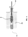
- Each lateral channel 12, 12 ′ is curvilinear and internally sheathed with a stainless steel guide tube 15, connected to a bore 13 (converging in the direction of movement of the wire 11) formed in the projection 9 of the wall of the interior space of the die 1.
- the projection 9 comprises in the axial direction a pointed part 19 at its end, in order to precisely position the wire in the wall of the pipe (see Figure 4).
- the guide tube 15 obviously has an internal diameter adapted to the dimension of the wire 11 which it is intended to guide, as well as bore 13.
Landscapes
- Engineering & Computer Science (AREA)
- Mechanical Engineering (AREA)
- General Engineering & Computer Science (AREA)
- Extrusion Moulding Of Plastics Or The Like (AREA)
- Rigid Pipes And Flexible Pipes (AREA)
Applications Claiming Priority (3)
| Application Number | Priority Date | Filing Date | Title |
|---|---|---|---|
| BE9401035A BE1008956A3 (fr) | 1994-11-17 | 1994-11-17 | Procede de fabrication d'un tuyau a base de matiere plastique, filiere d'extrusion et tuyau. |
| BE9401035 | 1994-11-17 | ||
| PCT/EP1995/004403 WO1996015894A1 (fr) | 1994-11-17 | 1995-11-08 | Procede de fabrication d'un tuyau a base de matiere plastique, filiere d'extrusion et tuyau |
Publications (2)
| Publication Number | Publication Date |
|---|---|
| EP0792206A1 EP0792206A1 (fr) | 1997-09-03 |
| EP0792206B1 true EP0792206B1 (fr) | 1999-03-03 |
Family
ID=3888479
Family Applications (1)
| Application Number | Title | Priority Date | Filing Date |
|---|---|---|---|
| EP95939244A Expired - Lifetime EP0792206B1 (fr) | 1994-11-17 | 1995-11-08 | Procede de fabrication d'un tuyau a base de matiere plastique, filiere d'extrusion et tuyau |
Country Status (12)
| Country | Link |
|---|---|
| EP (1) | EP0792206B1 (da) |
| AT (1) | ATE177048T1 (da) |
| AU (1) | AU4115196A (da) |
| BE (1) | BE1008956A3 (da) |
| CZ (1) | CZ150697A3 (da) |
| DE (1) | DE69508105T2 (da) |
| DK (1) | DK0792206T3 (da) |
| ES (1) | ES2128105T3 (da) |
| GR (1) | GR3030305T3 (da) |
| HU (1) | HU218838B (da) |
| PL (1) | PL178769B1 (da) |
| WO (1) | WO1996015894A1 (da) |
Cited By (1)
| Publication number | Priority date | Publication date | Assignee | Title |
|---|---|---|---|---|
| US20220297364A1 (en) * | 2019-09-18 | 2022-09-22 | Foshan Eahison Communication Co., Ltd. | Dielectric material and dielectric material production method |
Families Citing this family (7)
| Publication number | Priority date | Publication date | Assignee | Title |
|---|---|---|---|---|
| US8497425B2 (en) | 2001-11-20 | 2013-07-30 | Commscope, Inc. Of North Carolina | Toneable conduit with heat treated tone wire |
| US20030094298A1 (en) | 2001-11-20 | 2003-05-22 | Commscope Properties, Llc | Toneable conduit and method of preparing same |
| US7361835B2 (en) | 2001-11-20 | 2008-04-22 | Commscope, Inc. Of North America | Toneable conduit and method of preparing same |
| WO2004094207A1 (en) * | 2003-04-23 | 2004-11-04 | Eus System Ab | Arrangement for a washer system for vehicles and a method for its production |
| EP1774624A1 (en) | 2004-07-07 | 2007-04-18 | Molex Incorporated | Keyed housing for use with small size plug connectors |
| US7880087B2 (en) | 2008-06-23 | 2011-02-01 | Commscope, Inc. Of North Carolina | Toneable conduit with loose toning signal wire |
| US8993888B2 (en) | 2012-10-29 | 2015-03-31 | Commscope, Inc. Of North Carolina | Toneable conduit optimized for conduit shrinkage and elongation |
Family Cites Families (5)
| Publication number | Priority date | Publication date | Assignee | Title |
|---|---|---|---|---|
| DE2248441A1 (de) * | 1972-10-03 | 1974-04-11 | Hans Bergemann | Plastikrohre mit metalleiter zur ortung verlegter plastikrohre |
| US4277432A (en) * | 1979-10-30 | 1981-07-07 | Vesta, Inc. | Method for extruding catheter tubing |
| EP0159307B1 (de) * | 1984-03-20 | 1990-05-02 | Kabelwerk Eupen AG Cablerie d'Eupen SA Kabelfabriek Eupen NV | Verfahren zum Aufbringen eines elektrisch leitfähigen Drahtes auf ein Kabelschutzrohr |
| FR2579926A1 (en) * | 1985-04-03 | 1986-10-10 | Legeais Joseph | Method for producing a reinforced profile made from extruded thermoplastic material, machine for the implementation of this method and resulting product |
| ZA872767B (en) * | 1986-05-08 | 1987-11-25 | Atlas Powder Co | Fuse tube with reinforcing element |
-
1994
- 1994-11-17 BE BE9401035A patent/BE1008956A3/fr not_active IP Right Cessation
-
1995
- 1995-11-08 DK DK95939244T patent/DK0792206T3/da active
- 1995-11-08 HU HU9701840A patent/HU218838B/hu not_active IP Right Cessation
- 1995-11-08 ES ES95939244T patent/ES2128105T3/es not_active Expired - Lifetime
- 1995-11-08 PL PL95320116A patent/PL178769B1/pl unknown
- 1995-11-08 AU AU41151/96A patent/AU4115196A/en not_active Abandoned
- 1995-11-08 CZ CZ971506A patent/CZ150697A3/cs unknown
- 1995-11-08 DE DE69508105T patent/DE69508105T2/de not_active Expired - Fee Related
- 1995-11-08 WO PCT/EP1995/004403 patent/WO1996015894A1/fr not_active Ceased
- 1995-11-08 EP EP95939244A patent/EP0792206B1/fr not_active Expired - Lifetime
- 1995-11-08 AT AT95939244T patent/ATE177048T1/de not_active IP Right Cessation
-
1999
- 1999-05-21 GR GR990401391T patent/GR3030305T3/el unknown
Cited By (2)
| Publication number | Priority date | Publication date | Assignee | Title |
|---|---|---|---|---|
| US20220297364A1 (en) * | 2019-09-18 | 2022-09-22 | Foshan Eahison Communication Co., Ltd. | Dielectric material and dielectric material production method |
| US11890799B2 (en) * | 2019-09-18 | 2024-02-06 | Foshan Eahison Communication Co., Ltd. | Dielectric material and dielectric material production method |
Also Published As
| Publication number | Publication date |
|---|---|
| AU4115196A (en) | 1996-06-17 |
| PL178769B1 (pl) | 2000-06-30 |
| DK0792206T3 (da) | 1999-10-04 |
| HUT77191A (hu) | 1998-03-02 |
| DE69508105T2 (de) | 1999-11-11 |
| CZ150697A3 (en) | 1997-11-12 |
| EP0792206A1 (fr) | 1997-09-03 |
| WO1996015894A1 (fr) | 1996-05-30 |
| BE1008956A3 (fr) | 1996-10-01 |
| ATE177048T1 (de) | 1999-03-15 |
| PL320116A1 (en) | 1997-09-15 |
| GR3030305T3 (en) | 1999-09-30 |
| ES2128105T3 (es) | 1999-05-01 |
| DE69508105D1 (de) | 1999-04-08 |
| HU218838B (hu) | 2000-12-28 |
Similar Documents
| Publication | Publication Date | Title |
|---|---|---|
| CA2947785C (fr) | Conduite flexible non liee de transport d'un materiau abrasif, procede et utilisation associes | |
| EP3105484B1 (fr) | Conduite flexible de transport de fluide munie d'un insert en forme de s étendu et procédé de fabrication associé | |
| CA2297763C (fr) | Conduit flexible, par exemple tuyau a usage medical ou chirurgical | |
| EP0792206B1 (fr) | Procede de fabrication d'un tuyau a base de matiere plastique, filiere d'extrusion et tuyau | |
| FR2660790A1 (fr) | Cable profile pour mise en place dans une conduite de grande longueur. | |
| FR2955371A1 (fr) | Embout de connexion d'une conduite tubulaire flexible pour le transport d'un fluide en milieu marin et procede de montage d'un tel embout de connexion. | |
| FR2743614A1 (fr) | Canalisation flexible | |
| EP0503364A1 (fr) | Procédé de fabrication des tubes en matériaux thermoplastiques renforcés par des fibres à orientation contrôlée et appareillage pour sa mise en oeuvre | |
| EP2528723B1 (fr) | Outillage d'extrusion pour la fabrication de profiles en matiere plastique et procede de mise en oeuvre | |
| EP0025971A1 (fr) | Machine de fabrication en continu de tubes en matière plastique par enroulement hélicoidal | |
| WO1994024595A1 (fr) | Installation et procede de fabrication d'un cable a fibre optique | |
| AU2050399A (en) | Process for the manufacture of an optical core for a telecommunications cable | |
| FR2588352A1 (fr) | Tuyau en beton a chemisage interne en matiere plastique et procede de realisation d'un tel tuyau | |
| EP1010930A1 (fr) | Flexible composite pour le transport de fluide et son procédé de fabrication | |
| EP0055980A2 (fr) | Conduites pour câbles ou éléments similaires, comportant des moyens incorporés de guidage pour ceux-ci | |
| EP3899339B1 (fr) | Conduite flexible pour le transport d'un fluide en milieu sous-marin et procédé associé | |
| FR2719700A1 (fr) | Câble de télécommunications et dispositif pour pousser ce câble dans une conduite. | |
| EP4321322A1 (fr) | Extrudeuse pour l'extrusion d'une couche électriquement isolante comprenant un fourreau ayant un canal d'injection de liquide | |
| EP0884516B1 (fr) | Tube en matière plastique, en particulier destiné à servir de gaine pour le passage de cables ou de canalisations, et couronne d'un tel tube | |
| BE875898R (fr) | Joint pour tuyaux thermoplastiques a parois multiples et procede pour sa production | |
| BE1008710A3 (fr) | Moyens et procede d'application d'une couche de finition de matiere plastique a la surface d'un tuyau; tuyau revetu. | |
| EP2548710B1 (fr) | Procédé de fabrication d'un micro-tube | |
| FR2795879A1 (fr) | Conduit annele en matiere synthetique pre-lubrifie, et procede et installation pour sa realisation | |
| FR2690095A1 (fr) | Procédé de fabrication d'une enveloppe tubulaire métallique et enveloppe obtenue selon ce procédé. | |
| FR2656405A1 (fr) | Element tubulaire a surface exterieure renflee. |
Legal Events
| Date | Code | Title | Description |
|---|---|---|---|
| PUAI | Public reference made under article 153(3) epc to a published international application that has entered the european phase |
Free format text: ORIGINAL CODE: 0009012 |
|
| 17P | Request for examination filed |
Effective date: 19970520 |
|
| AK | Designated contracting states |
Kind code of ref document: A1 Designated state(s): AT BE CH DE DK ES FR GB GR IE IT LI LU MC NL PT SE |
|
| GRAG | Despatch of communication of intention to grant |
Free format text: ORIGINAL CODE: EPIDOS AGRA |
|
| 17Q | First examination report despatched |
Effective date: 19980122 |
|
| GRAG | Despatch of communication of intention to grant |
Free format text: ORIGINAL CODE: EPIDOS AGRA |
|
| GRAH | Despatch of communication of intention to grant a patent |
Free format text: ORIGINAL CODE: EPIDOS IGRA |
|
| GRAH | Despatch of communication of intention to grant a patent |
Free format text: ORIGINAL CODE: EPIDOS IGRA |
|
| GRAA | (expected) grant |
Free format text: ORIGINAL CODE: 0009210 |
|
| AK | Designated contracting states |
Kind code of ref document: B1 Designated state(s): AT BE CH DE DK ES FR GB GR IE IT LI LU MC NL PT SE |
|
| REF | Corresponds to: |
Ref document number: 177048 Country of ref document: AT Date of ref document: 19990315 Kind code of ref document: T |
|
| ITF | It: translation for a ep patent filed | ||
| REG | Reference to a national code |
Ref country code: CH Ref legal event code: EP |
|
| REG | Reference to a national code |
Ref country code: IE Ref legal event code: FG4D Free format text: FRENCH |
|
| GBT | Gb: translation of ep patent filed (gb section 77(6)(a)/1977) |
Effective date: 19990304 |
|
| REF | Corresponds to: |
Ref document number: 69508105 Country of ref document: DE Date of ref document: 19990408 |
|
| REG | Reference to a national code |
Ref country code: ES Ref legal event code: FG2A Ref document number: 2128105 Country of ref document: ES Kind code of ref document: T3 |
|
| REG | Reference to a national code |
Ref country code: PT Ref legal event code: SC4A Free format text: AVAILABILITY OF NATIONAL TRANSLATION Effective date: 19990310 |
|
| REG | Reference to a national code |
Ref country code: DK Ref legal event code: T3 |
|
| PLBE | No opposition filed within time limit |
Free format text: ORIGINAL CODE: 0009261 |
|
| STAA | Information on the status of an ep patent application or granted ep patent |
Free format text: STATUS: NO OPPOSITION FILED WITHIN TIME LIMIT |
|
| 26N | No opposition filed | ||
| PGFP | Annual fee paid to national office [announced via postgrant information from national office to epo] |
Ref country code: IE Payment date: 20001020 Year of fee payment: 6 |
|
| PGFP | Annual fee paid to national office [announced via postgrant information from national office to epo] |
Ref country code: DK Payment date: 20001021 Year of fee payment: 6 |
|
| PGFP | Annual fee paid to national office [announced via postgrant information from national office to epo] |
Ref country code: PT Payment date: 20001023 Year of fee payment: 6 |
|
| PGFP | Annual fee paid to national office [announced via postgrant information from national office to epo] |
Ref country code: MC Payment date: 20001025 Year of fee payment: 6 |
|
| PGFP | Annual fee paid to national office [announced via postgrant information from national office to epo] |
Ref country code: GR Payment date: 20001115 Year of fee payment: 6 |
|
| PGFP | Annual fee paid to national office [announced via postgrant information from national office to epo] |
Ref country code: ES Payment date: 20001116 Year of fee payment: 6 |
|
| PGFP | Annual fee paid to national office [announced via postgrant information from national office to epo] |
Ref country code: GB Payment date: 20001117 Year of fee payment: 6 |
|
| PGFP | Annual fee paid to national office [announced via postgrant information from national office to epo] |
Ref country code: FR Payment date: 20001121 Year of fee payment: 6 |
|
| PGFP | Annual fee paid to national office [announced via postgrant information from national office to epo] |
Ref country code: AT Payment date: 20001122 Year of fee payment: 6 |
|
| PGFP | Annual fee paid to national office [announced via postgrant information from national office to epo] |
Ref country code: BE Payment date: 20001123 Year of fee payment: 6 |
|
| PGFP | Annual fee paid to national office [announced via postgrant information from national office to epo] |
Ref country code: SE Payment date: 20001124 Year of fee payment: 6 Ref country code: LU Payment date: 20001124 Year of fee payment: 6 |
|
| PGFP | Annual fee paid to national office [announced via postgrant information from national office to epo] |
Ref country code: CH Payment date: 20001128 Year of fee payment: 6 |
|
| PGFP | Annual fee paid to national office [announced via postgrant information from national office to epo] |
Ref country code: NL Payment date: 20001130 Year of fee payment: 6 |
|
| PGFP | Annual fee paid to national office [announced via postgrant information from national office to epo] |
Ref country code: DE Payment date: 20001211 Year of fee payment: 6 |
|
| PG25 | Lapsed in a contracting state [announced via postgrant information from national office to epo] |
Ref country code: MC Free format text: LAPSE BECAUSE OF NON-PAYMENT OF DUE FEES Effective date: 20011108 Ref country code: LU Free format text: LAPSE BECAUSE OF NON-PAYMENT OF DUE FEES Effective date: 20011108 Ref country code: IE Free format text: LAPSE BECAUSE OF FAILURE TO SUBMIT A TRANSLATION OF THE DESCRIPTION OR TO PAY THE FEE WITHIN THE PRESCRIBED TIME-LIMIT Effective date: 20011108 Ref country code: GB Free format text: LAPSE BECAUSE OF NON-PAYMENT OF DUE FEES Effective date: 20011108 Ref country code: DK Free format text: LAPSE BECAUSE OF NON-PAYMENT OF DUE FEES Effective date: 20011108 Ref country code: AT Free format text: LAPSE BECAUSE OF NON-PAYMENT OF DUE FEES Effective date: 20011108 |
|
| PG25 | Lapsed in a contracting state [announced via postgrant information from national office to epo] |
Ref country code: SE Free format text: LAPSE BECAUSE OF NON-PAYMENT OF DUE FEES Effective date: 20011109 Ref country code: ES Free format text: LAPSE BECAUSE OF NON-PAYMENT OF DUE FEES Effective date: 20011109 |
|
| PG25 | Lapsed in a contracting state [announced via postgrant information from national office to epo] |
Ref country code: LI Free format text: LAPSE BECAUSE OF NON-PAYMENT OF DUE FEES Effective date: 20011130 Ref country code: CH Free format text: LAPSE BECAUSE OF NON-PAYMENT OF DUE FEES Effective date: 20011130 Ref country code: BE Free format text: LAPSE BECAUSE OF NON-PAYMENT OF DUE FEES Effective date: 20011130 |
|
| REG | Reference to a national code |
Ref country code: GB Ref legal event code: IF02 |
|
| BERE | Be: lapsed |
Owner name: POLVA PIPELIFE B.V. Effective date: 20011130 |
|
| PG25 | Lapsed in a contracting state [announced via postgrant information from national office to epo] |
Ref country code: PT Free format text: LAPSE BECAUSE OF NON-PAYMENT OF DUE FEES Effective date: 20020531 |
|
| PG25 | Lapsed in a contracting state [announced via postgrant information from national office to epo] |
Ref country code: NL Free format text: LAPSE BECAUSE OF NON-PAYMENT OF DUE FEES Effective date: 20020601 |
|
| PG25 | Lapsed in a contracting state [announced via postgrant information from national office to epo] |
Ref country code: GR Free format text: LAPSE BECAUSE OF NON-PAYMENT OF DUE FEES Effective date: 20020610 |
|
| GBPC | Gb: european patent ceased through non-payment of renewal fee |
Effective date: 20011108 |
|
| EUG | Se: european patent has lapsed |
Ref document number: 95939244.0 |
|
| PG25 | Lapsed in a contracting state [announced via postgrant information from national office to epo] |
Ref country code: DE Free format text: LAPSE BECAUSE OF NON-PAYMENT OF DUE FEES Effective date: 20020702 |
|
| REG | Reference to a national code |
Ref country code: CH Ref legal event code: PL |
|
| REG | Reference to a national code |
Ref country code: DK Ref legal event code: EBP |
|
| PG25 | Lapsed in a contracting state [announced via postgrant information from national office to epo] |
Ref country code: FR Free format text: LAPSE BECAUSE OF NON-PAYMENT OF DUE FEES Effective date: 20020730 |
|
| NLV4 | Nl: lapsed or anulled due to non-payment of the annual fee |
Effective date: 20020601 |
|
| REG | Reference to a national code |
Ref country code: FR Ref legal event code: ST |
|
| REG | Reference to a national code |
Ref country code: IE Ref legal event code: MM4A |
|
| REG | Reference to a national code |
Ref country code: FR Ref legal event code: ST |
|
| REG | Reference to a national code |
Ref country code: PT Ref legal event code: MM4A Free format text: LAPSE DUE TO NON-PAYMENT OF FEES Effective date: 20020531 |
|
| REG | Reference to a national code |
Ref country code: ES Ref legal event code: FD2A Effective date: 20021213 |
|
| PG25 | Lapsed in a contracting state [announced via postgrant information from national office to epo] |
Ref country code: IT Free format text: LAPSE BECAUSE OF NON-PAYMENT OF DUE FEES;WARNING: LAPSES OF ITALIAN PATENTS WITH EFFECTIVE DATE BEFORE 2007 MAY HAVE OCCURRED AT ANY TIME BEFORE 2007. THE CORRECT EFFECTIVE DATE MAY BE DIFFERENT FROM THE ONE RECORDED. Effective date: 20051108 |