EP0792576B1 - Schneidvorrichtung für Halm-und Blattgut - Google Patents
Schneidvorrichtung für Halm-und Blattgut Download PDFInfo
- Publication number
- EP0792576B1 EP0792576B1 EP97102739A EP97102739A EP0792576B1 EP 0792576 B1 EP0792576 B1 EP 0792576B1 EP 97102739 A EP97102739 A EP 97102739A EP 97102739 A EP97102739 A EP 97102739A EP 0792576 B1 EP0792576 B1 EP 0792576B1
- Authority
- EP
- European Patent Office
- Prior art keywords
- cutter according
- rings
- bearing
- cutting blades
- notch
- Prior art date
- Legal status (The legal status is an assumption and is not a legal conclusion. Google has not performed a legal analysis and makes no representation as to the accuracy of the status listed.)
- Expired - Lifetime
Links
- 239000004459 forage Substances 0.000 title 1
- 241001124569 Lycaenidae Species 0.000 claims 1
- 238000003825 pressing Methods 0.000 abstract description 2
- 230000006378 damage Effects 0.000 description 2
- 238000000034 method Methods 0.000 description 2
- 230000000712 assembly Effects 0.000 description 1
- 238000000429 assembly Methods 0.000 description 1
- 239000000969 carrier Substances 0.000 description 1
- 238000010276 construction Methods 0.000 description 1
Images


Classifications
-
- A—HUMAN NECESSITIES
- A01—AGRICULTURE; FORESTRY; ANIMAL HUSBANDRY; HUNTING; TRAPPING; FISHING
- A01D—HARVESTING; MOWING
- A01D90/00—Vehicles for carrying harvested crops with means for selfloading or unloading
- A01D90/02—Loading means
- A01D90/04—Loading means with additional cutting means
-
- A—HUMAN NECESSITIES
- A01—AGRICULTURE; FORESTRY; ANIMAL HUSBANDRY; HUNTING; TRAPPING; FISHING
- A01F—PROCESSING OF HARVESTED PRODUCE; HAY OR STRAW PRESSES; DEVICES FOR STORING AGRICULTURAL OR HORTICULTURAL PRODUCE
- A01F15/00—Baling presses for straw, hay or the like
- A01F15/08—Details
- A01F15/10—Feeding devices for the crop material e.g. precompression devices
-
- A—HUMAN NECESSITIES
- A01—AGRICULTURE; FORESTRY; ANIMAL HUSBANDRY; HUNTING; TRAPPING; FISHING
- A01F—PROCESSING OF HARVESTED PRODUCE; HAY OR STRAW PRESSES; DEVICES FOR STORING AGRICULTURAL OR HORTICULTURAL PRODUCE
- A01F15/00—Baling presses for straw, hay or the like
- A01F15/08—Details
- A01F15/10—Feeding devices for the crop material e.g. precompression devices
- A01F2015/107—Means for withdrawing knives, rotor or walls of the feeding chamber in case of plugging or congestion
-
- A—HUMAN NECESSITIES
- A01—AGRICULTURE; FORESTRY; ANIMAL HUSBANDRY; HUNTING; TRAPPING; FISHING
- A01F—PROCESSING OF HARVESTED PRODUCE; HAY OR STRAW PRESSES; DEVICES FOR STORING AGRICULTURAL OR HORTICULTURAL PRODUCE
- A01F15/00—Baling presses for straw, hay or the like
- A01F15/08—Details
- A01F15/10—Feeding devices for the crop material e.g. precompression devices
- A01F2015/108—Cutting devices comprising cutter and counter-cutter
Definitions
- the invention relates to a cutting device for stalks and leaves in the Embodiment according to the preamble of claim 1.
- the previously known cutting devices are designed so that the force that acts on the response threshold of the cutting knife, essentially from Point of attack of the foreign body depends.
- a cutting mechanism of this type is known, for example, from EP 0 204 719 or 100-A-8602802.
- the cutting knife with fasteners on one Crossbar attached, which forms a part of the chassis Axle is pivotally arranged on the front of a loading wagon and the Swiveling the cutting knife in or out of the press channel. All cutting knives are simultaneously locked or released by a profiled cross shaft. A foreign body or overload protection for each individual knife is here not given.
- the present invention has for its object a cutting device with individually secured, quickly replaceable cutting knives create that in its essential parts on a swiveling axis behind the baling channel is arranged and also indicates to the operator that a or several cutting knives are swung out of the working position. At the swung out cutting knives give this version a Foreign matter so free that damage from the press channel Swung-out knife blades did not take place and the cutting edge was preserved remains.
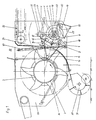
- the Cutting knives 11 are on the support tube 4) of an axis 3) with fixed, centric bearing rings 5), attachable to rotatable outer rings 6) appropriate.
- the outer rings 6) with their inner diameter on the outer diameter the bearing rings 5) are rotatably mounted, wear firmly attached on both sides plate-shaped knife carriers 7), which give lateral guidance and one Bolt 14), under which the contact surface 40) of the symmetrical cutting knife 11) is pivoted.
- Another bolt 15) takes the thrust and Torque forces of the cutting knife 11) above that with bevels provided slot 41).
- a lever 17) is mounted in the joint 16) locks the cutting knife 11), which is with its circular arc Contact surface 42) is supported on the outer diameter of the outer ring 6).
- the Lever 17) is countered by a return spring 18) with the stop surface 45) the contact surface 40) is pressed, with the cutting blades 11) disassembled Support via system 46).
- the outer ring 6) has the notches 9) and 10), one of them snaps into these notches a lever 21) carried roller 19).
- a Tension spring 22) between lever 21) and a plate 8) causes a constant Rest of the roller 19) on the outer ring 6).
- the notch 9) is shaped as a response threshold that at one certain pressure against a cutting knife 11) before the destruction of parts, the roller 19) against the tension of the tension spring 22) leaves the notch 9).
- the Load rotates the cutting knife 11) with the outer ring 6) stationary support tube 4) until it presses u. Has left conveyor channel 1), so that it cannot fall behind when the goods are conveyed unevenly. jumps the Roll 19) in the notch 10) of the outer ring 6).
- the cutting knife 11) is here pivoted from the working position A) into a position B) (see FIG. 2).
- the pivoting process has a spring 24) against a stop surface 43) Knife holder 7) pulled stop bracket 23), pivoting about the axis 3), joined by the pressure of the knife holder 7), this becomes a signal transmitter 25) released, which is now a preferably electrical signal to the Operator station directs where it is immediately recognized that at least one cutting knife 11) has left work situation A).
- At least one lever 48) which is fixedly connected to the support tube 4) and this is pivoted via a double-acting hydraulic cylinder 47), the lever 48) moved from position D) to position E).
- the assembly or disassembly of the cutting knife 11) is best done in the Position C), via the release by lever 17).
Landscapes
- Life Sciences & Earth Sciences (AREA)
- Environmental Sciences (AREA)
- Threshing Machine Elements (AREA)
- Medicines Containing Plant Substances (AREA)
- Apparatuses For Bulk Treatment Of Fruits And Vegetables And Apparatuses For Preparing Feeds (AREA)
Description
Claims (9)
- Schneidvorrichtung für Halm- und Blattgut, die in den Preß- und Förderkanal von Erntemaschinen, wie Ladewagen und Ballenpressen, mit auf einer zur Preßwalze parallelen Achse (3) angeordneten, schwenkbaren Schneidmessern (11) in den Preß- und Förderkanal (1) eingreift, dadurch gekennzeichnet, daß ein mit fest angebrachten Lagerringen (5) versehenes, in Lagern (12) schwenkbares Tragrohr (4), sich quer zur Fahrtrichtung, etwa über die gesamte Breite hinter der Rückwand (13) des Preß- und Förderkanals (1) erstreckt und die Lagerringe (5) mit einzeln herausnehmbaren, einzeln gegen Überlastung gesicherten Schneidmessern (11), welche auf drehbaren Außenringen (6) gelagert sind, trägt.
- Schneidvorrichtung nach Anspruch 1, dadurch gekennzeichnet, daß die Außenringe (6) eine als Ansprechschwelle ausgebildete Kerbe (9) tragen.
- Schneidvorrichtung nach den Ansprüchen 1 u. 2, dadurch gekennzeichnet, daß die Außenringe (6) eine als Halteschwelle ausgebildete Kerbe (10) tragen.
- Schneidvorrichtung nach den Ansprüchen 1 - 3, dadurch gekennzeichnet, daß beidseitig an den Außenringen (6), Messertragplatten (7) fest angeordnet sind, welche mit den Bolzen (14) und (15) und dem im Gelenk (16) scharnierbaren, mit einer Rückstellfeder (18) versehenen Hebel (17), die Schneidmesser (11) zwischen sich tragen.
- Schneidvorrichtung nach den Ansprüchen 1 - 4, dadurch gekennzeichnet, daß der Lagerring (5) beidseitig fest angeordnete Platten (8), zur Aufnahme des mit einer Rolle (19) versehenen, um den Drehpunkt (20) scharnierbaren, mit einer Spannfeder (22) versehenen Hebels (21), trägt.
- Schneidvorrichtung nach den Ansprüchen 1 - 5, dadurch gekennzeichnet, daß die Rolle (19) in der Kerbe (9), in Arbeitsstellung der Schneidmesser (11), anliegt.
- Schneidvorrichtung nach den Ansprüchen 1 - 6, dadurch gekennzeichnet, daß die Rolle (19) in der Kerbe (10), nach dem Ausschwenken eines überlasteten Schneidemessers (11), anliegt.
- Schneidvorrichtung nach den Ansprüchen 1 - 7, dadurch gekennzeichnet, daß ein Signalgeber (25) die Stellung des Anschlagbügels (23) überwacht.
- Schneidvorrichtung nach den Ansprüchen 1 - 8, dadurch gekennzeichent, daß über Hebel (48) das Tragrohr (4) komplett verschwenkbar ist.
Applications Claiming Priority (2)
| Application Number | Priority Date | Filing Date | Title |
|---|---|---|---|
| DE19607915 | 1996-03-01 | ||
| DE1996107915 DE19607915C2 (de) | 1996-03-01 | 1996-03-01 | Schneivorrichtung für Halm- und Blattgut |
Publications (3)
| Publication Number | Publication Date |
|---|---|
| EP0792576A2 EP0792576A2 (de) | 1997-09-03 |
| EP0792576A3 EP0792576A3 (de) | 1999-01-13 |
| EP0792576B1 true EP0792576B1 (de) | 2001-11-14 |
Family
ID=7786933
Family Applications (1)
| Application Number | Title | Priority Date | Filing Date |
|---|---|---|---|
| EP97102739A Expired - Lifetime EP0792576B1 (de) | 1996-03-01 | 1997-02-20 | Schneidvorrichtung für Halm-und Blattgut |
Country Status (3)
| Country | Link |
|---|---|
| EP (1) | EP0792576B1 (de) |
| AT (1) | ATE208557T1 (de) |
| DE (1) | DE59705318D1 (de) |
Families Citing this family (4)
| Publication number | Priority date | Publication date | Assignee | Title |
|---|---|---|---|---|
| ITRM20020430A1 (it) * | 2002-08-14 | 2004-02-15 | Gheon S R L | Dispositivo di taglio di materiale erbaceo o simile |
| PL2540151T3 (pl) * | 2011-06-28 | 2013-10-31 | B Strautmann & Soehne Gmbh & Co Kg | Dwudzielne urządzenie do cięcia łodyg i liści |
| WO2017199341A1 (ja) * | 2016-05-17 | 2017-11-23 | 日本たばこ産業株式会社 | 喫煙物品の製造装置における搬送路近設部品の取付け構造 |
| CN111919606A (zh) * | 2020-08-13 | 2020-11-13 | 安徽科技学院 | 一种用于秸秆堆腐的发酵处理装置 |
Family Cites Families (3)
| Publication number | Priority date | Publication date | Assignee | Title |
|---|---|---|---|---|
| DE9012073U1 (de) * | 1990-08-22 | 1990-10-25 | Schiebelhut, Martin, 6414 Hilders | Silierwagen |
| DE9216457U1 (de) * | 1992-12-03 | 1993-03-18 | Hug, Anton, 7769 Mühlingen | Ladewagen |
| IT1267083B1 (it) * | 1993-12-20 | 1997-01-24 | D B D Spa | Dispositivo di raccolta e taglio di foraggio e paglia |
-
1997
- 1997-02-20 AT AT97102739T patent/ATE208557T1/de active
- 1997-02-20 DE DE59705318T patent/DE59705318D1/de not_active Expired - Lifetime
- 1997-02-20 EP EP97102739A patent/EP0792576B1/de not_active Expired - Lifetime
Also Published As
| Publication number | Publication date |
|---|---|
| EP0792576A2 (de) | 1997-09-03 |
| DE59705318D1 (de) | 2001-12-20 |
| EP0792576A3 (de) | 1999-01-13 |
| ATE208557T1 (de) | 2001-11-15 |
Similar Documents
| Publication | Publication Date | Title |
|---|---|---|
| DE2552805C2 (de) | Erntemaschine, insbesondere Feldhäcksler | |
| BE1027572B1 (de) | Konditionierwalzenzusammenbau | |
| EP3721699B1 (de) | Ballenwickelvorrichtung für eine ballenpresse, beladehilfe und ballenpresse | |
| DE19652656A1 (de) | Verstellvorrichtung für Häckselaggregat | |
| DE2425372A1 (de) | Feldhaecksler | |
| DE19607915C2 (de) | Schneivorrichtung für Halm- und Blattgut | |
| EP0815720A1 (de) | Ballenpresse | |
| EP0153621B1 (de) | Trommelhäcksler mit einer Nachzerkleinerungseinrichtung | |
| AT394126B (de) | Schneidvorrichtung fuer halm- und/oder blattgut | |
| DE2636488A1 (de) | Feldhaecksler | |
| EP0223004A1 (de) | Verfahrbares Zerkleinerungs- und Austragsgerät für Silageblöcke | |
| DE3334045C2 (de) | ||
| EP1797753A2 (de) | Feldhäcksler | |
| DE2220825C2 (de) | Feldhäcksler | |
| EP0792576A2 (de) | Schneidvorrichtung für Halm-und Blattgut | |
| CH664668A5 (de) | Ladewagen mit schleifeinrichtung. | |
| DE19750954A1 (de) | Aufnahmeeinrichtung einer landwirtschaftlichen Erntemaschine | |
| EP1305995B1 (de) | Schwenkvorrichtung für ein mehrteiliges Erntevorsatzgerät | |
| DE19633290A1 (de) | Vorrichtung zur Befestigung und Einstellung der Gegenschneide für Häcksler | |
| EP0014854A1 (de) | Aufnahmevorrichtung für einen Feldhäcksler | |
| DE3324898C2 (de) | ||
| DE3426156C2 (de) | Ladewagen mit einem Trommelförderer | |
| DE2926348C2 (de) | Rollballenaufsammelpresse | |
| DE3215974C2 (de) | Ladewagen | |
| EP4491009B1 (de) | Abladekippvorrichtung und ballenpresse oder wickler |
Legal Events
| Date | Code | Title | Description |
|---|---|---|---|
| PUAI | Public reference made under article 153(3) epc to a published international application that has entered the european phase |
Free format text: ORIGINAL CODE: 0009012 |
|
| AK | Designated contracting states |
Kind code of ref document: A2 Designated state(s): AT DE ES FR IT NL |
|
| PUAL | Search report despatched |
Free format text: ORIGINAL CODE: 0009013 |
|
| AK | Designated contracting states |
Kind code of ref document: A3 Designated state(s): AT DE ES FR IT NL |
|
| 17P | Request for examination filed |
Effective date: 19990505 |
|
| GRAG | Despatch of communication of intention to grant |
Free format text: ORIGINAL CODE: EPIDOS AGRA |
|
| GRAG | Despatch of communication of intention to grant |
Free format text: ORIGINAL CODE: EPIDOS AGRA |
|
| GRAH | Despatch of communication of intention to grant a patent |
Free format text: ORIGINAL CODE: EPIDOS IGRA |
|
| 17Q | First examination report despatched |
Effective date: 20010404 |
|
| GRAH | Despatch of communication of intention to grant a patent |
Free format text: ORIGINAL CODE: EPIDOS IGRA |
|
| GRAA | (expected) grant |
Free format text: ORIGINAL CODE: 0009210 |
|
| AK | Designated contracting states |
Kind code of ref document: B1 Designated state(s): AT DE ES FR IT NL |
|
| PG25 | Lapsed in a contracting state [announced via postgrant information from national office to epo] |
Ref country code: IT Free format text: LAPSE BECAUSE OF FAILURE TO SUBMIT A TRANSLATION OF THE DESCRIPTION OR TO PAY THE FEE WITHIN THE PRESCRIBED TIME-LIMIT;WARNING: LAPSES OF ITALIAN PATENTS WITH EFFECTIVE DATE BEFORE 2007 MAY HAVE OCCURRED AT ANY TIME BEFORE 2007. THE CORRECT EFFECTIVE DATE MAY BE DIFFERENT FROM THE ONE RECORDED. Effective date: 20011114 Ref country code: FR Free format text: LAPSE BECAUSE OF FAILURE TO SUBMIT A TRANSLATION OF THE DESCRIPTION OR TO PAY THE FEE WITHIN THE PRESCRIBED TIME-LIMIT Effective date: 20011114 |
|
| REF | Corresponds to: |
Ref document number: 208557 Country of ref document: AT Date of ref document: 20011115 Kind code of ref document: T |
|
| REF | Corresponds to: |
Ref document number: 59705318 Country of ref document: DE Date of ref document: 20011220 |
|
| PG25 | Lapsed in a contracting state [announced via postgrant information from national office to epo] |
Ref country code: ES Free format text: LAPSE BECAUSE OF FAILURE TO SUBMIT A TRANSLATION OF THE DESCRIPTION OR TO PAY THE FEE WITHIN THE PRESCRIBED TIME-LIMIT Effective date: 20020530 |
|
| PLBE | No opposition filed within time limit |
Free format text: ORIGINAL CODE: 0009261 |
|
| STAA | Information on the status of an ep patent application or granted ep patent |
Free format text: STATUS: NO OPPOSITION FILED WITHIN TIME LIMIT |
|
| EN | Fr: translation not filed | ||
| 26N | No opposition filed | ||
| PGFP | Annual fee paid to national office [announced via postgrant information from national office to epo] |
Ref country code: NL Payment date: 20150223 Year of fee payment: 19 |
|
| PGFP | Annual fee paid to national office [announced via postgrant information from national office to epo] |
Ref country code: AT Payment date: 20150218 Year of fee payment: 19 |
|
| REG | Reference to a national code |
Ref country code: DE Ref legal event code: R082 Ref document number: 59705318 Country of ref document: DE Representative=s name: MEISSNER BOLTE PATENTANWAELTE RECHTSANWAELTE P, DE Ref country code: DE Ref legal event code: R082 Ref document number: 59705318 Country of ref document: DE Representative=s name: MEISSNER, BOLTE & PARTNER GBR, DE |
|
| PGFP | Annual fee paid to national office [announced via postgrant information from national office to epo] |
Ref country code: DE Payment date: 20160226 Year of fee payment: 20 |
|
| REG | Reference to a national code |
Ref country code: AT Ref legal event code: MM01 Ref document number: 208557 Country of ref document: AT Kind code of ref document: T Effective date: 20160220 |
|
| REG | Reference to a national code |
Ref country code: NL Ref legal event code: MM Effective date: 20160301 |
|
| PG25 | Lapsed in a contracting state [announced via postgrant information from national office to epo] |
Ref country code: AT Free format text: LAPSE BECAUSE OF NON-PAYMENT OF DUE FEES Effective date: 20160220 |
|
| PG25 | Lapsed in a contracting state [announced via postgrant information from national office to epo] |
Ref country code: NL Free format text: LAPSE BECAUSE OF NON-PAYMENT OF DUE FEES Effective date: 20160301 |
|
| REG | Reference to a national code |
Ref country code: DE Ref legal event code: R071 Ref document number: 59705318 Country of ref document: DE |