EP0792698A2 - Verfahren und Vorrichtung zur Tauchbeschichtung - Google Patents
Verfahren und Vorrichtung zur Tauchbeschichtung Download PDFInfo
- Publication number
- EP0792698A2 EP0792698A2 EP97301073A EP97301073A EP0792698A2 EP 0792698 A2 EP0792698 A2 EP 0792698A2 EP 97301073 A EP97301073 A EP 97301073A EP 97301073 A EP97301073 A EP 97301073A EP 0792698 A2 EP0792698 A2 EP 0792698A2
- Authority
- EP
- European Patent Office
- Prior art keywords
- coating
- vessel
- drum
- coating material
- insert
- Prior art date
- Legal status (The legal status is an assumption and is not a legal conclusion. Google has not performed a legal analysis and makes no representation as to the accuracy of the status listed.)
- Granted
Links
- 238000000576 coating method Methods 0.000 title claims abstract description 483
- 239000011248 coating agent Substances 0.000 title claims abstract description 466
- 238000000034 method Methods 0.000 title claims abstract description 22
- 230000008569 process Effects 0.000 title claims abstract description 12
- 238000007654 immersion Methods 0.000 title description 3
- 239000000463 material Substances 0.000 claims abstract description 166
- 238000003618 dip coating Methods 0.000 claims abstract description 24
- 239000012530 fluid Substances 0.000 claims abstract description 7
- 230000001105 regulatory effect Effects 0.000 claims abstract description 5
- 239000007788 liquid Substances 0.000 claims description 94
- 238000007789 sealing Methods 0.000 claims description 29
- 239000000049 pigment Substances 0.000 claims description 17
- 239000002245 particle Substances 0.000 claims description 13
- 239000002904 solvent Substances 0.000 claims description 12
- 230000000717 retained effect Effects 0.000 claims description 4
- 229920000642 polymer Polymers 0.000 claims description 3
- 239000010410 layer Substances 0.000 description 74
- 239000000758 substrate Substances 0.000 description 58
- 108091008695 photoreceptors Proteins 0.000 description 30
- 230000007547 defect Effects 0.000 description 28
- 239000011230 binding agent Substances 0.000 description 20
- 239000000243 solution Substances 0.000 description 16
- 230000032258 transport Effects 0.000 description 16
- 239000007787 solid Substances 0.000 description 14
- 239000000203 mixture Substances 0.000 description 13
- 230000000903 blocking effect Effects 0.000 description 11
- 230000008859 change Effects 0.000 description 9
- 238000002474 experimental method Methods 0.000 description 9
- 229910052782 aluminium Inorganic materials 0.000 description 8
- XAGFODPZIPBFFR-UHFFFAOYSA-N aluminium Chemical compound [Al] XAGFODPZIPBFFR-UHFFFAOYSA-N 0.000 description 8
- 238000003384 imaging method Methods 0.000 description 8
- 238000004519 manufacturing process Methods 0.000 description 8
- 239000006185 dispersion Substances 0.000 description 7
- 229910052751 metal Inorganic materials 0.000 description 7
- 239000002184 metal Substances 0.000 description 7
- 239000010935 stainless steel Substances 0.000 description 7
- 229910001220 stainless steel Inorganic materials 0.000 description 7
- YMWUJEATGCHHMB-UHFFFAOYSA-N Dichloromethane Chemical compound ClCCl YMWUJEATGCHHMB-UHFFFAOYSA-N 0.000 description 6
- 239000004809 Teflon Substances 0.000 description 6
- 229920006362 Teflon® Polymers 0.000 description 6
- 230000015572 biosynthetic process Effects 0.000 description 6
- 238000011068 loading method Methods 0.000 description 6
- 239000000523 sample Substances 0.000 description 6
- 230000003213 activating effect Effects 0.000 description 5
- 150000001875 compounds Chemical class 0.000 description 5
- 230000000694 effects Effects 0.000 description 5
- -1 polytetrafluoroethylene Polymers 0.000 description 5
- 229920005989 resin Polymers 0.000 description 5
- 239000011347 resin Substances 0.000 description 5
- 238000012360 testing method Methods 0.000 description 5
- DKPFZGUDAPQIHT-UHFFFAOYSA-N butyl acetate Chemical compound CCCCOC(C)=O DKPFZGUDAPQIHT-UHFFFAOYSA-N 0.000 description 4
- 239000008199 coating composition Substances 0.000 description 4
- 238000012217 deletion Methods 0.000 description 4
- 230000037430 deletion Effects 0.000 description 4
- 238000001035 drying Methods 0.000 description 4
- 229920000728 polyester Polymers 0.000 description 4
- 150000004982 aromatic amines Chemical class 0.000 description 3
- 239000002131 composite material Substances 0.000 description 3
- 238000007796 conventional method Methods 0.000 description 3
- KPUWHANPEXNPJT-UHFFFAOYSA-N disiloxane Chemical class [SiH3]O[SiH3] KPUWHANPEXNPJT-UHFFFAOYSA-N 0.000 description 3
- 229920001971 elastomer Polymers 0.000 description 3
- 239000004033 plastic Substances 0.000 description 3
- 229920003023 plastic Polymers 0.000 description 3
- XLYOFNOQVPJJNP-UHFFFAOYSA-N water Substances O XLYOFNOQVPJJNP-UHFFFAOYSA-N 0.000 description 3
- 239000004677 Nylon Substances 0.000 description 2
- 239000004952 Polyamide Substances 0.000 description 2
- BUGBHKTXTAQXES-UHFFFAOYSA-N Selenium Chemical compound [Se] BUGBHKTXTAQXES-UHFFFAOYSA-N 0.000 description 2
- DHKHKXVYLBGOIT-UHFFFAOYSA-N acetaldehyde Diethyl Acetal Natural products CCOC(C)OCC DHKHKXVYLBGOIT-UHFFFAOYSA-N 0.000 description 2
- 125000002777 acetyl group Chemical class [H]C([H])([H])C(*)=O 0.000 description 2
- JHIVVAPYMSGYDF-UHFFFAOYSA-N cyclohexanone Chemical compound O=C1CCCCC1 JHIVVAPYMSGYDF-UHFFFAOYSA-N 0.000 description 2
- 230000005525 hole transport Effects 0.000 description 2
- 238000003754 machining Methods 0.000 description 2
- 229920001778 nylon Polymers 0.000 description 2
- 239000003973 paint Substances 0.000 description 2
- 229920001084 poly(chloroprene) Polymers 0.000 description 2
- 229920002037 poly(vinyl butyral) polymer Polymers 0.000 description 2
- 229920002647 polyamide Polymers 0.000 description 2
- 239000004417 polycarbonate Substances 0.000 description 2
- 229920000515 polycarbonate Polymers 0.000 description 2
- 229910052711 selenium Inorganic materials 0.000 description 2
- 239000011669 selenium Substances 0.000 description 2
- 239000002356 single layer Substances 0.000 description 2
- AHXBXWOHQZBGFT-UHFFFAOYSA-M 19631-19-7 Chemical compound N1=C(C2=CC=CC=C2C2=NC=3C4=CC=CC=C4C(=N4)N=3)N2[In](Cl)N2C4=C(C=CC=C3)C3=C2N=C2C3=CC=CC=C3C1=N2 AHXBXWOHQZBGFT-UHFFFAOYSA-M 0.000 description 1
- 229910000838 Al alloy Inorganic materials 0.000 description 1
- 229920002449 FKM Polymers 0.000 description 1
- 244000043261 Hevea brasiliensis Species 0.000 description 1
- 229920000459 Nitrile rubber Polymers 0.000 description 1
- 206010067482 No adverse event Diseases 0.000 description 1
- 239000004698 Polyethylene Substances 0.000 description 1
- 239000004743 Polypropylene Substances 0.000 description 1
- 239000004793 Polystyrene Substances 0.000 description 1
- 206010037660 Pyrexia Diseases 0.000 description 1
- 229910001370 Se alloy Inorganic materials 0.000 description 1
- YXFVVABEGXRONW-UHFFFAOYSA-N Toluene Chemical compound CC1=CC=CC=C1 YXFVVABEGXRONW-UHFFFAOYSA-N 0.000 description 1
- 238000005299 abrasion Methods 0.000 description 1
- 239000000654 additive Substances 0.000 description 1
- 230000000996 additive effect Effects 0.000 description 1
- 238000005054 agglomeration Methods 0.000 description 1
- 230000002776 aggregation Effects 0.000 description 1
- 230000004888 barrier function Effects 0.000 description 1
- 238000005452 bending Methods 0.000 description 1
- 238000005422 blasting Methods 0.000 description 1
- 229920005549 butyl rubber Polymers 0.000 description 1
- 238000005266 casting Methods 0.000 description 1
- 238000006243 chemical reaction Methods 0.000 description 1
- MVPPADPHJFYWMZ-UHFFFAOYSA-N chlorobenzene Chemical compound ClC1=CC=CC=C1 MVPPADPHJFYWMZ-UHFFFAOYSA-N 0.000 description 1
- 238000004140 cleaning Methods 0.000 description 1
- 239000011247 coating layer Substances 0.000 description 1
- 239000004020 conductor Substances 0.000 description 1
- 239000002537 cosmetic Substances 0.000 description 1
- 238000000151 deposition Methods 0.000 description 1
- 230000001627 detrimental effect Effects 0.000 description 1
- 238000007598 dipping method Methods 0.000 description 1
- 238000001704 evaporation Methods 0.000 description 1
- 230000008020 evaporation Effects 0.000 description 1
- 238000001914 filtration Methods 0.000 description 1
- 238000005189 flocculation Methods 0.000 description 1
- 230000016615 flocculation Effects 0.000 description 1
- 239000006260 foam Substances 0.000 description 1
- 239000011888 foil Substances 0.000 description 1
- 230000005484 gravity Effects 0.000 description 1
- 238000010438 heat treatment Methods 0.000 description 1
- RBTKNAXYKSUFRK-UHFFFAOYSA-N heliogen blue Chemical compound [Cu].[N-]1C2=C(C=CC=C3)C3=C1N=C([N-]1)C3=CC=CC=C3C1=NC([N-]1)=C(C=CC=C3)C3=C1N=C([N-]1)C3=CC=CC=C3C1=N2 RBTKNAXYKSUFRK-UHFFFAOYSA-N 0.000 description 1
- 230000001771 impaired effect Effects 0.000 description 1
- 238000002347 injection Methods 0.000 description 1
- 239000007924 injection Substances 0.000 description 1
- 238000003780 insertion Methods 0.000 description 1
- 230000037431 insertion Effects 0.000 description 1
- 238000009434 installation Methods 0.000 description 1
- 238000002955 isolation Methods 0.000 description 1
- 238000012423 maintenance Methods 0.000 description 1
- 239000011159 matrix material Substances 0.000 description 1
- 239000012528 membrane Substances 0.000 description 1
- 150000002739 metals Chemical class 0.000 description 1
- 238000000465 moulding Methods 0.000 description 1
- 229920003052 natural elastomer Polymers 0.000 description 1
- 229920001194 natural rubber Polymers 0.000 description 1
- 239000012811 non-conductive material Substances 0.000 description 1
- SJHHDDDGXWOYOE-UHFFFAOYSA-N oxytitamium phthalocyanine Chemical compound [Ti+2]=O.C12=CC=CC=C2C(N=C2[N-]C(C3=CC=CC=C32)=N2)=NC1=NC([C]1C=CC=CC1=1)=NC=1N=C1[C]3C=CC=CC3=C2[N-]1 SJHHDDDGXWOYOE-UHFFFAOYSA-N 0.000 description 1
- YRZZLAGRKZIJJI-UHFFFAOYSA-N oxyvanadium phthalocyanine Chemical compound [V+2]=O.C12=CC=CC=C2C(N=C2[N-]C(C3=CC=CC=C32)=N2)=NC1=NC([C]1C=CC=CC1=1)=NC=1N=C1[C]3C=CC=CC3=C2[N-]1 YRZZLAGRKZIJJI-UHFFFAOYSA-N 0.000 description 1
- 230000002093 peripheral effect Effects 0.000 description 1
- 230000002572 peristaltic effect Effects 0.000 description 1
- 238000009428 plumbing Methods 0.000 description 1
- 229920003227 poly(N-vinyl carbazole) Polymers 0.000 description 1
- 229920005668 polycarbonate resin Polymers 0.000 description 1
- 239000004431 polycarbonate resin Substances 0.000 description 1
- 229920000573 polyethylene Polymers 0.000 description 1
- 229920001155 polypropylene Polymers 0.000 description 1
- 229920001296 polysiloxane Polymers 0.000 description 1
- 229920002223 polystyrene Polymers 0.000 description 1
- 229920001343 polytetrafluoroethylene Polymers 0.000 description 1
- 239000004810 polytetrafluoroethylene Substances 0.000 description 1
- 239000004814 polyurethane Substances 0.000 description 1
- 229920002635 polyurethane Polymers 0.000 description 1
- 238000002360 preparation method Methods 0.000 description 1
- 230000002265 prevention Effects 0.000 description 1
- 230000008439 repair process Effects 0.000 description 1
- 238000007788 roughening Methods 0.000 description 1
- 239000004576 sand Substances 0.000 description 1
- 238000005488 sandblasting Methods 0.000 description 1
- 239000003566 sealing material Substances 0.000 description 1
- 238000000926 separation method Methods 0.000 description 1
- 229920002379 silicone rubber Polymers 0.000 description 1
- 239000000126 substance Substances 0.000 description 1
- BFKJFAAPBSQJPD-UHFFFAOYSA-N tetrafluoroethene Chemical compound FC(F)=C(F)F BFKJFAAPBSQJPD-UHFFFAOYSA-N 0.000 description 1
- 230000007704 transition Effects 0.000 description 1
- AAAQKTZKLRYKHR-UHFFFAOYSA-N triphenylmethane Chemical compound C1=CC=CC=C1C(C=1C=CC=CC=1)C1=CC=CC=C1 AAAQKTZKLRYKHR-UHFFFAOYSA-N 0.000 description 1
- 229920000785 ultra high molecular weight polyethylene Polymers 0.000 description 1
- 238000011144 upstream manufacturing Methods 0.000 description 1
- 238000003466 welding Methods 0.000 description 1
Images




Classifications
-
- B—PERFORMING OPERATIONS; TRANSPORTING
- B05—SPRAYING OR ATOMISING IN GENERAL; APPLYING FLUENT MATERIALS TO SURFACES, IN GENERAL
- B05C—APPARATUS FOR APPLYING FLUENT MATERIALS TO SURFACES, IN GENERAL
- B05C3/00—Apparatus in which the work is brought into contact with a bulk quantity of liquid or other fluent material
- B05C3/02—Apparatus in which the work is brought into contact with a bulk quantity of liquid or other fluent material the work being immersed in the liquid or other fluent material
- B05C3/09—Apparatus in which the work is brought into contact with a bulk quantity of liquid or other fluent material the work being immersed in the liquid or other fluent material for treating separate articles
- B05C3/109—Passing liquids or other fluent materials into or through chambers containing stationary articles
Definitions
- the liquid coating material in the bath may be circulated upwardly in the coating vessel from an inlet at the bottom of the coating vessel and allowed to overflow from the bath. If desired, the coating may be continuously fed into the bottom of the coating vessel and allowed to continuously overflow from the coating vessel.
- the overflowing coating liquid may be collect in a vessel and recycled to the coating bath.
- the coating material fed into the coating bath which flows through a feeding inlet into the bath at a certain flow velocity, may agitate the coating liquid in the bath or ripple the liquid surface of the paint when flowing linearly through the feeding inlet into the coating bath, whereby unevenness of the coating may occur.
- uniformity of film thickness contributes largely to electrophotographic characteristics as in the case of a photosensitive layer of an electrophotographic photosensitive member, it is supremely important to remove the unevenness.
- any slight temperature difference between the coating bath and the ambient temperature frequently causes the air enclosed in the drum to expand or evaporation of the solvent in the coating liquid can increase the volume of the gas in the hollow drum thereby causing the formation of a bubble expelled from the lower end of the drum as the drum is withdrawn from the coating bath.
- the coating liquid will be displaced by the bubble as the bubble rises alongside the drum surface. This causes the coating on the surface of the drum to be uneven.
- a coating solution or dispersion is applied to a drum.
- Dispersions usually comprise various components that are applied to a substrate to form a charge generation layer
- the dispersion may form a single layer photoreceptor instead of only a charge generating layer.
- These coating dispersions usually comprise two phases, such as solid pigment particles dispersed in a solution of a film forming binder dissolved in a solvent. This mixture forms a non-ideal dispersion.
- viscosity remains constant regardless of the amount of shear applied to the coating mixture.
- non-ideal coating compositions such as dispersions, viscosity tends to diminish rapidly with shear. Changes in viscosity affect the coating thickness of the deposited coating..
- streaks can occur in the applied coating. These streaks can be seen by the naked eye and are undesirable from the cosmetic and functional points of view. For example, the streaks can cause print deletion in the final toner image on a printed copy, the deletions corresponding in shape to the streak defect on the photoreceptor. These streaks can occur in any of the layers applied to an electrophotographic imaging member but are particularly pronounced in a charge generating layer.
- the streaks may run the length of a drum or part of the length of a drum. The streaks appear as lighter streaks in a dark background or dark streaks in a lighter background. Moreover, these streaks may be branched.
- a typical streak typically has a width between about 0.2 micrometer and about 1 micrometer. Appearance of these streaks is often referred to as "marbling".
- Dip coating of coated or uncoated substrates can also form coatings that are not uniform from one end of the drum to the other. Since the drums are coated with the drum axis maintained in a vertical position, the coatings on dip coated drums are often thicker at the bottom of the drum than at the top of the drum.
- an apparatus for dip coating comprising a drum having an outer surface to be coated, an upper end and a lower end, at least one coating vessel having a bottom, an open top and a cylindrically shaped vertical interior wall having a diameter greater than the diameter of the drum, an inlet at the bottom of the vessel, the inlet adapted to feed flowing coating fluid into the vessel, a mandrel adapted to maintain the outer surface of the drum in a concentric relationship with the vertical interior wall of the cylindrical coating vessel while the drum is immersed in the flowing coating material, the outer surface of the drum being radially spaced from the vertical interior wall of the cylindrical coating vessel, andat least one flow regulating member adapted to maintain laminar flow motion of the coating material as the fluid passes between the outer surface of the drum and the vertical inner wall of the vessel.
- a dip coating process employing the apparatus described above is also provided.
- FIG. 1 is a schematic elevation view of a coating vessel.
- FIG. 2 is a schematic elevation view of the coating vessel shown in FIG. 1 containing a drum substrate which has a small outside diameter relative to the inside diameter of the coating vessel
- FIG. 3 is a schematic elevation view of the coating vessel shown in FIG. 1 containing a drum substrate which has an outside diameter that is only slightly smaller than the inside diameter of the coating vessel
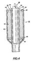
- FIG. 4 is a schematic elevation view of the coating vessel shown in FIG. 1 in combination with an insert, mandrel, and a drum substrate which has an outside diameter that is only slightly smaller than the inside diameter of the insert.
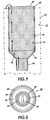
- FIG. 5 is a schematic plan view of the combination shown in FIG. 4.
- FIG. 6 is a schematic elevation view of a coating vessel having a bottom and an insert.
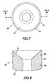
- FIG. 7 is a schematic plan view of the bottom insert of FIG. 6.
- FIG. 8 is a cross sectional schematic elevation view of the bottom insert shown in FIG. 7.
- FIG. 9 is a schematic illustration of a coating system of this invention.
- FIG. 10 is a schematic elevation view of the manifold shown in FIG. 9.
- FIG. 11 is a schematic end view of the manifold shown in FIG. 10.
- a liquid coating material 10 is shown in a coating vessel 12 having a feed inlet 14, inverted funnel shaped bottom 16, vertical cylindrical wall 18 and top edge 20. As indicated by the arrows, the coating material 10 enters coating vessel 12 through feed inlet 14, flows upwardly along an inverted funnel shaped wall 15 and upwardly parallel to vertical cylindrical wall 18, and overflows top edge 20 of vessel 12. The coating material that overflows top edge 20 is captured in a collecting tank 22 (partially shown by phantom lines).
- Drum substrate 23 has an outer diameter that is relatively small compared to the inner diameter of vertical cylindrical wall 18 of coating vessel 12. In other words, the radial spacing between the outer surface of hollow cylindrical drum substrate 23 and the inner surface of vertical cylindrical wall 18 of the coating vessel 12 is very large. This can occur, for example, when a coating operation switches from the coating of large diameter drums to the coating of small diameter drums without changing the coating vessel.
- Drum substrate 23 is suspended from a conventional mandrel 25 which grips the interior surface of drum substrate 23.
- Mandrel 25 also functions as an air tight seal to trap air in the interior of drum substrate 23 when the drum substrate 23 is immersed in the bath of liquid coating material 10 contained in vessel 12.
- drum substrate 23 In dip coating, air trapped within the lower interior space of the hollow drum substrate 23 prevents the liquid coating material 10 from entering and depositing on the interior surface of the substrate 23 and the lower end of the mandrel 25. Usually, a narrow peripheral strip around the top of drum substrate 23 is not submerged in the bath of coating material 10 and remains uncoated.
- the mandrel 25 is connected to conventional transport means which lowers the drum substrate 23 into the bath of liquid coating material 10 and thereafter raises drum substrate 23 from the bath of liquid coating material 10.
- An example of a drum transport device in a dip coating system isillustrated in US-A 4,620,996. Subsequent to withdrawal from the bath of liquid coating material 10 drum substrate 23 carries a thin coating of the material (not shown) from bath 10.
- FIG. 3 a system of this invention is illustrated with hollow cylindrical drum substrate 24 almost totally submerged in liquid coating material 10.
- Hollow cylindrical drum substrate 24 has an outer diameter that is only slightly smaller than the inner diameter of the coating vessel 12.
- the drum substrate 24 should be substantially concentric with the inner surface of vertical cylindrical wall 18 of coating vessel 12 during the coating operation of this invention. It is critical that the radial spacing between the inner surface of vertical cylindrical wall 18 of coating vessel 12 and the outer surface of hollow cylindrical drum substrate 24 during the coating process is between about 2 millimeters and about 9 millimeters in order to adequately avoid streaks and graininess in the final coating.
- the radial spacing is between about 4.5 millimeters and about 8.5 millimeters.
- Optimum coating layers are achieved with an axial spacing between about 5.5 millimeters and about 7.5 millimeters.
- the expression "radial spacing” refers to the spacing between the outer surface of cylindrical drum substrate 23 and the inner surface of vertical cylindrical wall 18 of coating vessel 12 on only one side of the drum along an imaginary radius line
- the “diametric spacing” is twice the size of the "radial spacing” because the diametric spacing includes the spaces on opposite sides of cylindrical drum substrate 23 measured along an imaginary diameter line.
- the diametric spacing is between about 4 millimeters and about 18 millimeters.
- Example 1 of US-A 4,620,996 the radial spacing of the drum to the coating vessel wall is 1 centimeter or 10 millimeters. In Example 2 of US-A 4,620,996, the radial spacing of the drum to the coating vessel wall is 10 millimeters. These radial spacings are about 11 percent greater than the maximum radial spacing of 9 millimeters used in the coating system of this invention.
- FIG. 4 illustrates the coating vessel 12 shown in FIG. 1 in combination with an annular insert 30 and a hollow cylindrical drum substrate 26 which has a relatively small outer diameter compared to the inner diameter of coating vessel 12.
- Drum substrate 26 is suspended by a conventional mandrel 28 which grips the interior surface of drum substrate 26.
- annular insert 30 within the interior of coating vessel 12 enables achievement of a critical spacing between the outer surface of drum substrate 26 and inner surface 32 of vertical wall 33.
- Vertical wall 32 is spaced from, adjacent to and parallel to the outer surface of drum substrate 26.
- Insert 30 may comprise retaining grooves 34 and 36 which retain elastomeric sealing rings 38 and 40, respectively.
- the sealing rings 38 and 40 may be of any suitable shape. However, elastomeric "O" rings are preferred. If desired, additional retaining grooves and sealing rings (not shown) may be utilized.
- the sealing rings 38 and 40 prevent coating material from entering and circulating between insert 30 and the adjacent wall of liquid coating vessel 10. Insert 30 comprises a main insert body 41 and insert sleeve 42. Since coating vessels 12 are normally formed from welded sheet metal, the wall 33 is usually not perfectly straight. For example, the wall 33 may have a slightly wavy shaped inner surface 32 which can hamper achievement of laminar flow of the coating material between the inner surface 32 and the outer surface of drum substrate 26.
- resilient elastomeric sealing rings 38 and 40 retained in grooves 34 and 36 extending circumferentially around the outer periphery of insert 30 near the top and at the bottom thereof, alignment of the insert 30 in coating vessel 12 having an imperfectly shaped wall 33 is more readily achieved due to compensating deformation of resilient elastomeric sealing rings 38 and 40.
- the elastomeric sealing rings 38 and 40 function as a damper to further insulate the insert 30 from external sources of vibration. Any suitable dampening and sealing material may be employed for sealing rings 38 and 40.
- Typical sealing ring materials include, for example, natural rubber, neoprene, butyl rubber, nitrile rubber, silicone elastomer, Viton, Teflon, and the like.
- sealing rings may be utilized between the upper ring 38 and the lower ring 40.
- the sealing rings may have any other suitable cross section. Typical cross sections include, for example, circular, oval, square, octagonal, star, and the like.
- the sealing rings are resilient and have a durometer of between about 30 and about 100.
- Each sealing ring should have sufficient thickness so that it is partially compressed when the insert 30 is installed in the coating vessel 12.
- each sealing ring 38 and 40 has a thickness that is greater than the depth of the retaining grooves 34 and 36, respectively, which circumscribe the outer surface of the insert 30.
- the retaining grooves 34 and 36 may have any suitable cross sectional shape such as, for example, square, rectangular, "V", "U”, semi-circular and the like.
- a retaining groove having a square shaped cross section typically has a width between about 0.2 millimeter and about 1 millimeter and a depth of between about 0.2 micrometer and about 1 millimeter.
- the retaining grooves 38 and 40 are preferably large enough to retain the sealing ring during installation of the insert, after the insert is installed, and during removal from the coating vessel 12. If no sealing rings are employed on the insert body, the liquid coating material 10 can flow between the insert and the coating vessel walls and form undesirable deposits of the coating material 10 on the outer surface of the insert 30 and the inner surface 32 of the coating material vessel 12. These deposits are difficult to remove during cleaning operations following removal of the insert from coating vessel 12.
- the main insert body 41 may comprise any suitable material.
- the insert body is made of a plastic, metal or composites.
- Typical plastics include, for example, polytetrafluoroethylene, nylon, polycarbonate, polyester, UHMW polyethylene or polypropylene. and the like and composites thereof.
- Typical metals include, for example, stainless steel, aluminum, aluminum alloys, and the like and composites thereof.
- Main insert body 41 may be solid, foam filled, hollow or the like. A hollow insert body is preferred to reduce weight and to conserve materials.
- the main insert body may be fabricated by any suitable means such as molding, machining, casting, and the like. The material utilized for the main insert body 41 should not be degradable by the materials employed for coating the drum 26.
- insert sleeve 42 extends beyond the top surface 44 of the main insert body 41.
- This extension of sleeve 42 is preferably thin to isolate the coating being formed on the surface of the drum substrate 26 from ripples formed in the large pool of coating material on top surface 44 flowing away from sleeve 42.
- the extension of sleeve 42 also facilitates alignment of the the upper surface of the sleeve 42 with the upper surface of other like sleeves of other coating vessels in the same coating system so that the amount of overflow out of sleeve 42 is substantially the same for all like sleeves in the same coating system.
- Insert sleeve 42 may comprise any suitable material such as metal or plastic.
- Sleeve 42 preferably comprises a metal because it can be readily fabricated to form a smooth long life surface, such as by machining, to facilitate alignment of the top of sleeve 42 with the tops of other sleeves in the same coating system and to promote laminar flow of coating material 10 as it overflows from the sleeve 42.
- a metal because it can be readily fabricated to form a smooth long life surface, such as by machining, to facilitate alignment of the top of sleeve 42 with the tops of other sleeves in the same coating system and to promote laminar flow of coating material 10 as it overflows from the sleeve 42.
- an insert sleeve facilitates alignment of the tops of each sleeve at the same level as the other sleeves in the coating system so that the flow of liquid coating material is smooth and uniform around the periphery of each drum.
- the insert sleeve 42 may be omitted, superior quality coatings are achieved when the sleeve 42 is utilized in an insert.
- the flat top surface 44 of main insert body 41 creates a relatively large pool of overflowing coating material 10 which is more vulnerable to the formation of ripples caused by sources of vibrational energy. More specifically, vibrational disturbances cause ripples much like the ring shaped ripples that form when a pebble is dropped onto the calm surface of a pond. These ripples propagate in two directions.
- the liquid coating material 10 can flow between the insert and the coating vessel walls and reenter the main coating stream at the top of the vessel to cause ripples to form in the liquid coating material 10 flowing along the top surface 44 of main insert body 41.
- some of these ripples can propagate toward the substrate 26 that is being withdrawn from the bath of coating material 10.
- these ripples can strike and deform the outer surface of the coating carried on the drum 26 while drum 26 is being withdrawn from the bath of coating material 10 to cause deformations in the coating which can still be detected even after the coating has been dried.
- a sleeve 42 and sealing rings 38 and 40 are preferred when using an annular insert 30, they may be omitted with less desirable results.
- Mandrel 28 supports hollow cylindrical drum substrate 26 in liquid coating material 10. Spaced from hollow cylindrical drum substrate 26 is insert sleeve 42 of annular insert 30. Insert 30 is snugly retained within coating vessel 12 by elastomeric sealing rings with only sealing ring 38 seated in being visible.
- Bottom insert 46 that is inserted into a coating vessel 48 having a relatively flat bottom 50 and vertical wall 51.
- Bottom insert 46 aids in the prevention of turbulence in the form of eddies that can develop in the stream of flowing liquid coating material (not shown) as it enters coating vessel 48 through feed inlet 49 and abruptly spreads out along relatively flat bottom 50.
- Bottom insert 46 has a bottom 52 and vertical side 53 which match the shape of the adjacent interior surface of bottom 50 and vertical wall 51, respectively, of coating vessel 48.
- the vertical side 51 of bottom insert 46 contains retaining grooves 54 and 55 which retain elastomeric sealing rings 56 and 57, respectively. If desired, additional retaining grooves elastomeric sealing rings (not shown) may be utilized.
- Bottom insert 46 has an upper surface 59 shaped like an inverted cone. This cone shape forces the liquid coating material to gradually spread outwardly away from the vertical axis of vessel 48 as it flows into the space between the substrate to be coated (not shown) and the vertical wall 51 of coating vessel 48. To install insert 46, one may merely slide it down to the bottom of vessel 46.
- the region in the dip coating vessel 48 below the drum substrate (not shown) at the point of maximum immersion of the drum substrate in the coating material should be sufficiently large to avoid undue restriction of flow and to prevent undesirable turbulence in the coating material as the coating material flows upwardly between the outer surface of the drum and the inner surface of the coating vessel 48 or the inner surface of a coating vessel insert (not shown). Since the relative sizes of the drum, coating vessel, and feed inlet and rate of coating material flow affect the desired size of the region in the dip coating vessel 48 below the drum substrate (not shown) at the point of maximum immersion of the drum substrate, some experimentation is desirable to achieve laminar flow of the coating material in this region.
- the velocity change of the coating material from feed inlet 49 into the low portion of the coating vessel 48 will be too abrupt, laminar flow will be impaired and defects in the coating applied to the drum will occur.
- the feed inlet 49 has a diameter of about 1/2 inch (12 millimeters) and the bottom of the coating vessel 48 has a diameter of about 5 inches (1.25 centimeters)
- the sudden decrease in the velocity of the coating material will disrupt laminar flow and cause coating defects in the final drum coating. This is from about 1/4 : 1 to about 1:1.
- abrupt changes in diameter of the means constraining the coating material as it is fed into the bottom of a coating vessel can also be avoided by integrating a funnel shaped entrance at the bottom of the coating vessel when the vessel is initially fabricated, e.g.. see FIG 1.
- the funnel shape may be achieved, for example, by welding a funnel shaped bottom to the vertical walls of a coating vessel.
- a flat bottom is always detrimental to the stated objective. It is noteworthy that even a shallow angled bottom will always cause eddies to form in the recesses of a tight corner and these eddies will form defects on the coating surface. To avoid this occurence it is necessary to maintain a wide angle where the bottom meets the sides. The optimum angle is 180 degrees.
- a preferred angle is between about 135 and about 160 degrees and a minimum angle is about 120 degrees.
- laminar flow as employed herein is typically understood to represent a flow of liquid where the flow everywhere in all planes of reference is in the same direction and parallel to the surface of the tube and the tank walls. This flow is smooth, even and totally without turbulence in any region of reference or concern, i.e. "streamlined".
- FIGS. 9, 10 and 11n A coating system utilizing eight coating vessels are shown in FIGS. 9, 10 and 11n with only coating vessels 60, 62, 64 and 66 being visible.
- Liquid coating material is fed to these coating vessels through feed lines 68, 70, 72 and 74, respectively, which are connected in turn through elbow fittings 78, 80, 82 and 84, respectively (the other four feed lines and elbow fittings not being visible in FIGS. 7 and 8) to feed manifold 86.
- the coating material not shown, overflows from the coating vessels into collecting tank 88 (shown in phantom lines), it flows by gravity (a pump may optionally be employed) to reservoir 90.
- the liquid coating material is pumped by a suitable pump 92 through a low pressure filter 94 into the tapered inlet 96 of manifold 86.
- All bends in the lines between reservoir 90 and the coating vessels should have a large radius of curvature to maintain laminar flow motion of the liquid coating material prior to introduction into the coating vessels. It is also important that the liquid coating material being delivered to the dip coating vessels 60, 62, 64 and 66 be maintained in laminar flow motion prior to introduction into each coating vessel to ensure laminar flow within each coating vessel and to prevent the formation of defects in the applied coating.
- All feed lines 98 and 99 from reservoir 90 preferably have smooth and electropolished interior surfaces.
- each coating vessel and feed lines 68, 70, 72 and 74, elbow fittings 78, 80, 82 and 8 and manifold 86 should be smooth and free of burrs. Also, all piping should not impart sudden changes of direction or velocity to the liquid coating material, particularly, the manifold which delivers the liquid coating material to the individual coating vessels with no change in relative velocity.
- any bends in the lines between the coating material reservoir 90 and the bottom of each coating vessel 60, 62, 64 and 66 should have large radius turns.
- the radius bend in any line from reservoir 90 to pump 92 should have a radius of at least about 2 inches (5 centimeters).
- All bends in lines connecting pump 92 and filter 94 to the manifold 86 should have a radius of at least about 6 inches (15 centimeters).
- all bends in connecting lines between the manifold 86 and the bottom of each coating vessel 60, 62, 64 and 66 have a radius of at least about 8 inches (20 centimeters).
- the cross-sectional area of manifold 86 should be equal to about the sum of the cross-sectional areas of each of the connecting lines (passageways) between the manifold and the bottom of each coating vessel.
- any valves utilized in the coating system should be free of any components which would restrict the coating material flow during the coating operation.
- Preferred valves which do not restrict flow when opened include. for example, ball valves and plug valves which when open provide exactly the same interior cross section as the incoming and out going connecting lines.
- Undesirable valves which tend to restrict flow even in the open position include, for examples, gate valves, shutter valves, needle valves, and the like.
- a low back pressure filter 94 may be utilized in the main feed line 98 between the manifold and coating material pump.
- the low back pressure filter 98 should be impart a pressure drop of less than about 2 pounds per square inch (0.14 kilograms per square centimeter).
- Typical low back pressure filters comprise a convoluted filter membrane resembling an extensively pleated sheet surrounding an open core. The coating material pumped through this type of filter undergoes essentially zero pressure drop because of the huge area available for filtering.
- pressure in the liquid coating material between the pump 92 and the bottom of each coating vessel is less than about 1 pound per square inch (0.07 kilograms per square centimeter) during the coating cycle. It is is important that the pressure is equal in all directions in the coating material liquid in order to achieve laminar flow in the manifold and in the lines connecting the manifold 86 to the bottom of each coating vessel.
- the dip coating system of this invention transports and recirculates liquid coating material while isolating the coating material from various energy inputs or losses to produce a consistently uniform and defect free coating.
- all sources of heat and vibration should be isolated from the liquid coating material.
- pump motors which generate heat during operation such as gear pumps, are to be avoided because they can cause agglomeration of pigment particles and separation of the dispersion in liquid coating compositions such as coatings for charge generation layers.
- the liquid coating material pump preferably provides uniform delivery of the coating liquid to a manifold and each coating vessel without imparting any significant heat energy to the flowing liquid coating material.
- the pump should be a low shear pump.
- Typical low shear pumps include, for example, sine pumps, auger pumps, centrifugal pumps, oil-less diaphragm pumps (acetal, teflon). Also included are two or three small pumps running out of phase with each other such as peristaltic pumps, sine pumps, auger pumps, centrifugal pumps, oil-less diaphragm pumps (acetal, teflon), and the like.
- a high shear pump such as a gear pump may be utilized if it is positioned far upstream from the manifold and sufficient filters are interposed between the high shear and the manifold to remove agglomerated materials.
- Isolation from vibration can be aided by mounting coating vessels, manifold, feed lines and the like on vibration absorbing means such as rubber pads, springs and elastomeric members.
- Heat exchangers may be utilized to prevent large changes in the temperature of the liquid coating material.
- the total fluctuation or variation in temperature of the coating liquid in the manifold, feed lines between the manifold and the bottom of the coating vessel and in each coating vessel should be maintained at a level of less than about 2°C.
- Temperature fluctuations in the liquid coating material greater than about 2°C. tends to cause streaks to form in the applied coating, particularly in charge generator layers.
- Optimum results are achieve when the total variation in temperature of the liquid coating material is maintained less than about 0.5°C. When temperature fluctuations reach 3°C, the liquid coating material is totally unsatisfactory for forming uniform deposited coatings. Maintenance of temperature fluctuation to less than about 2°C.
- Air flow in the coating environs must also be regulated to less than 1°C. of variation, and direct air flows at the wet surfaces of freshly coated parts should be directed away by means of a shield or an incoming vent which will suitably dissipate the air flow so that it will not impinge and distort any wet coated surface.
- an upward liquid coating material velocity of between about 15 millimeters per minute and about 300 millimeters per minute between the outer surface of the drum and the vertical inner wall of the coating vessel.
- the upward velocity is maintained at between about 100 millimeters per minute and about 200 millimeters per minute. This velocity is measured at the center of, i.e. midway between, the space between the inner vessel and the outer surface of the drum being coated as the drum is being withdrawn from the liquid coating mixture.
- the velocity of the liquid coating material near the inner surface of the coating vessel and the outer surface of the drum are lower than the velocity at the center of the space between the drum and the vessel wall, the flow of the coating material is laminar.
- the center of the space between the drum and the vessel wall intersects an imaginary curved. cylindrically shaped plane that is coaxial with the drum and the adjacent inner surface of the coating vessel.
- Electrostatographic imaging members are well known in the art.
- the electrostatographic imaging member may be prepared by various suitable techniques. Typically, a substrate is provided having an electrically conductive surface. At least one photoconductive layer is then applied to the electrically conductive surface. An optional thin charge blocking layer may be applied to the electrically conductive layer prior to the application of the photoconductive layer.
- a charge generation layer is usually applied onto the blocking layer and charge transport layer is formed on the charge generation layer.
- the photoconductive layer is a photoconductive insulating layer and no separate, distinct charge transport layer is employed.
- any suitable size drum may be coated with the process of this invention.
- Typical drum diameters include, for example, diameters of about 30 millimeters, 40 millimeters, 85 millimeters, and the like.
- the surface of the drum being coated is smooth. However, if desired, it may be slightly roughened by honing, sand blasting, grit blasting, and the like Such slight roughening forms a surface which varies from average diameter by less than about plus or minus 3 micrometers.
- the surface of the drum being coated is preferably inert to the components in the liquid coating material.
- the drum surface may be a bare, uncoated surface or may comprise a previously deposited coating or coatings.
- the substrate may be opaque or transparent and may comprise numerous suitable materials having the required mechanical properties. Accordingly, the substrate may comprise a layer of an electrically non-conductive or conductive material such as an inorganic or an organic composition.
- the electrically insulating or conductive substrate should be rigid and in the form of a hollow cylindrical
- the thickness of the substrate layer depends on numerous factors, including resistance to bending and economical considerations, and thus this layer for a drum may be of substantial thickness, for example, about 5 millimeters, or of minimum thickness such as about 1 millimeter, provided there are no adverse effects on the final electrostatographic device.
- the conductive layer and the substrate may be one and the same or the conductive layer may comprise a coating on the substrate.
- the thickness of the conductive layer may be as thin as about 50 angstroms, and more preferably at least about 100 Angstrom units for optimum electrical conductivity.
- the conductive layer may be an electrically conductive metal layer.
- a hole blocking layer may be applied thereto.
- electron blocking layers for positively charged photoreceptors allow holes from the imaging surface of the photoreceptor to migrate toward the conductive layer.
- Any suitable blocking layer capable of forming an electronic barrier to holes between the adjacent photoconductive layer and the underlying conductive layer may be utilized.
- Typical blocking layers include, for example, polyamides, polyvinylbutyrals, polysiloxanes, polyesters, and the like and mixtures thereof.
- the blocking layer should be continuous and have a thickness of less than about 0.2 micrometer because greater thicknesses may lead to undesirably high residual voltage.
- any suitable photogenerating layer may be applied to the blocking layer.
- typical photogenerating layers include inorganic photoconductive particles such as amorphous selenium, trigonal selenium, selenium alloys and mixtures thereof, and organic metal phthalocyanines such as vanadyl phthalocyanine and copper phthalocyanine, dibromoanthanthrone, squarylium, and quinacridones.
- organic metal phthalocyanines such as vanadyl phthalocyanine and copper phthalocyanine, dibromoanthanthrone, squarylium, and quinacridones.
- Other suitable photogenerating materials known in the art may also be utilized, if desired.
- the average particle size of the pigment dispersed in the charge generating layer is less than about 1 micrometer.
- a preferred average size for pigment particles is between about 0.05 micrometer and about 0.2 micrometer.
- Any suitable polymeric film forming binder material may be employed as the matrix in the photogenerating binder layer.
- Typical polymeric film forming materials include resins such aspolyvinylbutyral, polycarbonates, polyesters, polyamides, polyurethanes, polystyrenes, and mixtures thereof.
- Any suitable solvent may be employed to dissolve the film forming binder.
- a pigment to binder weight ratio of between about 40:60 and about 95:5.
- the pigment to binder ratio is between about 50:50 and about 90:10.
- the thickness of the deposited charge generating layer coating affects various factors affect the thickness of the deposited charge generating layer coating. These factors include, for example, the solids loading of the total liquid coating material, the viscosity of the liquid coating material, and the relative velocity of the liquid coating material in the space between the drum surface and coating vessel wall. Satisfactory results are achieved with a solids loading of between about 2 percent and about 12 percent based on the total weight of the liquid coating material; the "total weight of the solids" being the combined weight of the film forming binder and pigment particles and the “total weight of the liquid coating material” being the combined weight of the film forming binder, the solvent for the binder and pigment particles.
- the liquid coating mixture has a solids loading of between about 3 percent and about 8 percent by weight based on the total weight of the liquid coating material.
- the thickness of the deposited coating varies with the specific solvent, film forming polymer and pigment materials utilized for any given coating composition.
- a relatively slow drum withdrawal (pull) rate is desirable when utilizing high viscosity liquid coating materials.
- the viscosity of the liquid coating material varies with the solids content of the liquid coating material. Satisfactory results may be achieved with viscosities between about 1 centipoise and about 100 centipoises.
- the viscosity is between about 2 centipoises and about 10 centipoises.
- the photogenerating composition or pigment is present in the resinous binder composition in various amounts, generally, however, from about 5 percent by volume to about 90 percent by volume of the photogenerating pigment is dispersed in about 10 percent by volume to about 95 percent by volume of the resinous binder.
- the deposited charge generating layer thickness generally ranges in thickness of from about 0.1 micrometer to about 5 micrometers. Thicknesses outside these ranges can be selected providing the objectives of the present invention are achieved.
- the active charge transport layer may comprise an activating compound useful as an additive dispersed in electrically inactive polymeric materials render these materials electrically active.
- a typical transport layer employed in one of the two electrically operative layers in multilayered photoconductors comprises from about 25 percent to about 75 percent by weight of at least one charge transporting aromatic amine compound, and about 75 percent to about 25 percent by weight of a polymeric film forming resin in which the aromatic amine is soluble.
- Examples of charge transporting aromatic amines represented by the structural formulae above for charge transport layers capable of supporting the injection of photogenerated holes of a charge generating layer and transporting the holes through the charge transport layer include triphenylmethane, bis(4-diethylamine-2-methylphenyl)phenylmethane; 4'-4"-bis(diethylamino)-2',2"-dimethyltriphenylmethane, N,N'-bis(alkylphenyl)-[1,1'-biphenyl]-4,4'-diamine dispersed in an inactive resin binder.
- any suitable inactive resin binder soluble in methylene chloride or other suitable solvent may be employed in the photoreceptor.
- Typical inactive resin binders soluble in methylene chloride include polycarbonate resin, polyvinylcarbazole, and polyester. Molecular weights can vary, for example, from about 20,000 to about 150,000.
- a preferred coating technique utilizes the dip coating system of this invention.
- Various factors affect the thickness of the dip deposited charge transport layer coating. These factors include, for example, the solids loading of the total liquid coating material, the viscosity of the liquid coating material, and the relative velocity of the liquid coating material in the space between the drum surface and coating vessel wall.
- the liquid charge transport layer coating mixture has a solids loading of between about 3 percent and about 6 percent by weight based on the total weight of the liquid coating material.
- the photoreceptors may comprise, for example, a charge generator layer sandwiched between a conductive surface and a charge transport layer as described above or a charge transport layer sandwiched between a conductive surface and a charge generator layer.
- Liquid coating material was pumped from a liquid coating material reservoir tank to the feed inlet pipe by means of a MICRO pump (Model GM - 8, available from Siewert Co.) which pumped the coating material through a PALL filter (Model AB1Y070, available from Prosco Products Co.) and a manifold to the feed inlet pipe in a system similar to that shown in FIGS. 9, 10 and 11.
- the pressure drop across the filter was 5 pounds per square inch (351.5 grams per square centimeter).
- the top of the coating vessel was open.
- the liquid coating material comprised a photogenerating layer (CGL) containing 5.0 percent by weight titanyl phthalocyanine and chloroindium phthalocyanine pigment particles with polyvinyl butyral (B79, available from Monsanto Co.) binder with 95 percent n-butyl acetate as solvent.
- the pigment particles had an average particle size of about 0.2 micrometer.
- This liquid coating material has a viscosity of 10 centipoises.
- the pigment to binder weight ratio was 64 : 36.
- the lower section of the coating vessel had the shape of an inverted cone.
- the uppermost part of the inverted cone section had a diameter equal to the diameter of the cylindrically shaped upper section.
- the lowermost part of the inverted cone section contained an opening having a diameter of 10 millimeters. This opening was connected to a feed inlet pipe having a diameter of 10 millimeters.
- Liquid coating material was pumped from a liquid coating material reservoir tank to the feed inlet pipe by means of a MICRO pump (Model GM-8, available from Siewert Co.) which pumped the coating material through a PALL filter (Model AB1Y070, available from Prosco Products Co.) and a manifold to the feed inlet pipe in a system similar to that shown in FIGS. 9, 10 and 11.
- Table A clearly demonstrates that the insert eliminated streaking whereas streaking was excessive in the absence of the insert.
- This device was held in place by two O - rings of TEFLON encapsulated rubber, which also served to restrict the flow of solution solely to flowing through the cross shaped blade opening.
- This device was machined from stainless steel, but might alternately be fabricated from Teflon, nylon, aluminum or other suitable materials. All conditions of the system were set, before the addition of the "Vortex Breaker,"as previously noted, so as to produce a coating surface on the drum which was free of all defects. A drum was then dipped into the coating vessel as described above with the "Vortex Breaker" in place in the coating vessel. This coating was completely covered with multiple streaks. This experiment demonstrated two major parameters which affect the coating surface quality.
- a drum was then dipped into the coating vessel as described above with the ball valve in place in the coating vessel. This coating was completely free of defects. This result showed that the "ball valve" in and of itself did not introduce any effects to cause defects in the coated surface.
- a drum was then dipped into the coating vessel as described above with the ball valve in place below the coating vessel, and the valve set to a partially closed position, which represented a 75 percent restriction to the normal flow.
- a drum was then dipped into the coating vessel as described above with the ball valve in place in the coating vessel. This coating on the drum was completely covered with multiple streaks. This experiment demonstrated that the obstruction provided by the restriction of the partially closed valve was quite sufficient to induce the necessary shear to cause the the coating material to demonstrate streaking which causes the defect in the drum coating and subsequently on the copy made from the coated drum.
Landscapes
- Coating Apparatus (AREA)
- Photoreceptors In Electrophotography (AREA)
- Application Of Or Painting With Fluid Materials (AREA)
Applications Claiming Priority (4)
| Application Number | Priority Date | Filing Date | Title |
|---|---|---|---|
| US08/609,269 US5681391A (en) | 1996-02-29 | 1996-02-29 | Immersion coating apparatus |
| US08/608,829 US5693372A (en) | 1996-02-29 | 1996-02-29 | Immersion coating process |
| US608829 | 2000-06-30 | ||
| US609269 | 2000-06-30 |
Publications (3)
| Publication Number | Publication Date |
|---|---|
| EP0792698A2 true EP0792698A2 (de) | 1997-09-03 |
| EP0792698A3 EP0792698A3 (de) | 1998-05-27 |
| EP0792698B1 EP0792698B1 (de) | 2004-12-08 |
Family
ID=27085876
Family Applications (1)
| Application Number | Title | Priority Date | Filing Date |
|---|---|---|---|
| EP19970301073 Expired - Lifetime EP0792698B1 (de) | 1996-02-29 | 1997-02-19 | Verfahren und Vorrichtung zur Tauchbeschichtung |
Country Status (3)
| Country | Link |
|---|---|
| EP (1) | EP0792698B1 (de) |
| JP (1) | JPH09244275A (de) |
| DE (1) | DE69731855T2 (de) |
Cited By (1)
| Publication number | Priority date | Publication date | Assignee | Title |
|---|---|---|---|---|
| CN119333575A (zh) * | 2024-12-23 | 2025-01-21 | 常州市迈卡威机械制造有限公司 | 一种减速机输出轴的双层密封装置及密封性检测方法 |
Families Citing this family (6)
| Publication number | Priority date | Publication date | Assignee | Title |
|---|---|---|---|---|
| JP3809397B2 (ja) * | 2002-05-22 | 2006-08-16 | 京セラミタ株式会社 | 感光体の連続塗工方法 |
| US6962626B1 (en) * | 2004-05-28 | 2005-11-08 | Xerox Corporation | Venting assembly for dip coating apparatus and related processes |
| JP4568674B2 (ja) * | 2005-11-07 | 2010-10-27 | 株式会社リコー | 電子写真感光体製造装置及び製造方法 |
| JP2007225679A (ja) * | 2006-02-21 | 2007-09-06 | Ricoh Co Ltd | 塗工装置、感光体の製造方法、感光体、及び画像形成装置 |
| KR102094127B1 (ko) * | 2018-07-31 | 2020-03-27 | 부산대학교 산학협력단 | 딥코팅 장치 및 딥코팅 방법 |
| EP4789854A1 (de) * | 2025-02-05 | 2026-08-12 | Carl Zeiss Vision International GmbH | Verfahren zur tauchbeschichtung einer ophthalmischen linse, lackwanne und beschichtungsvorrichtung |
Citations (1)
| Publication number | Priority date | Publication date | Assignee | Title |
|---|---|---|---|---|
| US4620996A (en) | 1983-01-27 | 1986-11-04 | Canon Kabushiki Kaisha | Coating device and coating method by use thereof |
Family Cites Families (3)
| Publication number | Priority date | Publication date | Assignee | Title |
|---|---|---|---|---|
| JPS60260444A (ja) * | 1984-06-04 | 1985-12-23 | Nippon Sheet Glass Co Ltd | ガラスのイオン交換処理方法 |
| JPH01118140A (ja) * | 1987-10-30 | 1989-05-10 | Sharp Corp | 電子写真感光体の製造装置 |
| JPH01171671A (ja) * | 1987-12-25 | 1989-07-06 | Konica Corp | 塗布装置 |
-
1997
- 1997-02-19 EP EP19970301073 patent/EP0792698B1/de not_active Expired - Lifetime
- 1997-02-19 DE DE69731855T patent/DE69731855T2/de not_active Expired - Lifetime
- 1997-02-20 JP JP3578097A patent/JPH09244275A/ja not_active Withdrawn
Patent Citations (1)
| Publication number | Priority date | Publication date | Assignee | Title |
|---|---|---|---|---|
| US4620996A (en) | 1983-01-27 | 1986-11-04 | Canon Kabushiki Kaisha | Coating device and coating method by use thereof |
Cited By (1)
| Publication number | Priority date | Publication date | Assignee | Title |
|---|---|---|---|---|
| CN119333575A (zh) * | 2024-12-23 | 2025-01-21 | 常州市迈卡威机械制造有限公司 | 一种减速机输出轴的双层密封装置及密封性检测方法 |
Also Published As
| Publication number | Publication date |
|---|---|
| JPH09244275A (ja) | 1997-09-19 |
| EP0792698B1 (de) | 2004-12-08 |
| EP0792698A3 (de) | 1998-05-27 |
| DE69731855T2 (de) | 2005-04-28 |
| DE69731855D1 (de) | 2005-01-13 |
Similar Documents
| Publication | Publication Date | Title |
|---|---|---|
| US5693372A (en) | Immersion coating process | |
| US4952293A (en) | Polymer electrodeposition process | |
| US5681391A (en) | Immersion coating apparatus | |
| US6312522B1 (en) | Immersion coating system | |
| EP0792698B1 (de) | Verfahren und Vorrichtung zur Tauchbeschichtung | |
| US6270850B1 (en) | Method to improve dip coating | |
| JP6945989B2 (ja) | 浸漬塗布装置及び電子写真感光体の製造方法 | |
| US7645491B2 (en) | Venting assembly for dip coating apparatus and related processes | |
| US6214419B1 (en) | Immersion coating process | |
| JP2001276701A (ja) | 電子写真感光体の製造装置及び製造方法 | |
| JP2018130687A (ja) | 浸漬塗布方法及び浸漬塗布装置並びに電子写真感光体及び画像形成装置 | |
| JP2021098182A (ja) | 塗布乾燥装置及び塗布乾燥方法 | |
| US20050158452A1 (en) | Dip coating process using viscosity to control coating thickness | |
| JP4075322B2 (ja) | 電子写真感光体製造用浸漬塗布装置及びそれを具備する電子写真感光体製造装置並びにその装置を用いた電子写真感光体の製造方法 | |
| JP7639443B2 (ja) | 塗布装置及び塗布方法 | |
| JP4414366B2 (ja) | 電子写真感光体製造装置及び製造方法 | |
| JP3577812B2 (ja) | 浸漬塗布方法 | |
| JP7639438B2 (ja) | 塗布装置及び塗布方法 | |
| JP4856892B2 (ja) | 塗布方法及び電子写真感光体の製造方法 | |
| JP5274628B2 (ja) | 塗布装置、電子写真感光体の製造方法および電子写真感光体の量産方法 | |
| CN100565358C (zh) | 电子照相感光体制造装置以及制造方法 | |
| JPH10174922A (ja) | 塗布装置及び塗布方法 | |
| JP2013134490A (ja) | 電子写真感光体の製造方法および前記製造方法で製造された電子写真感光体 | |
| JP6003405B2 (ja) | 電子写真感光体の製造方法及び製造装置 | |
| JPH1172931A (ja) | 感光体の製造装置 |
Legal Events
| Date | Code | Title | Description |
|---|---|---|---|
| PUAI | Public reference made under article 153(3) epc to a published international application that has entered the european phase |
Free format text: ORIGINAL CODE: 0009012 |
|
| AK | Designated contracting states |
Kind code of ref document: A2 Designated state(s): DE FR GB |
|
| PUAL | Search report despatched |
Free format text: ORIGINAL CODE: 0009013 |
|
| AK | Designated contracting states |
Kind code of ref document: A3 Designated state(s): DE FR GB |
|
| 17P | Request for examination filed |
Effective date: 19981127 |
|
| 17Q | First examination report despatched |
Effective date: 19990604 |
|
| GRAP | Despatch of communication of intention to grant a patent |
Free format text: ORIGINAL CODE: EPIDOSNIGR1 |
|
| GRAS | Grant fee paid |
Free format text: ORIGINAL CODE: EPIDOSNIGR3 |
|
| GRAA | (expected) grant |
Free format text: ORIGINAL CODE: 0009210 |
|
| RIN1 | Information on inventor provided before grant (corrected) |
Inventor name: WILLIAMS, JOHN K. Inventor name: DILKO, JOHN T. Inventor name: THOMAS, MARK S. Inventor name: WILLIAMS, EDWARD C. Inventor name: PETRALIA, RICHARD C. Inventor name: CUMMINS, LESLIE B. Inventor name: JANEZIC, ROGER T. Inventor name: CHAMBERS, JOHN S. Inventor name: FORGIT, RACHAEL A. Inventor name: MATTOX, APRIL M. Inventor name: LEENHOUTS, TIMOTHY J. Inventor name: VALIANATOS, PETER J. Inventor name: GRAMMATICA, STEVEN J. Inventor name: MISTRATER, ALAN B. |
|
| AK | Designated contracting states |
Kind code of ref document: B1 Designated state(s): DE FR GB |
|
| PG25 | Lapsed in a contracting state [announced via postgrant information from national office to epo] |
Ref country code: FR Free format text: LAPSE BECAUSE OF FAILURE TO SUBMIT A TRANSLATION OF THE DESCRIPTION OR TO PAY THE FEE WITHIN THE PRESCRIBED TIME-LIMIT Effective date: 20041208 |
|
| REG | Reference to a national code |
Ref country code: GB Ref legal event code: FG4D |
|
| REF | Corresponds to: |
Ref document number: 69731855 Country of ref document: DE Date of ref document: 20050113 Kind code of ref document: P |
|
| PGFP | Annual fee paid to national office [announced via postgrant information from national office to epo] |
Ref country code: FR Payment date: 20050208 Year of fee payment: 9 |
|
| PLBE | No opposition filed within time limit |
Free format text: ORIGINAL CODE: 0009261 |
|
| STAA | Information on the status of an ep patent application or granted ep patent |
Free format text: STATUS: NO OPPOSITION FILED WITHIN TIME LIMIT |
|
| 26N | No opposition filed |
Effective date: 20050909 |
|
| EN | Fr: translation not filed | ||
| PGFP | Annual fee paid to national office [announced via postgrant information from national office to epo] |
Ref country code: DE Payment date: 20130124 Year of fee payment: 17 Ref country code: GB Payment date: 20130129 Year of fee payment: 17 |
|
| REG | Reference to a national code |
Ref country code: DE Ref legal event code: R119 Ref document number: 69731855 Country of ref document: DE |
|
| GBPC | Gb: european patent ceased through non-payment of renewal fee |
Effective date: 20140219 |
|
| REG | Reference to a national code |
Ref country code: DE Ref legal event code: R119 Ref document number: 69731855 Country of ref document: DE Effective date: 20140902 |
|
| PG25 | Lapsed in a contracting state [announced via postgrant information from national office to epo] |
Ref country code: GB Free format text: LAPSE BECAUSE OF NON-PAYMENT OF DUE FEES Effective date: 20140219 Ref country code: DE Free format text: LAPSE BECAUSE OF NON-PAYMENT OF DUE FEES Effective date: 20140902 |