EP0792767A2 - Réservoir de carburant pour automobile - Google Patents
Réservoir de carburant pour automobile Download PDFInfo
- Publication number
- EP0792767A2 EP0792767A2 EP97103383A EP97103383A EP0792767A2 EP 0792767 A2 EP0792767 A2 EP 0792767A2 EP 97103383 A EP97103383 A EP 97103383A EP 97103383 A EP97103383 A EP 97103383A EP 0792767 A2 EP0792767 A2 EP 0792767A2
- Authority
- EP
- European Patent Office
- Prior art keywords
- fuel
- fuel storage
- storage part
- storing device
- conduit
- Prior art date
- Legal status (The legal status is an assumption and is not a legal conclusion. Google has not performed a legal analysis and makes no representation as to the accuracy of the status listed.)
- Granted
Links
Images




Classifications
-
- B—PERFORMING OPERATIONS; TRANSPORTING
- B60—VEHICLES IN GENERAL
- B60K—ARRANGEMENT OR MOUNTING OF PROPULSION UNITS OR OF TRANSMISSIONS IN VEHICLES; ARRANGEMENT OR MOUNTING OF PLURAL DIVERSE PRIME-MOVERS IN VEHICLES; AUXILIARY DRIVES FOR VEHICLES; INSTRUMENTATION OR DASHBOARDS FOR VEHICLES; ARRANGEMENTS IN CONNECTION WITH COOLING, AIR INTAKE, GAS EXHAUST OR FUEL SUPPLY OF PROPULSION UNITS IN VEHICLES
- B60K15/00—Arrangement in connection with fuel supply of combustion engines or other fuel consuming energy converters, e.g. fuel cells; Mounting or construction of fuel tanks
- B60K15/03—Fuel tanks
-
- B—PERFORMING OPERATIONS; TRANSPORTING
- B60—VEHICLES IN GENERAL
- B60K—ARRANGEMENT OR MOUNTING OF PROPULSION UNITS OR OF TRANSMISSIONS IN VEHICLES; ARRANGEMENT OR MOUNTING OF PLURAL DIVERSE PRIME-MOVERS IN VEHICLES; AUXILIARY DRIVES FOR VEHICLES; INSTRUMENTATION OR DASHBOARDS FOR VEHICLES; ARRANGEMENTS IN CONNECTION WITH COOLING, AIR INTAKE, GAS EXHAUST OR FUEL SUPPLY OF PROPULSION UNITS IN VEHICLES
- B60K15/00—Arrangement in connection with fuel supply of combustion engines or other fuel consuming energy converters, e.g. fuel cells; Mounting or construction of fuel tanks
- B60K15/03—Fuel tanks
- B60K15/035—Fuel tanks characterised by venting means
-
- B—PERFORMING OPERATIONS; TRANSPORTING
- B60—VEHICLES IN GENERAL
- B60K—ARRANGEMENT OR MOUNTING OF PROPULSION UNITS OR OF TRANSMISSIONS IN VEHICLES; ARRANGEMENT OR MOUNTING OF PLURAL DIVERSE PRIME-MOVERS IN VEHICLES; AUXILIARY DRIVES FOR VEHICLES; INSTRUMENTATION OR DASHBOARDS FOR VEHICLES; ARRANGEMENTS IN CONNECTION WITH COOLING, AIR INTAKE, GAS EXHAUST OR FUEL SUPPLY OF PROPULSION UNITS IN VEHICLES
- B60K15/00—Arrangement in connection with fuel supply of combustion engines or other fuel consuming energy converters, e.g. fuel cells; Mounting or construction of fuel tanks
- B60K15/03—Fuel tanks
- B60K15/04—Tank inlets
-
- B—PERFORMING OPERATIONS; TRANSPORTING
- B60—VEHICLES IN GENERAL
- B60K—ARRANGEMENT OR MOUNTING OF PROPULSION UNITS OR OF TRANSMISSIONS IN VEHICLES; ARRANGEMENT OR MOUNTING OF PLURAL DIVERSE PRIME-MOVERS IN VEHICLES; AUXILIARY DRIVES FOR VEHICLES; INSTRUMENTATION OR DASHBOARDS FOR VEHICLES; ARRANGEMENTS IN CONNECTION WITH COOLING, AIR INTAKE, GAS EXHAUST OR FUEL SUPPLY OF PROPULSION UNITS IN VEHICLES
- B60K15/00—Arrangement in connection with fuel supply of combustion engines or other fuel consuming energy converters, e.g. fuel cells; Mounting or construction of fuel tanks
- B60K15/03—Fuel tanks
- B60K15/035—Fuel tanks characterised by venting means
- B60K15/03504—Fuel tanks characterised by venting means adapted to avoid loss of fuel or fuel vapour, e.g. with vapour recovery systems
-
- B—PERFORMING OPERATIONS; TRANSPORTING
- B60—VEHICLES IN GENERAL
- B60K—ARRANGEMENT OR MOUNTING OF PROPULSION UNITS OR OF TRANSMISSIONS IN VEHICLES; ARRANGEMENT OR MOUNTING OF PLURAL DIVERSE PRIME-MOVERS IN VEHICLES; AUXILIARY DRIVES FOR VEHICLES; INSTRUMENTATION OR DASHBOARDS FOR VEHICLES; ARRANGEMENTS IN CONNECTION WITH COOLING, AIR INTAKE, GAS EXHAUST OR FUEL SUPPLY OF PROPULSION UNITS IN VEHICLES
- B60K15/00—Arrangement in connection with fuel supply of combustion engines or other fuel consuming energy converters, e.g. fuel cells; Mounting or construction of fuel tanks
- B60K15/03—Fuel tanks
- B60K2015/03236—Fuel tanks characterised by special filters, the mounting thereof
-
- B—PERFORMING OPERATIONS; TRANSPORTING
- B60—VEHICLES IN GENERAL
- B60K—ARRANGEMENT OR MOUNTING OF PROPULSION UNITS OR OF TRANSMISSIONS IN VEHICLES; ARRANGEMENT OR MOUNTING OF PLURAL DIVERSE PRIME-MOVERS IN VEHICLES; AUXILIARY DRIVES FOR VEHICLES; INSTRUMENTATION OR DASHBOARDS FOR VEHICLES; ARRANGEMENTS IN CONNECTION WITH COOLING, AIR INTAKE, GAS EXHAUST OR FUEL SUPPLY OF PROPULSION UNITS IN VEHICLES
- B60K15/00—Arrangement in connection with fuel supply of combustion engines or other fuel consuming energy converters, e.g. fuel cells; Mounting or construction of fuel tanks
- B60K15/03—Fuel tanks
- B60K15/04—Tank inlets
- B60K15/0406—Filler caps for fuel tanks
- B60K2015/0451—Sealing means in the closure cap
-
- B—PERFORMING OPERATIONS; TRANSPORTING
- B60—VEHICLES IN GENERAL
- B60K—ARRANGEMENT OR MOUNTING OF PROPULSION UNITS OR OF TRANSMISSIONS IN VEHICLES; ARRANGEMENT OR MOUNTING OF PLURAL DIVERSE PRIME-MOVERS IN VEHICLES; AUXILIARY DRIVES FOR VEHICLES; INSTRUMENTATION OR DASHBOARDS FOR VEHICLES; ARRANGEMENTS IN CONNECTION WITH COOLING, AIR INTAKE, GAS EXHAUST OR FUEL SUPPLY OF PROPULSION UNITS IN VEHICLES
- B60K15/00—Arrangement in connection with fuel supply of combustion engines or other fuel consuming energy converters, e.g. fuel cells; Mounting or construction of fuel tanks
- B60K15/03—Fuel tanks
- B60K15/04—Tank inlets
- B60K2015/0458—Details of the tank inlet
- B60K2015/048—Arrangements for sealing the fuel inlet during filling
-
- Y—GENERAL TAGGING OF NEW TECHNOLOGICAL DEVELOPMENTS; GENERAL TAGGING OF CROSS-SECTIONAL TECHNOLOGIES SPANNING OVER SEVERAL SECTIONS OF THE IPC; TECHNICAL SUBJECTS COVERED BY FORMER USPC CROSS-REFERENCE ART COLLECTIONS [XRACs] AND DIGESTS
- Y10—TECHNICAL SUBJECTS COVERED BY FORMER USPC
- Y10T—TECHNICAL SUBJECTS COVERED BY FORMER US CLASSIFICATION
- Y10T137/00—Fluid handling
- Y10T137/8593—Systems
- Y10T137/86292—System with plural openings, one a gas vent or access opening
- Y10T137/86324—Tank with gas vent and inlet or outlet
Definitions
- the present invention relates to a fuel storing device for an automobile and, particularly, to one employing a separator film that separates the inside of a fuel storage container of the fuel storing device into a fuel storage part and a space above the fuel storage part.
- the fuel storage part is connected to a filler pipe through which fuel is poured into the fuel storage part.
- the separator film is movable with the surface of the liquid fuel in the fuel storage part.
- the assignee of the present invention discloses a fuel storing device for an automobile which has a flexible bag to enclose a fuel storage part or a space on the fuel storage part (USP No. 5,596,971).
- the flexible bag is deformed to follow the surface of liquid fuel in the fuel storage part to prevent the evaporated fuel from staying on the fuel storage part during refueling.
- the device of the above disclosure arranges a nozzle seal between a refueling nozzle and the filler pipe.
- FIG. 2 shows the details of the refueling nozzle.
- the refueling nozzle 5 has an automatic stopper that stops refueling by closing a fuel path when a negative pressure around a front area A of the refueling nozzle 5 increases.
- the device of the above disclosure employing the nozzle seal 6 has a conduit 8 extending between the filler pipe 4 and the top of the fuel storage part (Fig. 1).
- the conduit 8 guides gas at an upper part of the fuel storage part toward the front area A of the refueling nozzle 5, thereby preventing a negative pressure in the area A and an erroneous operation of the automatic stopper before the fuel container is fully filled with fuel.
- gas at the upper part of the fuel storage part is not guided toward the front area A of the nozzle 5. This produces a negative pressure in the area A to activate the automatic stopper.
- the flexible bag Since the flexible bag follows the surface of liquid fuel in the fuel storage part, it will interfere with the opening of the conduit 8 when the quantity of fuel becomes less. If refueling is carried out under this situation, the flexible bag closes the opening of the conduit 8 to produce a negative pressure in the front area A of the refueling nozzle 5 and activate the automatic stopper before the fuel container is fully filled with fuel.
- An object of the present invention is to provide a fuel storing device for an automobile, having a separator film that is movable with the level of fuel in the fuel tank without interfering a refueling action.
- the present invention provides a fuel storing device for an automobile, which has a fuel storage container having a separator film therein.
- the separator film separates the inside of the fuel storage container into a fuel storage part and a space and is movable with the surface of liquid fuel in the fuel storage part.
- the fuel storage part is connected to a filler pipe through which fuel is poured into the fuel storage part.
- a nozzle seal is arranged in the filler pipe, to seal a gap with respect to a refueling nozzle inserted into the filler pipe.
- a conduit extends from a part of the filler pipe adjacent to the nozzle seal to an upper part of the fuel storage part.
- a closure preventing means prevents the separator film from closing an opening of the conduit toward the fuel storage part.
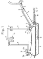
- FIG. 1 shows a fuel storing device for an automobile according to the first embodiment of the present invention.
- a tank shell 1 is made of rigid material such as metal or plastic.
- a side of the tank shell 1 has a flange 2 to attach pipes thereto.
- a separator film 3 is made of flexible material.
- the top of the separator film 3 is tightly fitted around a port 1a for discharging evaporated fuel and around the flange 2.
- the other part of the separator film 3 freely moves with the surface of liquid fuel in the tank shell 1 according to the actions of a pressure adjuster 15.
- the bottom of the separator film 3 may be thickened or fixed to the tank shell 1, to improve the durability thereof against friction caused when the automobile accelerates or decelerates.
- the separator film 3 defines a fuel storage part K and a space L in the tank shell 1.
- a filler pipe 4 is used to pour fuel into the storage part K.
- the filler pipe 4 extends up to an external body of the automobile and is covered with a filler cap, which is removed when refueling. In Fig. 1, the filler cap is removed and a refueling nozzle 5 is inserted in the filler pipe 4 for refueling.
- the filler pipe 4 has a nozzle seal 6 to seal a gap between the refueling nozzle 5 and the filler pipe 4.
- An opening of the filler pipe 4 adjacent to the separator film 3 has a check valve 7.
- the check valve 7 prevents fuel in the fuel storage part K from rushing back into the filler pipe 4.
- a conduit 8 connects a part of the filler pipe 4 below the nozzle seal 6 to an upper part of the fuel storage part K.
- a conduit cover 9 acts as a closure preventive unit according to the present invention, and prevents the opening of the conduit 8 from being closed by the separator film 3.
- the port 1a has a rollover valve 10, which is connected to a vapor line 11.
- the vapor line 11 has a reed valve 12 and is connected to a canister 13. If the car rolls over, the rollover valve 10 prevents fuel in the tank shall 1 from leaking outside. When the car is in a normal posture, the rollover valve 10 passes evaporated fuel from the tank shell 1 to the canister 13.
- the reed valve 12 blocks a flow from the canister 13 toward the fuel storage part K and allows a flow from the part K toward the canister 13. Accordingly, evaporated fuel produced in the part K is adsorbed by the canister 13.
- the canister 13 is connected to an intake duct (not shown) of an engine of the automobile through a purge line 14. Fuel released from the canister 13 is burned in the engine together with a mixture of intake air introduced through an air cleaner and fuel injected from a fuel injector.
- the pressure adjuster 15 adjusts a pressure in the space L according to a change in the surface of the liquid fuel in the fuel storage part K.
- the pressure adjuster 15 has a first valve 15a and a second valve 15b.
- the first valve 15a opens to let the atmospheric pressure press the separator film 3 so that the separator film 3 may be in close contact with the surface of liquid fuel.
- the second valve 15b opens to release the pressure of the space L into the canister 13 through a line 16, thereby preventing an excessive pressure on the fuel storage part K. Except during refueling, the second valve 15b is closed to close the space L and pressurize the part K to promote discharging evaporated fuel from the part K into the canister 13.
- a pipe 17 has a filter 18 arranged at the bottom of the fuel storage part K.
- the pipe 17 is connected to a fuel pump 19 that sends fuel to the fuel injector of the engine.
- a return pipe 20 has an end connected to the pipe 17 in front of the fuel injector and another end connected to the part K, to return excessive fuel from the fuel injector to the part K.
- FIG. 2 shows the details of the refueling nozzle 5.
- the refueling nozzle 5 has a nozzle pipe 50.
- the nozzle pipe 50 is tapered toward a front end thereof so that it is sealed by the nozzle seal 6 when the same is inserted into the filler pipe 4.
- a first valve mechanism 51 is arranged upstream of a bend of the nozzle pipe 50.
- the first valve mechanism 51 has a seat 52 having a center path, and a plug 53.
- a spring 54 is attached to the nozzle pipe 50 and always pushes the plug 53 to the seat 52.
- the plug 53 has a rod 55, which extends outside the nozzle pipe 50.
- a lever 56 is rotatably attached to a shaft 58, which is attached to a rod 57b of a diaphragm 57.
- the rod 57b is fixed to a movable member 57a.
- a grip 59 has a spring 59a to always push the lever 56 downwardly.
- the nozzle pipe 50 of the refueling nozzle 5 When refueling, the nozzle pipe 50 of the refueling nozzle 5 is inserted into the filler pipe 4 until it is sufficiently sealed with the nozzle seal 6.
- the lever 56 is turned upwardly so that a free end 56a thereof rises above a stopper 59b of the grip 59. At this time, there is no negative pressure in the chamber 57c so that the shaft 58 is at a right end position.
- the second valve mechanism 60 has a seat 61, a plug 62, and a weak spring 63 for pushing the plug 62 to the seat 61.
- the spring 63 is fitted to the nozzle pipe 50.
- the seat 61 has a path 61a whose downstream side is widened.
- An annular air path 61b is formed inside the seat 61.
- the air path 61b communicates with the path 61a through oblique paths 61c, with the chamber 57c through an air path 61d, and with an area A between the nozzle pipe 50 and the filler pipe 4 through a pressure guide 61e.
- the fuel reaching the upstream side of the second valve mechanism 60 enters the path 61a of the seat 61.
- the fuel pushes the spring 63 and reaches the downstream side of the second valve mechanism 60.
- the fuel goes out of the refueling nozzle 5, passes through the filler pipe 4, and enters the fuel storage part K.
- the fuel from the refueling nozzle 5 brings air into the fuel storage part K.
- the conduit 8 is open to the fuel storage part K, and therefore, the air brought into the part K escapes through the conduit 8 to the outside of the nozzle pipe 50. As a result, no negative pressure occurs in the area A.
- the chamber 57c of the diaphragm 57 has no negative pressure, and the shaft 58 is kept at the right end position to stop the free end 56a of the lever 56 on the stopper 59b. Consequently, the first valve mechanism 51 is kept open to pass fuel.
- the spring 54 pushes the plug 53 of the first valve mechanism 51 toward the seat 52, to close the path 52a and stop fuel from entering. Then, the plug 62 of the second valve mechanism 60 closes the path 61a.
- the check valve 7 prevents the fuel in the fuel storage part K from blowing back into the filler pipe 4.
- evaporated fuel passes through the vapor line 11 and is adsorbed by the canister 13.
- the pressure of the space L increases to open the second valve 15b of the pressure adjuster 15, thereby maintaining the pressure of the space L at a proper level.
- Figure 3 shows a fuel storing device for an automobile according to the second embodiment of the present invention.
- the second embodiment curves the front end of the conduit 8, instead of employing the conduit cover 9 of the first embodiment.
- the other parts of the second embodiment are the same as those of the first embodiment.
- An opening of the curved end of the conduit 8 faces the flange 2. Even if the amount of fuel in the fuel storage part K is too little to greatly deform the separator film 3, the separator film 3 will never block the opening of the curved end of the conduit 8.
- the second embodiment provides the same effect, as the first embodiment, of automatically stopping refueling only after the fuel container 1 is fully filled with fuel.
- the second embodiment is simpler and cheaper because it provides the effect of the present invention by only bending the front end of the conduit 8.
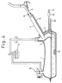
- FIG. 4 shows a fuel storing device for an automobile according to the third embodiment of the present invention.
- the third embodiment extends the filler pipe 4 over the conduit 8 in the vicinity of the fuel storage part K, instead of employing the conduit cover 9 of the first embodiment.
- the other parts of the third embodiment are the same as those of the first embodiment.
- the third embodiment provides the same effect as the first and second embodiments of automatically stopping refueling only after the fuel storage container 1 is fully filled with fuel.
- the third embodiment is cheaper because it needs no additional parts or a bending process.
- FIG. 5 shows a fuel storing device for an automobile according to the fourth embodiment of the present invention.
- the fourth embodiment provides the separation film 3 with a thick part 3a that is relatively rigid, instead of employing the conduit cover 9 of the first embodiment.
- the other parts of the fourth embodiment are the same as those of the first embodiment. Even if the amount of fuel in the fuel storage part K is too little to greatly deform the separation film 3, the separation film 3 will never block the opening of the front end of the conduit 8 because the thick part 3a is rigid and does not deform.
- the fourth embodiment provides the same effect, as the first to third embodiments, of automatically stopping refueling only after the fuel storage container is fully filled with fuel.
- the fourth embodiment is cheaper because it needs no additional parts or a bending process.
- Figure 6 shows a fuel storing device for an automobile according to the fifth embodiment of the present invention.
- the fifth embodiment shapes the separator film 3 into a bag 3a and encloses the fuel storage part K with the bag 3a.
- the other parts of the fifth embodiment are the same as those of the first embodiment.
- the separation bag 3a of the fifth embodiment is applicable to any one of the second to fourth embodiments.
- Figure 7 shows a fuel storing device for an automobile according to the sixth embodiment of the present invention.
- the sixth embodiment shapes the separator film 3 into a bag 3b and encloses the space L with the bag 3b.
- the other parts of the sixth embodiment are the same as those of the first embodiment.
- the separation bag 3b of the sixth embodiment is applicable to any one of the second to fourth embodiments.
- the present invention provides a fuel storing device for an automobile, having a separator film that separates the inside of a fuel storage container of the fuel storing device into a fuel storage part and a space above the fuel storage part, which can prevent an automatic stopper of a refueling nozzle from erroneous operation to stop refueling before the fuel storage container is fully filled with fuel.
- a fuel tank for an automobile has a separator film to separate the inside of a fuel storage container of the fuel storing device into a fuel storage part and a space.
- the separator film is movable with a surface of liquid fuel in the fuel storage part.
- a filler pipe is connected to the fuel storage part.
- the filler pipe has a nozzle seal that seals a gap with respect to a refueling nozzle inserted into the filler pipe.
- a conduit communicates a part of the filler pipe adjacent to the nozzle seal with an upper part of the fuel storage part.
- a closure preventing means prevents the separator film from closing an opening of the conduit at the upper part of the fuel storage part.
- the closure preventing means prevents a negative pressure from being produced around the refueling nozzle before the fuel storage container is fully filled with fuel.
- the closure preventing means lets the automatic stopper stop the supply of fuel in response to a negative pressure only after the fuel storage container is fully filled with fuel.
Landscapes
- Engineering & Computer Science (AREA)
- Life Sciences & Earth Sciences (AREA)
- Sustainable Development (AREA)
- Sustainable Energy (AREA)
- Chemical & Material Sciences (AREA)
- Combustion & Propulsion (AREA)
- Transportation (AREA)
- Mechanical Engineering (AREA)
- Cooling, Air Intake And Gas Exhaust, And Fuel Tank Arrangements In Propulsion Units (AREA)
- Supplying Secondary Fuel Or The Like To Fuel, Air Or Fuel-Air Mixtures (AREA)
Applications Claiming Priority (3)
| Application Number | Priority Date | Filing Date | Title |
|---|---|---|---|
| JP04332396A JP3362594B2 (ja) | 1996-02-29 | 1996-02-29 | 自動車用燃料貯留装置 |
| JP4332396 | 1996-02-29 | ||
| JP43323/96 | 1996-02-29 |
Publications (3)
| Publication Number | Publication Date |
|---|---|
| EP0792767A2 true EP0792767A2 (fr) | 1997-09-03 |
| EP0792767A3 EP0792767A3 (fr) | 1998-04-15 |
| EP0792767B1 EP0792767B1 (fr) | 2000-01-05 |
Family
ID=12660615
Family Applications (1)
| Application Number | Title | Priority Date | Filing Date |
|---|---|---|---|
| EP19970103383 Expired - Lifetime EP0792767B1 (fr) | 1996-02-29 | 1997-02-28 | Réservoir de carburant pour automobile |
Country Status (4)
| Country | Link |
|---|---|
| US (1) | US5746186A (fr) |
| EP (1) | EP0792767B1 (fr) |
| JP (1) | JP3362594B2 (fr) |
| DE (1) | DE69701048T2 (fr) |
Cited By (7)
| Publication number | Priority date | Publication date | Assignee | Title |
|---|---|---|---|---|
| DE19805220A1 (de) * | 1998-02-10 | 1999-08-12 | Mannesmann Sachs Ag | Kraftstoffversorgungssystem |
| WO2000032431A1 (fr) * | 1998-11-28 | 2000-06-08 | Bayerische Motoren Werke Aktiengesellschaft | Ensemble reservoir de carburant pour vehicules a moteur |
| EP0976602A3 (fr) * | 1998-07-27 | 2001-01-24 | Kautex Textron GmbH & Co. KG. | Réservoir de carburant |
| EP1028017A3 (fr) * | 1999-02-10 | 2002-09-18 | Siemens Aktiengesellschaft | Réservoir de carburant |
| WO2009000362A1 (fr) * | 2007-06-22 | 2008-12-31 | Kautex Textron Gmbh & Co. Kg | Réservoir de carburant |
| WO2012055474A1 (fr) * | 2010-10-28 | 2012-05-03 | Kautex Textron Gmbh & Co.Kg | Réservoir de carburant pour véhicules à moteur |
| US9592729B2 (en) | 2010-11-17 | 2017-03-14 | Aisan Kogyo Kabushiki Kaisha | Fuel tank |
Families Citing this family (19)
| Publication number | Priority date | Publication date | Assignee | Title |
|---|---|---|---|---|
| US5925817A (en) * | 1996-12-26 | 1999-07-20 | Toyota Jidosha Kabushiki Kaisha | Device for diagnosing malfunction in a fuel tank |
| JP3438575B2 (ja) * | 1997-04-30 | 2003-08-18 | トヨタ自動車株式会社 | 燃料貯留装置 |
| JP3392746B2 (ja) | 1998-03-05 | 2003-03-31 | トヨタ自動車株式会社 | 燃料タンク |
| JP3381248B2 (ja) * | 1998-03-23 | 2003-02-24 | トヨタ自動車株式会社 | 燃料タンク |
| US6240908B1 (en) * | 1998-06-22 | 2001-06-05 | Toyota Jidosha Kabushiki Kaisha | Fuel storage device diagnostic apparatus |
| US6453885B1 (en) * | 1999-12-18 | 2002-09-24 | Delphi Technologies, Inc. | Vapor removal fuel containment fuel tank |
| US7429322B2 (en) * | 2003-11-20 | 2008-09-30 | Honda Motor Co., Ltd. | Fuel tank with filters |
| KR100924188B1 (ko) | 2007-10-23 | 2009-10-29 | 지엠대우오토앤테크놀로지주식회사 | 연료탱크 |
| JP2010019151A (ja) * | 2008-07-10 | 2010-01-28 | Nifco Inc | 燃料用フィルタ |
| JP2011161974A (ja) * | 2010-02-05 | 2011-08-25 | Toyota Motor Corp | 燃料タンク、並びに同燃料タンクを具備する蒸発燃料処理装置 |
| US8372278B1 (en) * | 2012-03-21 | 2013-02-12 | GM Global Technology Operations LLC | Liquid fuel strainer assembly |
| US9488136B2 (en) * | 2013-09-24 | 2016-11-08 | Ford Global Technologies, Llc | Fuel oxidation reduction for hybrid vehicles |
| JP2017001571A (ja) * | 2015-06-12 | 2017-01-05 | トヨタ自動車株式会社 | 燃料タンク構造 |
| JP6311656B2 (ja) * | 2015-06-16 | 2018-04-18 | トヨタ自動車株式会社 | 燃料タンク構造 |
| DE102016207741A1 (de) * | 2016-05-04 | 2017-11-09 | Bayerische Motoren Werke Aktiengesellschaft | Tanksystem eines Kraftfahrzeugs mit einem Volumenveränderungselement |
| CN108397312A (zh) * | 2018-03-31 | 2018-08-14 | 重庆长安汽车股份有限公司 | 一种燃油系统蒸汽回收方法、系统及车辆 |
| CN109835187B (zh) * | 2018-12-29 | 2022-04-19 | 大乘汽车有限公司 | 一种车辆自动熄火系统及其控制方法 |
| US11754012B1 (en) * | 2022-06-03 | 2023-09-12 | Ford Global Technologies, Llc | Methods and systems for a pressureless fuel tank |
| US12163481B2 (en) * | 2023-01-27 | 2024-12-10 | Ford Global Technologies, Llc | Vehicle and corresponding fuel system |
Family Cites Families (16)
| Publication number | Priority date | Publication date | Assignee | Title |
|---|---|---|---|---|
| DE1008134B (de) * | 1956-01-28 | 1957-05-09 | Werner Hasler | Explosionssicherer Behaelter fuer fluessige Treibstoffe |
| US3617034A (en) * | 1970-02-25 | 1971-11-02 | Union Oil Co | Internal combustion engine fuel system minimizing evaporative fuel losses |
| US3977379A (en) * | 1971-01-05 | 1976-08-31 | Joseph Weissenbach | Contained volatile liquids vapor retention system |
| US3693825A (en) * | 1971-06-28 | 1972-09-26 | Gen Motors Corp | Fuel tank having bellows for control of fuel evaporation |
| US3701540A (en) * | 1971-12-10 | 1972-10-31 | William L Pringle And Associat | Fuel tank assembly |
| US3949720A (en) * | 1974-02-25 | 1976-04-13 | Zipprich Charles F | Fuel container systems |
| US3968896A (en) * | 1975-06-20 | 1976-07-13 | General Motors Corporation | Fuel tank |
| US4633698A (en) * | 1983-12-21 | 1987-01-06 | Hans Oetiker | Method for preforming a substantially flat blank of an open clamp |
| JPS60157427A (ja) * | 1984-01-25 | 1985-08-17 | Hitachi Ltd | 自動搬送装置のコンテナの管理方法 |
| JPS60158922A (ja) * | 1984-01-30 | 1985-08-20 | Hashimoto Forming Co Ltd | モ−ルデイング類の曲げ加工装置 |
| JPS6416426A (en) * | 1987-07-10 | 1989-01-19 | Nippon Denso Co | Storage device for liquid fuel of automobile |
| US4852765A (en) * | 1988-09-12 | 1989-08-01 | Chrysler Motors Corporation | Fuel tank with bladder |
| US5056493A (en) * | 1989-01-24 | 1991-10-15 | Walter Holzer | Environmentally harmonious fuel tank |
| GB9318943D0 (en) * | 1993-09-14 | 1993-10-27 | Dowty Woodville Polymer Ltd | Fuel storage vessels |
| JP3205824B2 (ja) * | 1993-11-09 | 2001-09-04 | 豊田合成株式会社 | 液体燃料貯留装置 |
| US5596971A (en) * | 1994-10-21 | 1997-01-28 | Toyota Jidosha Kabushiki Kaisha | Fuel storing device for motor vehicle |
-
1996
- 1996-02-29 JP JP04332396A patent/JP3362594B2/ja not_active Expired - Fee Related
-
1997
- 1997-02-27 US US08/807,169 patent/US5746186A/en not_active Expired - Lifetime
- 1997-02-28 DE DE69701048T patent/DE69701048T2/de not_active Expired - Lifetime
- 1997-02-28 EP EP19970103383 patent/EP0792767B1/fr not_active Expired - Lifetime
Cited By (8)
| Publication number | Priority date | Publication date | Assignee | Title |
|---|---|---|---|---|
| DE19805220A1 (de) * | 1998-02-10 | 1999-08-12 | Mannesmann Sachs Ag | Kraftstoffversorgungssystem |
| EP0976602A3 (fr) * | 1998-07-27 | 2001-01-24 | Kautex Textron GmbH & Co. KG. | Réservoir de carburant |
| WO2000032431A1 (fr) * | 1998-11-28 | 2000-06-08 | Bayerische Motoren Werke Aktiengesellschaft | Ensemble reservoir de carburant pour vehicules a moteur |
| EP1028017A3 (fr) * | 1999-02-10 | 2002-09-18 | Siemens Aktiengesellschaft | Réservoir de carburant |
| WO2009000362A1 (fr) * | 2007-06-22 | 2008-12-31 | Kautex Textron Gmbh & Co. Kg | Réservoir de carburant |
| US8678226B2 (en) | 2007-06-22 | 2014-03-25 | Kautex Textron Gmbh & Co. Kg | Fuel container |
| WO2012055474A1 (fr) * | 2010-10-28 | 2012-05-03 | Kautex Textron Gmbh & Co.Kg | Réservoir de carburant pour véhicules à moteur |
| US9592729B2 (en) | 2010-11-17 | 2017-03-14 | Aisan Kogyo Kabushiki Kaisha | Fuel tank |
Also Published As
| Publication number | Publication date |
|---|---|
| JP3362594B2 (ja) | 2003-01-07 |
| EP0792767B1 (fr) | 2000-01-05 |
| DE69701048T2 (de) | 2000-06-29 |
| JPH09236059A (ja) | 1997-09-09 |
| EP0792767A3 (fr) | 1998-04-15 |
| DE69701048D1 (de) | 2000-02-10 |
| US5746186A (en) | 1998-05-05 |
Similar Documents
| Publication | Publication Date | Title |
|---|---|---|
| US5746186A (en) | Fuel storing device for an automobile | |
| US5868120A (en) | Fuel vapor management system for motor vehicles | |
| TWI246474B (en) | Method and system for controlling liquid fuel and vapor flow during refueling of a motor vehicle fuel tank | |
| US6029635A (en) | Fuel vapor emission preventing system | |
| CN101378930B (zh) | 用于机动车辆的燃料箱 | |
| JPH01172023A (ja) | 自動車の燃料タンクへの給油時に燃料蒸気を阻止する装置 | |
| JPH04224420A (ja) | キヤツプレス車両燃料補給システム | |
| US4798306A (en) | Fuel tank venting | |
| JPH09203359A (ja) | 自動車用燃料貯留装置 | |
| US7258130B2 (en) | Integrated jet fluid level shutoff sensor and fuel tank vent for vehicles | |
| US6006799A (en) | Motor vehicle tank | |
| JPH08282310A (ja) | 蒸発燃料排出防止装置 | |
| JPH11147422A (ja) | 燃料タンク用燃料給入管 | |
| JP3739434B2 (ja) | 燃料蒸気排出防止装置 | |
| BG64548B1 (bg) | Предпазен вентил | |
| EP1433646A1 (fr) | Dispositif pour traitement des vapeurs de carburant | |
| WO2007088023A1 (fr) | Réservoir de carburant pour véhicule à moteur | |
| JP2005104394A (ja) | 蒸発燃料排出抑制装置 | |
| JP2001165003A (ja) | 燃料タンク | |
| JP2000018112A (ja) | 蒸発燃料制御装置 | |
| JP2562201Y2 (ja) | 燃料タンクの給油部構造 | |
| JP3146753B2 (ja) | 自動車用燃料タンク | |
| JPH0546502Y2 (fr) | ||
| JPH08197968A (ja) | 車両用燃料貯留装置 | |
| JP3788264B2 (ja) | 給油システム |
Legal Events
| Date | Code | Title | Description |
|---|---|---|---|
| PUAI | Public reference made under article 153(3) epc to a published international application that has entered the european phase |
Free format text: ORIGINAL CODE: 0009012 |
|
| 17P | Request for examination filed |
Effective date: 19970228 |
|
| AK | Designated contracting states |
Kind code of ref document: A2 Designated state(s): DE FR GB |
|
| PUAL | Search report despatched |
Free format text: ORIGINAL CODE: 0009013 |
|
| AK | Designated contracting states |
Kind code of ref document: A3 Designated state(s): DE FR GB |
|
| 17Q | First examination report despatched |
Effective date: 19980610 |
|
| GRAG | Despatch of communication of intention to grant |
Free format text: ORIGINAL CODE: EPIDOS AGRA |
|
| GRAG | Despatch of communication of intention to grant |
Free format text: ORIGINAL CODE: EPIDOS AGRA |
|
| GRAH | Despatch of communication of intention to grant a patent |
Free format text: ORIGINAL CODE: EPIDOS IGRA |
|
| GRAH | Despatch of communication of intention to grant a patent |
Free format text: ORIGINAL CODE: EPIDOS IGRA |
|
| GRAA | (expected) grant |
Free format text: ORIGINAL CODE: 0009210 |
|
| AK | Designated contracting states |
Kind code of ref document: B1 Designated state(s): DE FR GB |
|
| REF | Corresponds to: |
Ref document number: 69701048 Country of ref document: DE Date of ref document: 20000210 |
|
| ET | Fr: translation filed | ||
| PLBE | No opposition filed within time limit |
Free format text: ORIGINAL CODE: 0009261 |
|
| STAA | Information on the status of an ep patent application or granted ep patent |
Free format text: STATUS: NO OPPOSITION FILED WITHIN TIME LIMIT |
|
| 26N | No opposition filed | ||
| REG | Reference to a national code |
Ref country code: GB Ref legal event code: IF02 |
|
| REG | Reference to a national code |
Ref country code: GB Ref legal event code: 746 Effective date: 20050707 |
|
| REG | Reference to a national code |
Ref country code: FR Ref legal event code: D6 |
|
| PGFP | Annual fee paid to national office [announced via postgrant information from national office to epo] |
Ref country code: FR Payment date: 20110218 Year of fee payment: 15 Ref country code: DE Payment date: 20110223 Year of fee payment: 15 |
|
| PGFP | Annual fee paid to national office [announced via postgrant information from national office to epo] |
Ref country code: GB Payment date: 20110223 Year of fee payment: 15 |
|
| GBPC | Gb: european patent ceased through non-payment of renewal fee |
Effective date: 20120228 |
|
| REG | Reference to a national code |
Ref country code: FR Ref legal event code: ST Effective date: 20121031 |
|
| REG | Reference to a national code |
Ref country code: DE Ref legal event code: R119 Ref document number: 69701048 Country of ref document: DE Effective date: 20120901 |
|
| PG25 | Lapsed in a contracting state [announced via postgrant information from national office to epo] |
Ref country code: FR Free format text: LAPSE BECAUSE OF NON-PAYMENT OF DUE FEES Effective date: 20120229 Ref country code: GB Free format text: LAPSE BECAUSE OF NON-PAYMENT OF DUE FEES Effective date: 20120228 |
|
| PG25 | Lapsed in a contracting state [announced via postgrant information from national office to epo] |
Ref country code: DE Free format text: LAPSE BECAUSE OF NON-PAYMENT OF DUE FEES Effective date: 20120901 |