EP0793056B1 - Lichtschiene und Deckenprofil - Google Patents
Lichtschiene und Deckenprofil Download PDFInfo
- Publication number
- EP0793056B1 EP0793056B1 EP97200581A EP97200581A EP0793056B1 EP 0793056 B1 EP0793056 B1 EP 0793056B1 EP 97200581 A EP97200581 A EP 97200581A EP 97200581 A EP97200581 A EP 97200581A EP 0793056 B1 EP0793056 B1 EP 0793056B1
- Authority
- EP
- European Patent Office
- Prior art keywords
- rail
- support element
- lighting
- conducting
- shaped
- Prior art date
- Legal status (The legal status is an assumption and is not a legal conclusion. Google has not performed a legal analysis and makes no representation as to the accuracy of the status listed.)
- Expired - Lifetime
Links
- 239000000725 suspension Substances 0.000 claims description 28
- 238000010422 painting Methods 0.000 claims description 4
- 238000005192 partition Methods 0.000 description 2
- 230000037431 insertion Effects 0.000 description 1
- 238000003780 insertion Methods 0.000 description 1
Images
Classifications
-
- H—ELECTRICITY
- H01—ELECTRIC ELEMENTS
- H01R—ELECTRICALLY-CONDUCTIVE CONNECTIONS; STRUCTURAL ASSOCIATIONS OF A PLURALITY OF MUTUALLY-INSULATED ELECTRICAL CONNECTING ELEMENTS; COUPLING DEVICES; CURRENT COLLECTORS
- H01R25/00—Coupling parts adapted for simultaneous co-operation with two or more identical counterparts, e.g. for distributing energy to two or more circuits
- H01R25/14—Rails or bus-bars constructed so that the counterparts can be connected thereto at any point along their length
-
- A—HUMAN NECESSITIES
- A47—FURNITURE; DOMESTIC ARTICLES OR APPLIANCES; COFFEE MILLS; SPICE MILLS; SUCTION CLEANERS IN GENERAL
- A47G—HOUSEHOLD OR TABLE EQUIPMENT
- A47G1/00—Mirrors; Picture frames or the like, e.g. provided with heating, lighting or ventilating means
- A47G1/16—Devices for hanging or supporting pictures, mirrors, or the like
- A47G1/1686—Picture rails; Accessories therefor, e.g. hooks or the like, specially adapted for use with picture rails
-
- F—MECHANICAL ENGINEERING; LIGHTING; HEATING; WEAPONS; BLASTING
- F21—LIGHTING
- F21V—FUNCTIONAL FEATURES OR DETAILS OF LIGHTING DEVICES OR SYSTEMS THEREOF; STRUCTURAL COMBINATIONS OF LIGHTING DEVICES WITH OTHER ARTICLES, NOT OTHERWISE PROVIDED FOR
- F21V21/00—Supporting, suspending, or attaching arrangements for lighting devices; Hand grips
- F21V21/34—Supporting elements displaceable along a guiding element
- F21V21/35—Supporting elements displaceable along a guiding element with direct electrical contact between the supporting element and electric conductors running along the guiding element
Definitions
- the invention relates to a lighting rail for at least one lighting device.
- the lighting devices are clamped to or in the rail in such a way that the contact portion of the lighting device is pressed against a conducting strip in the rail.
- the lighting device usually has an elongated arm of a considerably length to enable the lamp to light the painting, work of art or other object to the lighted from a direction which is advantageous for exhibition purposes.
- the contact portion of the lighting device must be received and supported in a recess in the lighting rail, and there make contact with the conducting strip.
- the current is then led away through the lighting rail itself, wherein a separate live conducting rail is used, which fits into a support element of the rail. After the support element has been mounted against a wall or a ceiling, for instance by means of screws, the live conducting rail is mounted in the support element.
- the live conducting rail after it has been fitted, cannot or only with great difficulty be removed from the support element, which is disadvantageous, for instance when it is desirable for the lighting rail to be moved.
- the conducting rail can simply be slid into the support element, wherein the protuberance on the one part is received in the recess of the other part, since the leg of the support element and/or the conducting rail bends out somewhat upon insertion. Since the recesses and the protuberances themselves are symmetrical, the conducting rail can also be easily removed from the support element.
- the conducting rail is symmetrical, and consequently the position of the conducting rail upon snapping it in is always correct, and both protuberances ensure a good attachment.
- a dome-shaped cross-section ensures easy snapping in and removal.
- the protuberance or the recess is provided at a distance from the outer end of the leg of the U of the conducting rail which is equal to or smaller than the distance between the corresponding recess or protuberance of the support element and the inside surface of the bottom of the U of the support element so as to enable a reverse mounting of the conducting rail in the support element, the protuberance or the recess preferably being provided halfway the length of the legs of the conducting rail.
- the bottom of the U-shaped conducting rail can, upon reversed placement, come to be situated in one plane with the outer ends of the legs of the support element, which is visually attractive.
- the lighting rail comprises a suspension rail according to claim 4.
- the support element is provided with support means for wall or ceiling plates, said support means being integral with the support element and projecting outwardly from both legs of the support element, so that the lighting device also serves as support of wall or ceiling plates and is at least in part received in the wall or the ceiling. At that location, there is consequently no need for a separate profile for the wall or ceiling plates.
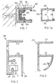
- FIG. 1 shows a preferred embodiment of a lighting rail 201 according to the invention, shown in cross section.
- the lighting rail 201 consists of a substantially U-shaped support element 203 which can be screwed against the wall 202 by means of screws through holes in the bottom of the U.
- a live conducting rail is provided, consisting of the actual conducting rail 204, an insulating strip 205 and a conducting strip 206.
- the insulating strip 205 is kept in place by inwardly directed protuberances on the legs of the rail 204, and the insulating strip 205 itself has protuberances on its outer ends to hold the conducting strip 206.
- Figure 1a shows that the rail 204, at the outer ends of the legs of the U, has inwardly directed lips 210, which are intended to hold the attaching portion (not shown) of a lighting device, the outer end of which is provided with a contact portion for making electrical contact with the conducting strip 206, which contact portion has a width that fits between the legs of the U-shaped conducting strip 206.
- the rail 204 is provided on the outside of the legs of the U with outwardly directed protuberances 212 which can cooperate with corresponding recesses 213 in the support element 203.
- the protuberances 212 and the recesses 213 are preferably dome-shaped in cross-section.
- a "snap" system is provided which is easy to use and wherein the rail 204 can first be provided with the insulating strip 205 and the conducting strip 206 and can subsequently be easily slid and snapped into a support element, which is attached to a wall or a ceiling.
- the rail 204 can also be easily removed from the support element 203, which can be advantageous when, at a certain moment, there is no need for a lighting device.
- the distance L1 between the protuberances 212 and the outer ends of the legs of the rail 204 is equal to or smaller than the distance L2 between the inside surface of the base of the support element and the recess 213, it is possible to close off the lighting rail by arranging the live conducting rail 204 in the support element 203 in a reversed manner, by which the lighting rail is closed off. This gives the lighting rail which is not in use a closed and inconspicuous appearance.
- the protuberances 212 and the recesses 213 are preferably provided substantially halfway the legs of the U, so that both in the position of use and in the closed position the rail 204 comes to be situated in one plane with the outer ends of the legs of the support element.
- the lighting rail according to figure 1 can also comprise a suspension rail for suspending prints, paintings and other objects to be exposed to view, so that it is not necessary to use two separate rails.
- Figures 2 and 3 show the support element of the lighting rail which is provided at its bottom with a suspension rail.
- Figure 2 shows the lighting and suspension rail 220 of which the support element is provided with recesses 225 for a rail 204 as shown in figure 1a.
- the back wall of the support element is extended downwardly and provided with a forwardly projecting portion 221 with an upwardly projecting lip 222, over which a suspension block 10 for a suspension wire 11 can be placed.
- a tongue 224 is also provided, over which a cable can be placed.
- FIG. 3 shows a lighting and suspension rail 230, wherein the support element is provided with recesses 231 for a rail 204, wherein a suspension element can be placed in the lower half of the lighting and suspension rail, and a cable can be placed on the inwardly projecting tongue 232.
- the suspension rail can also have a different shape.
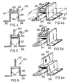
- Figures 4, 5 and 6 show different embodiments of a ceiling profile for a system ceiling, wherein the ceiling profile in all cases consists of an elongated body 301 with an elongated receiving space which is open downwards, and two edges 302 which project outwards on both sides of the elongated body 301 and on which ceiling plates 303 can be supported.
- the elongated body 301 is reversedly U-shaped, and on the inside of the legs of the U recesses 304 are provided, corresponding to protuberances 212 on the outside of a lighting rail 204 as shown in figure 1a.
- Figure 4 shows a ceiling profile 400 wherein the elongated body 301 is provided at its top with upwardly projecting edges 401, each being provided with a lip 402 facing the other.
- a suspension strip is provided which has holes for suspending the ceiling profile. Suspension can be effected by means of wires or bars, which are provided through or in the holes of the suspension strip 403.
- FIG. 5 shows another embodiment of the ceiling profile 500, wherein the elongated body 301 is also provided with upwardly projecting edges 501 which are each provided with a lip 502 facing the other, and wherein in the receiving space as defined a reversed T-shaped suspension block 503 is provided, each T-shaped suspension block in the leg of the T being provided with at least one hole for suspending the ceiling profile.
- the ceiling profile 500 can thus be suspended by means of only a few suspension blocks 503, which suspension blocks are movable in the receiving space of the profile.
- an L-shaped suspension block can also be used, wherein optionally one lip 502 and even the corresponding edge 501 can be cancelled.
- any shape can be selected, which is movable in a corresponding receiving space, such that the ceiling profile can be suspended by the vertical leg.
- the vertical leg can also be provided with for instance a hook for suspension purposes.
- Figure 6 shows a ceiling profile 600 wherein the elongated body 301 is provided at its top with an upwardly extending plate 601, in which two or more holes are provided.
- the ceiling profile 600 can thus be suspended by means of upwardly projecting plate 601. Instead of holes, hooks can also be provided.
- Figures 4a, 5a and 6a show a perspective view of the respective ceiling profiles.
- the respective holes 404, 504 and 602 are herein visible.
- ceiling profiles according to figures 4, 5 and 6 it is possible to install a ceiling system with ceiling plates 303, wherein the ceiling profile is also suitable for receiving a live conducting rail 204 as shown in figure 1a, wherein also an insulating strip 205 and a conducing strip 206 are included.
- the ceiling profile is thereby also suitable for being provided with lighting devices.
- two or more short pieces of ceiling profile arranged in line with each other, can also be used each time.
- a conducting rail 204 can be provided each time. Over the portions of the conducting rail situated between the pieces of ceiling profile a length of the support element 203 according to figure 1 can then be snapped, wherein the bottom of the U-shaped support element is directed downwardly, so that such a length of support element can serve as bearing element for suspension of for instance a partition wall.
- the partition wall and the like can be attached to the support element with screws or by means of wires or bars.
Landscapes
- Engineering & Computer Science (AREA)
- General Engineering & Computer Science (AREA)
- Mirrors, Picture Frames, Photograph Stands, And Related Fastening Devices (AREA)
Claims (6)
- Lichtschiene (201) für zumindest eine Beleuchtungsvorrichtung, welche mit einem Kontaktabschnitt für elektrischen Kontakt mit einem Führungsstreifen (206) der Lichtschiene versehen ist, wobei die Lichtschiene ein im Durchschnitt hauptsächlich U-förmiges Stützelement, eine im Durchschnitt hauptsächlich U-förmige stromführende im Stützelement passende Führungsschiene (204), und Isoliermittel (205) zum Isolieren der Führungsschiene von dem darin angeordneten Führungsstreifen umfaßt, wobei die Führungsschiene und das Stützelement zusammenwirkende Befestigungsmittel umfassen, wobei zumindest ein Schenkel der hauptsächlich U-förmigen stromführenden Führungsschiene an der Außenseite eine Herausragung oder Aussparung (212) umfaßt, und wobei zumindest eine Wand des Stützelementes (203) eine entsprechende Aussparung oder Herausragung (213) umfaßt, um die stromführende Führungsschiene (204) durch Einschnappen abnehmbar in dem Stützelement zu befestigen, dadurch gekennzeichnet, daß die Herausragungen oder Aussparungen (212, 213) selbst hauptsächlich symmetrisch sind und daß beide Schenkel der Führungsschiene (206) und beide Wände des Stützelementes (203) mit einer solchen Herausragung oder Aussparung (212, 213) versehen sind.
- Lichtschiene nach Anspruch 1, wobei die U-förmige Führungsschiene symmetrisch ist, so daß die Herausragungen oder Aussparungen in ihren Schenkeln auf demselben Abstand von der Basis der U-förmigen Führungsschiene gelegen sind.
- Lichtschiene nach Anspruch 1 oder 2, wobei die Herausragungen und Aussparungen (212, 213) im Durchschnitt kuppelförmig sind.
- Lichtschiene nach Anspruch 1, 2 oder 3, wobei die Herausragung oder die Aussparung (212) auf einem Abstand von dem Außenende des Schenkels der U der Führungsschiene (204) vorgesehen ist, welcher Abstand gleich ist an oder kleiner ist als der Abstand zwischen der entsprechenden Aussparung oder Herausragung (213) des Stützelementes (203) und der Innenfläche des Bodens der U des Stützelementes (203), um so eine umgekehrte Aufstellung der Führungsschiene in dem Stützelement zu ermöglichen, wobei die Herausragung oder die Aussparung vorzugsweise auf der Hälfte der Länge der Schenkel der Führungsschiene vorgesehen ist.
- Lichtschiene nach einem der vorhergehenden Ansprüche, wobei die Lichtschiene (201) eine Aufhängeschiene (220) zum Aufhängen von Bildern, Gemälden und anderen zur Besichtigung aufzustellenden Gegenständen umfaßt, welche Aufhängeschiene geeignet ist, um Aufhängeelemente für die aufzuhängenden Gegenstände aufzunehmen und verstellbar zu halten, und welche Aufhängeschiene ein Ganzes mit der Lichtschiene bildet.
- Lichtschiene nach einem der Ansprüche 1-4, wobei das Stützelement mit Stützmitteln für Wand- oder Deckenplatten versehen ist, wobei die Stützmittel mit dem Stützelement ein Ganzes bilden und ab beiden Schenkeln des Stützelementes auswärts herausragen.
Applications Claiming Priority (2)
| Application Number | Priority Date | Filing Date | Title |
|---|---|---|---|
| US608753 | 1996-02-29 | ||
| US08/608,753 US6325645B1 (en) | 1996-02-29 | 1996-02-29 | Lighting rail for lighting objects to be exposed to view |
Publications (3)
| Publication Number | Publication Date |
|---|---|
| EP0793056A2 EP0793056A2 (de) | 1997-09-03 |
| EP0793056A3 EP0793056A3 (de) | 1997-11-26 |
| EP0793056B1 true EP0793056B1 (de) | 2003-08-20 |
Family
ID=24437832
Family Applications (1)
| Application Number | Title | Priority Date | Filing Date |
|---|---|---|---|
| EP97200581A Expired - Lifetime EP0793056B1 (de) | 1996-02-29 | 1997-02-28 | Lichtschiene und Deckenprofil |
Country Status (3)
| Country | Link |
|---|---|
| US (1) | US6325645B1 (de) |
| EP (1) | EP0793056B1 (de) |
| DE (1) | DE69724174D1 (de) |
Families Citing this family (28)
| Publication number | Priority date | Publication date | Assignee | Title |
|---|---|---|---|---|
| US6409524B1 (en) * | 2001-07-30 | 2002-06-25 | Jack V. Miller | Side-mounted tracklight system |
| US7188805B2 (en) * | 2004-03-27 | 2007-03-13 | The Boeing Company | Continuous power bus for seat power |
| US20080253112A1 (en) * | 2007-04-10 | 2008-10-16 | Nash Alan C | Hand rail system railing connector |
| US7762821B2 (en) | 2006-10-17 | 2010-07-27 | Worthington Armstrong Venture | Electrified ceiling framework |
| ITMC20070044A1 (it) * | 2007-02-28 | 2008-09-01 | Compagnucci Holding Spa | Mobile pensile per cucine componibili. |
| US7744386B1 (en) * | 2009-11-02 | 2010-06-29 | Lighting Services Inc. | High amperage busway system |
| AT509686B1 (de) * | 2010-04-09 | 2011-11-15 | Hierzer Andreas | Halterungsprofil mit zumindest einer beleuchtungseinheit |
| JP5842132B2 (ja) * | 2011-09-21 | 2016-01-13 | パナソニックIpマネジメント株式会社 | 照明器具 |
| CN103066459A (zh) * | 2011-10-20 | 2013-04-24 | 鸿富锦精密工业(深圳)有限公司 | 旋转式插座 |
| EP2977518B1 (de) * | 2014-07-24 | 2016-11-16 | Normalu | Leuchtleiste für Blindwand aus gespanntem Stoff, und eine solche Leiste umfassende Blindwand |
| CN108123337B (zh) | 2016-11-28 | 2021-06-22 | 泰连公司 | 用于通信系统的电力连接器组件 |
| US12233756B2 (en) | 2018-05-04 | 2025-02-25 | Lear Corporation | Track system with a support member |
| US11040638B2 (en) | 2018-05-04 | 2021-06-22 | Lear Corporation | Track assembly |
| US10673189B2 (en) * | 2018-06-06 | 2020-06-02 | Te Connectivity Corporation | Power connector assembly for a communication system |
| US10939576B2 (en) | 2018-11-28 | 2021-03-02 | Te Connectivity Corporation | Power connector assembly for a communication system |
| US11117538B2 (en) | 2018-12-17 | 2021-09-14 | Lear Corporation | Electrical assembly |
| US11613220B2 (en) | 2018-12-17 | 2023-03-28 | Lear Corporation | Electrical assembly |
| US10950977B2 (en) * | 2018-12-18 | 2021-03-16 | Lear Corporation | Track assembly for a vehicle component |
| US11975665B2 (en) | 2019-02-20 | 2024-05-07 | Lear Corporation | Electrical assembly |
| US11807142B2 (en) | 2019-03-06 | 2023-11-07 | Lear Corporation | Electrical track assembly |
| US11299075B2 (en) | 2019-03-06 | 2022-04-12 | Lear Corporation | Electrical assembly |
| US11463083B2 (en) | 2019-10-04 | 2022-10-04 | Lear Corporation | Electrical system |
| US11634101B2 (en) | 2019-10-04 | 2023-04-25 | Lear Corporation | Removable component system |
| US11323114B2 (en) | 2019-10-04 | 2022-05-03 | Lear Corporation | Electrical system |
| US11906028B2 (en) | 2020-02-21 | 2024-02-20 | Lear Corporation | Track system with a support member |
| DE102021104018B4 (de) | 2020-02-21 | 2023-11-09 | Lear Corporation | Schienensystem mit einem Stützelement, Verfahren zum Betreiben eines Schienensystems |
| US11505141B2 (en) | 2020-10-23 | 2022-11-22 | Lear Corporation | Electrical system with track assembly and support assembly |
| CN112484001B (zh) * | 2020-11-30 | 2026-03-31 | 赛尔富电子有限公司 | 一种嵌入式货架取电系统 |
Family Cites Families (7)
| Publication number | Priority date | Publication date | Assignee | Title |
|---|---|---|---|---|
| DE1764787A1 (de) * | 1968-08-07 | 1971-11-04 | Reininghaus & Co | Vorrichtung zur lagegerechten Aufhaengung von Beleuchtungskoerpern |
| US3639885A (en) * | 1968-11-11 | 1972-02-01 | Matsushita Electric Works Ltd | Distribution device |
| CH482329A (de) * | 1968-12-06 | 1969-11-30 | Oskar Woertz Inh H & O Woertz | Elektrische Installationseinrichtung mit mindestens einer Stromführungsschiene |
| US3737834A (en) * | 1971-09-20 | 1973-06-05 | Us Industries Inc | Adapter for three conductor electrical power distribution track |
| US4414617A (en) * | 1981-10-19 | 1983-11-08 | Bruce Petillo | Track lighting system |
| NL194857C (nl) * | 1993-08-19 | 2003-05-06 | Jsi Art Fix Systems Bv | Ophanginrichting voor het ophangen en verlichten van prenten en dergelijke. |
| NL1000153C1 (nl) * | 1995-04-18 | 1996-10-21 | Stichting Kennis Beheer Nederl | Veerbelaste stroomafnemer voor opneming van een verlichtings- inrichting in geleidingsrail voor electriciteitstoevoer. |
-
1996
- 1996-02-29 US US08/608,753 patent/US6325645B1/en not_active Expired - Fee Related
-
1997
- 1997-02-28 EP EP97200581A patent/EP0793056B1/de not_active Expired - Lifetime
- 1997-02-28 DE DE69724174T patent/DE69724174D1/de not_active Expired - Lifetime
Also Published As
| Publication number | Publication date |
|---|---|
| EP0793056A3 (de) | 1997-11-26 |
| US6325645B1 (en) | 2001-12-04 |
| DE69724174D1 (de) | 2003-09-25 |
| EP0793056A2 (de) | 1997-09-03 |
Similar Documents
| Publication | Publication Date | Title |
|---|---|---|
| EP0793056A2 (de) | Lichtschiene und Deckenprofil | |
| US6527565B1 (en) | Adjustable light display assembly | |
| US6345800B1 (en) | Universal load-bearing hanger bracket and method for hanging a lighting fixture below a grid ceiling system at on-grid or off-grid locations | |
| CA1304212C (en) | Electrical raceway floor track | |
| CA2371685A1 (en) | Surface-mounted decorative trim ceiling fixture | |
| GB2089016A (en) | Integrated lighting systems for suspended ceilings | |
| US4373111A (en) | Service poles | |
| US6217192B1 (en) | Decorative light string support | |
| US4126971A (en) | Fixture hanging assembly | |
| US5613762A (en) | Light assembly | |
| CA1251185A (en) | Light distributing fixture | |
| GB9700475D0 (en) | Picture hanging system | |
| EP0640309B1 (de) | Aufhängevorrichtung zum Aufhängen und Beleuchten von ausgestellten Gegenstände | |
| GB2322407B (en) | Hook/hanger | |
| NL1014218C2 (nl) | Inrichting voor het verschuifbaar ophangen en verlichten van voorwerpen, zoals bijvoorbeeld schilderijen, afbeeldingen, panelen e.d. | |
| JPH10141339A (ja) | 懸架固定システム | |
| GB9809616D0 (en) | Wall hook attachment | |
| US6315428B1 (en) | Light fixture mounting for suspended ceiling | |
| KR200185886Y1 (ko) | 걸이형 조명등 | |
| CN2348248Y (zh) | 水族灯固定装置 | |
| BE1013602A5 (nl) | Draagconstructie voor een verlichtingsinrichting en werkwijze voor de installatie ervan. | |
| US7673430B1 (en) | Recessed wall-wash staggered mounting system | |
| JP4023892B2 (ja) | 展示パネル用展示物支持装置 | |
| KR102790084B1 (ko) | 조명 레일장치 | |
| US4422272A (en) | Cosmetic cover for channelled type grid systems |
Legal Events
| Date | Code | Title | Description |
|---|---|---|---|
| PUAI | Public reference made under article 153(3) epc to a published international application that has entered the european phase |
Free format text: ORIGINAL CODE: 0009012 |
|
| AK | Designated contracting states |
Kind code of ref document: A2 Designated state(s): BE DE DK ES FR GB IT NL |
|
| PUAL | Search report despatched |
Free format text: ORIGINAL CODE: 0009013 |
|
| AK | Designated contracting states |
Kind code of ref document: A3 Designated state(s): BE DE DK ES FR GB IT NL |
|
| 17P | Request for examination filed |
Effective date: 19980520 |
|
| 17Q | First examination report despatched |
Effective date: 20010621 |
|
| GRAH | Despatch of communication of intention to grant a patent |
Free format text: ORIGINAL CODE: EPIDOS IGRA |
|
| GRAS | Grant fee paid |
Free format text: ORIGINAL CODE: EPIDOSNIGR3 |
|
| GRAA | (expected) grant |
Free format text: ORIGINAL CODE: 0009210 |
|
| AK | Designated contracting states |
Designated state(s): BE DE DK ES FR GB IT NL |
|
| PG25 | Lapsed in a contracting state [announced via postgrant information from national office to epo] |
Ref country code: IT Free format text: LAPSE BECAUSE OF FAILURE TO SUBMIT A TRANSLATION OF THE DESCRIPTION OR TO PAY THE FEE WITHIN THE PRESCRIBED TIME-LIMIT;WARNING: LAPSES OF ITALIAN PATENTS WITH EFFECTIVE DATE BEFORE 2007 MAY HAVE OCCURRED AT ANY TIME BEFORE 2007. THE CORRECT EFFECTIVE DATE MAY BE DIFFERENT FROM THE ONE RECORDED. Effective date: 20030820 Ref country code: FR Free format text: LAPSE BECAUSE OF FAILURE TO SUBMIT A TRANSLATION OF THE DESCRIPTION OR TO PAY THE FEE WITHIN THE PRESCRIBED TIME-LIMIT Effective date: 20030820 |
|
| REG | Reference to a national code |
Ref country code: GB Ref legal event code: FG4D |
|
| REF | Corresponds to: |
Ref document number: 69724174 Country of ref document: DE Date of ref document: 20030925 Kind code of ref document: P |
|
| PG25 | Lapsed in a contracting state [announced via postgrant information from national office to epo] |
Ref country code: DK Free format text: LAPSE BECAUSE OF FAILURE TO SUBMIT A TRANSLATION OF THE DESCRIPTION OR TO PAY THE FEE WITHIN THE PRESCRIBED TIME-LIMIT Effective date: 20031120 |
|
| PG25 | Lapsed in a contracting state [announced via postgrant information from national office to epo] |
Ref country code: DE Free format text: LAPSE BECAUSE OF FAILURE TO SUBMIT A TRANSLATION OF THE DESCRIPTION OR TO PAY THE FEE WITHIN THE PRESCRIBED TIME-LIMIT Effective date: 20031121 |
|
| PG25 | Lapsed in a contracting state [announced via postgrant information from national office to epo] |
Ref country code: ES Free format text: LAPSE BECAUSE OF FAILURE TO SUBMIT A TRANSLATION OF THE DESCRIPTION OR TO PAY THE FEE WITHIN THE PRESCRIBED TIME-LIMIT Effective date: 20031201 |
|
| PG25 | Lapsed in a contracting state [announced via postgrant information from national office to epo] |
Ref country code: GB Free format text: LAPSE BECAUSE OF NON-PAYMENT OF DUE FEES Effective date: 20040228 |
|
| PLBE | No opposition filed within time limit |
Free format text: ORIGINAL CODE: 0009261 |
|
| STAA | Information on the status of an ep patent application or granted ep patent |
Free format text: STATUS: NO OPPOSITION FILED WITHIN TIME LIMIT |
|
| 26N | No opposition filed |
Effective date: 20040524 |
|
| EN | Fr: translation not filed | ||
| GBPC | Gb: european patent ceased through non-payment of renewal fee | ||
| PGFP | Annual fee paid to national office [announced via postgrant information from national office to epo] |
Ref country code: BE Payment date: 20070319 Year of fee payment: 11 |
|
| NLS | Nl: assignments of ep-patents |
Owner name: MARINUS BARBARA ARNOLDUS MARIA STAS Effective date: 20070802 |
|
| BECA | Be: change of holder's address |
Owner name: DENNIS JOHANNES WALTERIUS HUBERTUS VAN BOXTELBURG. Effective date: 20070809 |
|
| BECH | Be: change of holder |
Owner name: DENNIS JOHANNES WALTERIUS HUBERTUS VAN BOXTEL Effective date: 20070809 |
|
| NLS | Nl: assignments of ep-patents |
Owner name: DENNIS JOHANNES WALTERIUS HUBERTUS VAN BOXTEL Effective date: 20080122 |
|
| BERE | Be: lapsed |
Owner name: DENNIS JOHANNES WALTERIUS HUBERTUS VAN BOXTEL Effective date: 20080228 |
|
| PG25 | Lapsed in a contracting state [announced via postgrant information from national office to epo] |
Ref country code: BE Free format text: LAPSE BECAUSE OF NON-PAYMENT OF DUE FEES Effective date: 20080228 |
|
| PGFP | Annual fee paid to national office [announced via postgrant information from national office to epo] |
Ref country code: NL Payment date: 20090217 Year of fee payment: 13 |
|
| REG | Reference to a national code |
Ref country code: NL Ref legal event code: V1 Effective date: 20100901 |
|
| PG25 | Lapsed in a contracting state [announced via postgrant information from national office to epo] |
Ref country code: NL Free format text: LAPSE BECAUSE OF NON-PAYMENT OF DUE FEES Effective date: 20100901 |