EP0793063A1 - Installation de chauffage avec échangeur de chaleur - Google Patents
Installation de chauffage avec échangeur de chaleur Download PDFInfo
- Publication number
- EP0793063A1 EP0793063A1 EP97810081A EP97810081A EP0793063A1 EP 0793063 A1 EP0793063 A1 EP 0793063A1 EP 97810081 A EP97810081 A EP 97810081A EP 97810081 A EP97810081 A EP 97810081A EP 0793063 A1 EP0793063 A1 EP 0793063A1
- Authority
- EP
- European Patent Office
- Prior art keywords
- burner
- heat exchanger
- heating system
- fresh air
- gases
- Prior art date
- Legal status (The legal status is an assumption and is not a legal conclusion. Google has not performed a legal analysis and makes no representation as to the accuracy of the status listed.)
- Granted
Links
- 238000010438 heat treatment Methods 0.000 title claims description 12
- 238000009434 installation Methods 0.000 title 1
- 239000002737 fuel gas Substances 0.000 claims description 9
- 238000002485 combustion reaction Methods 0.000 claims description 8
- 239000000567 combustion gas Substances 0.000 claims description 4
- 238000001816 cooling Methods 0.000 claims description 2
- 239000000523 sample Substances 0.000 claims description 2
- 238000007599 discharging Methods 0.000 claims 1
- 239000003546 flue gas Substances 0.000 claims 1
- 238000006386 neutralization reaction Methods 0.000 claims 1
- 239000000126 substance Substances 0.000 claims 1
- 239000007789 gas Substances 0.000 abstract description 13
- 239000003344 environmental pollutant Substances 0.000 description 6
- 231100000719 pollutant Toxicity 0.000 description 6
- 230000015572 biosynthetic process Effects 0.000 description 2
- 238000009833 condensation Methods 0.000 description 2
- 230000005494 condensation Effects 0.000 description 2
- 230000001105 regulatory effect Effects 0.000 description 2
- 239000004071 soot Substances 0.000 description 2
- 235000008282 Sanguisorba officinalis Nutrition 0.000 description 1
- 244000173853 Sanguisorba officinalis Species 0.000 description 1
- 238000009825 accumulation Methods 0.000 description 1
- 238000006243 chemical reaction Methods 0.000 description 1
- 238000004140 cleaning Methods 0.000 description 1
- 238000010276 construction Methods 0.000 description 1
- 238000005260 corrosion Methods 0.000 description 1
- 230000007797 corrosion Effects 0.000 description 1
- 238000005259 measurement Methods 0.000 description 1
- 238000000034 method Methods 0.000 description 1
- 238000011084 recovery Methods 0.000 description 1
Images
Classifications
-
- F—MECHANICAL ENGINEERING; LIGHTING; HEATING; WEAPONS; BLASTING
- F24—HEATING; RANGES; VENTILATING
- F24H—FLUID HEATERS, e.g. WATER OR AIR HEATERS, HAVING HEAT-GENERATING MEANS, e.g. HEAT PUMPS, IN GENERAL
- F24H9/00—Details
- F24H9/0084—Combustion air preheating
-
- F—MECHANICAL ENGINEERING; LIGHTING; HEATING; WEAPONS; BLASTING
- F24—HEATING; RANGES; VENTILATING
- F24H—FLUID HEATERS, e.g. WATER OR AIR HEATERS, HAVING HEAT-GENERATING MEANS, e.g. HEAT PUMPS, IN GENERAL
- F24H8/00—Fluid heaters characterised by means for extracting latent heat from flue gases by means of condensation
-
- Y—GENERAL TAGGING OF NEW TECHNOLOGICAL DEVELOPMENTS; GENERAL TAGGING OF CROSS-SECTIONAL TECHNOLOGIES SPANNING OVER SEVERAL SECTIONS OF THE IPC; TECHNICAL SUBJECTS COVERED BY FORMER USPC CROSS-REFERENCE ART COLLECTIONS [XRACs] AND DIGESTS
- Y02—TECHNOLOGIES OR APPLICATIONS FOR MITIGATION OR ADAPTATION AGAINST CLIMATE CHANGE
- Y02B—CLIMATE CHANGE MITIGATION TECHNOLOGIES RELATED TO BUILDINGS, e.g. HOUSING, HOUSE APPLIANCES OR RELATED END-USER APPLICATIONS
- Y02B30/00—Energy efficient heating, ventilation or air conditioning [HVAC]
Definitions
- the invention relates to a heating system with a boiler heated by a burner and a heat exchanger connected downstream thereof for cooling the combustion gases and for preheating fresh air supplied by the burner.
- the purpose of such a combination is both to clean the exhaust gases emerging in the chimney from a large part of their pollutants, such as fire ash, soot and the like, and to reduce the heat losses. This allows saved heat energy to be saved. Due to the partial condensation of the exhaust gases in the heat exchanger, the pollutants in the condensate are progressively collected in the fuel gas pipes and finally fed to a separator.
- a heating system has become known.
- a plurality of tubes for guiding the fuel gases in the heat exchanger are formed from horizontal straight tube sections and elbows connecting them, while the fresh air is guided in superimposed, horizontal channels.
- This has the disadvantage that the condensate with the pollutants remains in the horizontal pipe sections and bends and can settle.
- the heat exchanger's resistance to accumulation can extinguish the flame, and the heat transfer between the exhaust gas and fresh air is not optimal.
- the invention aims to overcome these disadvantages. It achieves this through the features of patent claim 1.
- the fan which conveys the fuel gases into the heat exchanger and, on the other hand, draws the heated fresh air out of the same, achieves optimal heating of the fresh air flowing around the pipe coil in cross flow, which is further increased by turbulence in the pipe coil.
- the negative pressure generated by the fan in the combustion chamber prevents the flame from extinguishing and keeps it stable.
- the flame can additionally be cooled by an additional line for returning part of the cooled fuel gases to the burner, which leads to a further improvement in the exhaust gas values.
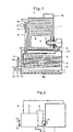
- FIG. 1 of the drawing an embodiment of a heating system according to the invention is shown in section. 2 shows an example of an arrangement of the components of the system.
- Fig. 1 the boiler with the heating coil 2, the burner 3 and the combustion chamber 4 is designated.
- the boiler is followed by a heat exchanger 5.
- the fuel gases are fed into the coil 7 in the exchanger 5, which is continuously bent from top to bottom without deflections.
- Fresh air is introduced from below through line 8 into the exchanger housing. The fresh air exits the tube downwards through a large number of openings 8a, so that a good distribution in the exchanger space is ensured.
- a blower 9 is arranged between the combustion chamber 4 and the exhaust gas line 6 and actively promotes the combustion gases into the coil 7. This creates a negative pressure in the combustion chamber 4 and an excess pressure in the coil 7.
- the fresh air supplied is sucked in at D and fed to the burner E after it flows around the tube coil 7 from bottom to top in a cross flow and is heated in the process.
- the fuel gases are cooled to around 30 - 40 ° C. They condense progressively, the pollutants being bound in the condensate and escaping at 10 together with the cooled fuel gases.
- the continuously draining condensate is separated out in a separator 11 and flows into a collector 12, where it is neutralized in a manner known per se by chemical reaction to such an extent that it can be discharged into the sewer 13 in a pH-neutral manner.
- the exhaust gases reach the chimney at 14.
- the power of the blower motor 15 is regulated by an electronic control 16, which is connected to a pressure probe in the burner chamber 4. It is regulated in such a way that a stable flame is guaranteed with constant combustion conditions. As a result, there is no starting soot and great burner reliability is achieved.
- the delivery pressure creates turbulence in the coil 7. This causes an even higher heat transfer and an even better drainage of the condensate with the pollutants. The heat of condensation is also given off to the fresh air.
- a plurality of coils 7 guided in parallel can also be provided.
- a differently designed heat exchanger device could also be provided with any flow cross-sections and flow guides deviating from spiral shapes, which always enable a continuous condensate drain. Variants also without fan motor.
- a subset of the cooled exhaust gas is returned to the burner flame through a line 17 in order to cool it.
- the temperature thereof can be kept below 1000 ° C, which reduces the formation of NOx.
- the pipe coil has no dead zones in which the condensate could get stuck. It is therefore self-cleaning. Because of the low exhaust gas temperatures, it can be made of plastic, which prevents corrosion. In a system designed according to the invention, the following operating temperatures were measured, for example, at points A - E: A: ⁇ 1000 ° C B: 81 ° C C: 40 ° C D: -9 ° C E: 48 ° C
- the heat recovery for oil or gas burners is approx. 20%
- the heat exchanger does not necessarily have to be located under the boiler. In the exemplary arrangement of the components according to FIG. 2, the heat exchanger is at the same level as the boiler. Other arrangements are possible depending on the structural situation.
Landscapes
- Engineering & Computer Science (AREA)
- Physics & Mathematics (AREA)
- Thermal Sciences (AREA)
- Chemical & Material Sciences (AREA)
- Combustion & Propulsion (AREA)
- Mechanical Engineering (AREA)
- General Engineering & Computer Science (AREA)
- Chimneys And Flues (AREA)
- Heat-Exchange Devices With Radiators And Conduit Assemblies (AREA)
- Sorption Type Refrigeration Machines (AREA)
- Air Supply (AREA)
Applications Claiming Priority (3)
| Application Number | Priority Date | Filing Date | Title |
|---|---|---|---|
| CH531/96 | 1996-03-01 | ||
| CH00531/96A CH690136A5 (de) | 1996-03-01 | 1996-03-01 | Heizanlage mit Wärmetauscher. |
| CH53196 | 1996-03-01 |
Publications (2)
| Publication Number | Publication Date |
|---|---|
| EP0793063A1 true EP0793063A1 (fr) | 1997-09-03 |
| EP0793063B1 EP0793063B1 (fr) | 2000-05-31 |
Family
ID=4189149
Family Applications (1)
| Application Number | Title | Priority Date | Filing Date |
|---|---|---|---|
| EP97810081A Expired - Lifetime EP0793063B1 (fr) | 1996-03-01 | 1997-02-19 | Installation de chauffage avec échangeur de chaleur |
Country Status (4)
| Country | Link |
|---|---|
| EP (1) | EP0793063B1 (fr) |
| AT (1) | ATE193593T1 (fr) |
| CH (1) | CH690136A5 (fr) |
| DE (1) | DE59701792D1 (fr) |
Cited By (5)
| Publication number | Priority date | Publication date | Assignee | Title |
|---|---|---|---|---|
| EP0986721A1 (fr) * | 1996-11-13 | 2000-03-22 | Jan Ericson | Chaudiere et procede servant a optimiser sa combustion |
| DE10025729A1 (de) * | 2000-05-25 | 2002-01-17 | Ryll Heizungs Gmbh | Heizkessel |
| DE102006004506A1 (de) * | 2005-10-27 | 2007-05-10 | Worgas Bruciatori S.R.L. | Brennvorrichtung für Luft-Gas-Gemische |
| EP2295862A3 (fr) * | 2009-08-21 | 2014-06-11 | Vaillant GmbH | Conduit combiné d'air de combustion et de fumées d'un appreil de chauffe |
| EP4443054A1 (fr) | 2023-04-05 | 2024-10-09 | Vaillant GmbH | Installation de chauffage, procédé de fonctionnement d'une installation de chauffage et programme informatique |
Citations (6)
| Publication number | Priority date | Publication date | Assignee | Title |
|---|---|---|---|---|
| GB2043850A (en) * | 1978-12-22 | 1980-10-08 | Nederlandse Gasunie Nv | Boilers for Central Heating Systems |
| EP0106344A2 (fr) * | 1982-10-19 | 1984-04-25 | Hans Dr. Viessmann | Chaudière de chauffage à condensation |
| US4541410A (en) * | 1983-07-20 | 1985-09-17 | Columbia Gas System Service Corporation | Apparatus and method for burning a combustible gas, and a heat exchanger for use in this apparatus |
| US4677939A (en) * | 1985-01-21 | 1987-07-07 | Gaz De France | Heat exchanger and application to a fluid heating apparatus, particularly a domestic hot water accumulator |
| FR2616215A1 (fr) * | 1987-06-05 | 1988-12-09 | Sueddeutsche Kuehler Behr | Echangeur de chaleur circulaire |
| EP0699878A1 (fr) * | 1994-09-01 | 1996-03-06 | EWFE HEIZSYSTEME GmbH | Chauffe-eau à haute rendement pour chauffer et accumuler de l'eau sanitaire et de l'eau de chauffage |
-
1996
- 1996-03-01 CH CH00531/96A patent/CH690136A5/de not_active IP Right Cessation
-
1997
- 1997-02-19 DE DE59701792T patent/DE59701792D1/de not_active Expired - Lifetime
- 1997-02-19 AT AT97810081T patent/ATE193593T1/de not_active IP Right Cessation
- 1997-02-19 EP EP97810081A patent/EP0793063B1/fr not_active Expired - Lifetime
Patent Citations (6)
| Publication number | Priority date | Publication date | Assignee | Title |
|---|---|---|---|---|
| GB2043850A (en) * | 1978-12-22 | 1980-10-08 | Nederlandse Gasunie Nv | Boilers for Central Heating Systems |
| EP0106344A2 (fr) * | 1982-10-19 | 1984-04-25 | Hans Dr. Viessmann | Chaudière de chauffage à condensation |
| US4541410A (en) * | 1983-07-20 | 1985-09-17 | Columbia Gas System Service Corporation | Apparatus and method for burning a combustible gas, and a heat exchanger for use in this apparatus |
| US4677939A (en) * | 1985-01-21 | 1987-07-07 | Gaz De France | Heat exchanger and application to a fluid heating apparatus, particularly a domestic hot water accumulator |
| FR2616215A1 (fr) * | 1987-06-05 | 1988-12-09 | Sueddeutsche Kuehler Behr | Echangeur de chaleur circulaire |
| EP0699878A1 (fr) * | 1994-09-01 | 1996-03-06 | EWFE HEIZSYSTEME GmbH | Chauffe-eau à haute rendement pour chauffer et accumuler de l'eau sanitaire et de l'eau de chauffage |
Cited By (6)
| Publication number | Priority date | Publication date | Assignee | Title |
|---|---|---|---|---|
| EP0986721A1 (fr) * | 1996-11-13 | 2000-03-22 | Jan Ericson | Chaudiere et procede servant a optimiser sa combustion |
| DE10025729A1 (de) * | 2000-05-25 | 2002-01-17 | Ryll Heizungs Gmbh | Heizkessel |
| DE102006004506A1 (de) * | 2005-10-27 | 2007-05-10 | Worgas Bruciatori S.R.L. | Brennvorrichtung für Luft-Gas-Gemische |
| EP2295862A3 (fr) * | 2009-08-21 | 2014-06-11 | Vaillant GmbH | Conduit combiné d'air de combustion et de fumées d'un appreil de chauffe |
| EP4443054A1 (fr) | 2023-04-05 | 2024-10-09 | Vaillant GmbH | Installation de chauffage, procédé de fonctionnement d'une installation de chauffage et programme informatique |
| DE102023108717A1 (de) | 2023-04-05 | 2024-10-10 | Vaillant Gmbh | Heizungsanlage, Verfahren zum Betreiben einer Heizungsanlage und Computerprogramm |
Also Published As
| Publication number | Publication date |
|---|---|
| EP0793063B1 (fr) | 2000-05-31 |
| CH690136A5 (de) | 2000-05-15 |
| DE59701792D1 (de) | 2000-07-06 |
| ATE193593T1 (de) | 2000-06-15 |
Similar Documents
| Publication | Publication Date | Title |
|---|---|---|
| DE2950901A1 (de) | Zentralheizungsanlage | |
| DE4321878C1 (de) | Verfahren und Vorrichtung zur Rückgewinnung von Wärme aus den Abgasen von Feuerungsanlagen mit einem Wärmetauscher | |
| EP0793063A1 (fr) | Installation de chauffage avec échangeur de chaleur | |
| EP0264907A2 (fr) | Chaudière de chauffage à combustibles liquides | |
| DE3738622C1 (en) | Heating furnace with equipment for recirculating flue gas | |
| EP2292975A2 (fr) | Dispositif d'induction de tirage pour un appareil de chauffage au bois | |
| AT411622B (de) | Heizgerät mit einer brennkammer | |
| EP1411295A1 (fr) | Four ou petit appareil de combustion | |
| DE2056825A1 (de) | Kombinationsverfahren zur Reinhaltung der Luft, Abgasverwertung und Abgasführung, insbesondere für Ölheizungsanlagen | |
| AT400980B (de) | Heizkessel | |
| DE102010046858B4 (de) | Heizkessel und Wärmeversorgungsanlage für Festbrennstoffe sowie ein Verfahren zur Verbrennung von Festbrennstoffen | |
| EP3798513B1 (fr) | Dispositif chauffant | |
| CH648650A5 (de) | Heizkessel zur verbrennung fester brennstoffe. | |
| EP1939530B1 (fr) | Dispositif supplémentaire pour fours de cheminée | |
| DE3507252C2 (fr) | ||
| DE666664C (de) | Fuellschachtfeuerung mit Einrichtungen zur Rueckleitung der Schwel- und Rauchgase zur Nachverbrennung unter den Rost | |
| DE3444665A1 (de) | Vorrichtung zur entschwefelung heisser, schadstoffhaltiger abgase | |
| AT397856B (de) | Heizungsanlage für heizung und brauchwassererwärmung | |
| DE19516409C2 (de) | Mehrzug-Abhitzekessel mit Zusatzfeuerung | |
| DE3720421C1 (en) | Fuel-oil burner for a furnace | |
| DE102012004711A1 (de) | Biomasse Zyklonfeuerung | |
| DE4006806A1 (de) | Brenner mit abgasrueckfuehrung, insbesondere geblaesebrenner | |
| DE2836251B2 (de) | Anordnung zur Rauchgasführung und Rauchgasentnahme in einem Wärmekessel | |
| DE2720397A1 (de) | Kesselanlage einer zentralheizung | |
| DE19601012A1 (de) | Verfahren zur Anhebung der Abgastemperatur eines Wassererhitzers |
Legal Events
| Date | Code | Title | Description |
|---|---|---|---|
| PUAI | Public reference made under article 153(3) epc to a published international application that has entered the european phase |
Free format text: ORIGINAL CODE: 0009012 |
|
| AK | Designated contracting states |
Kind code of ref document: A1 Designated state(s): AT CH DE FR LI |
|
| 17P | Request for examination filed |
Effective date: 19971223 |
|
| 17Q | First examination report despatched |
Effective date: 19981202 |
|
| GRAG | Despatch of communication of intention to grant |
Free format text: ORIGINAL CODE: EPIDOS AGRA |
|
| GRAG | Despatch of communication of intention to grant |
Free format text: ORIGINAL CODE: EPIDOS AGRA |
|
| GRAH | Despatch of communication of intention to grant a patent |
Free format text: ORIGINAL CODE: EPIDOS IGRA |
|
| GRAH | Despatch of communication of intention to grant a patent |
Free format text: ORIGINAL CODE: EPIDOS IGRA |
|
| GRAA | (expected) grant |
Free format text: ORIGINAL CODE: 0009210 |
|
| AK | Designated contracting states |
Kind code of ref document: B1 Designated state(s): AT CH DE FR LI |
|
| REF | Corresponds to: |
Ref document number: 193593 Country of ref document: AT Date of ref document: 20000615 Kind code of ref document: T |
|
| REG | Reference to a national code |
Ref country code: CH Ref legal event code: EP |
|
| REG | Reference to a national code |
Ref country code: CH Ref legal event code: NV Representative=s name: BRAUN & PARTNER PATENT-, MARKEN-, RECHTSANWAELTE |
|
| REF | Corresponds to: |
Ref document number: 59701792 Country of ref document: DE Date of ref document: 20000706 |
|
| ET | Fr: translation filed | ||
| PLBE | No opposition filed within time limit |
Free format text: ORIGINAL CODE: 0009261 |
|
| STAA | Information on the status of an ep patent application or granted ep patent |
Free format text: STATUS: NO OPPOSITION FILED WITHIN TIME LIMIT |
|
| 26N | No opposition filed | ||
| PGFP | Annual fee paid to national office [announced via postgrant information from national office to epo] |
Ref country code: FR Payment date: 20050318 Year of fee payment: 9 |
|
| PGFP | Annual fee paid to national office [announced via postgrant information from national office to epo] |
Ref country code: AT Payment date: 20050322 Year of fee payment: 9 |
|
| PG25 | Lapsed in a contracting state [announced via postgrant information from national office to epo] |
Ref country code: AT Free format text: LAPSE BECAUSE OF NON-PAYMENT OF DUE FEES Effective date: 20060219 |
|
| REG | Reference to a national code |
Ref country code: FR Ref legal event code: ST Effective date: 20061031 |
|
| PG25 | Lapsed in a contracting state [announced via postgrant information from national office to epo] |
Ref country code: FR Free format text: LAPSE BECAUSE OF NON-PAYMENT OF DUE FEES Effective date: 20060228 |
|
| REG | Reference to a national code |
Ref country code: CH Ref legal event code: PFA Owner name: RIS, WERNER Free format text: RIS, WERNER#UNTER DEM ADLER 10#4133 PRATTELN (CH) -TRANSFER TO- RIS, WERNER#UNTER DEM ADLER 10#4133 PRATTELN (CH) |
|
| PGFP | Annual fee paid to national office [announced via postgrant information from national office to epo] |
Ref country code: DE Payment date: 20100429 Year of fee payment: 14 |
|
| REG | Reference to a national code |
Ref country code: DE Ref legal event code: R119 Ref document number: 59701792 Country of ref document: DE Effective date: 20110901 |
|
| PGFP | Annual fee paid to national office [announced via postgrant information from national office to epo] |
Ref country code: CH Payment date: 20130319 Year of fee payment: 17 |
|
| PG25 | Lapsed in a contracting state [announced via postgrant information from national office to epo] |
Ref country code: DE Free format text: LAPSE BECAUSE OF NON-PAYMENT OF DUE FEES Effective date: 20110901 |
|
| REG | Reference to a national code |
Ref country code: CH Ref legal event code: PCAR Free format text: NEW ADDRESS: HOLBEINSTRASSE 36-38, 4051 BASEL (CH) |
|
| REG | Reference to a national code |
Ref country code: CH Ref legal event code: PL |
|
| PG25 | Lapsed in a contracting state [announced via postgrant information from national office to epo] |
Ref country code: LI Free format text: LAPSE BECAUSE OF NON-PAYMENT OF DUE FEES Effective date: 20140228 Ref country code: CH Free format text: LAPSE BECAUSE OF NON-PAYMENT OF DUE FEES Effective date: 20140228 |