EP0793106A2 - Arithmetische Einheit - Google Patents
Arithmetische Einheit Download PDFInfo
- Publication number
- EP0793106A2 EP0793106A2 EP97103353A EP97103353A EP0793106A2 EP 0793106 A2 EP0793106 A2 EP 0793106A2 EP 97103353 A EP97103353 A EP 97103353A EP 97103353 A EP97103353 A EP 97103353A EP 0793106 A2 EP0793106 A2 EP 0793106A2
- Authority
- EP
- European Patent Office
- Prior art keywords
- adder
- down counter
- arithmetic unit
- output
- bit
- Prior art date
- Legal status (The legal status is an assumption and is not a legal conclusion. Google has not performed a legal analysis and makes no representation as to the accuracy of the status listed.)
- Granted
Links
Images




Classifications
-
- G—PHYSICS
- G01—MEASURING; TESTING
- G01R—MEASURING ELECTRIC VARIABLES; MEASURING MAGNETIC VARIABLES
- G01R19/00—Arrangements for measuring currents or voltages or for indicating presence or sign thereof
-
- G—PHYSICS
- G01—MEASURING; TESTING
- G01R—MEASURING ELECTRIC VARIABLES; MEASURING MAGNETIC VARIABLES
- G01R21/00—Arrangements for measuring electric power or power factor
- G01R21/133—Arrangements for measuring electric power or power factor by using digital technique
Definitions
- the present invention relates to an arithmetic unit for calculating electric power or electric energy based on voltage and current of a measurement system.
- references T1, T2 denote input terminals to which respective voltages V1, A1 which are in direct proportion to voltage and current of a measurement system are input; 201, 202, first and second A/D converters for converting the voltages V1, A1 into respective digital values; and 203, a CPU which multiplies and integrates the digital values output from the first and second A/D converters 201, 202 in terms of software at intervals of a predetermined time.
- the arithmetic unit can function as a wattmeter if it integrates the electric power over more than one period and then changes integrated electric power into electric power per unit time, and also function as a watthour meter if it calculates the electric power in terms of infinite integral with respect to time.
- the CPU 203 has handled shifting process of the voltage V1 to calculate reactive power because the voltage V1 can be phase-shifted more easily in practical use.
- the present invention has been made in view of the above circumstances, and it is an object of the present invention to provide an arithmetic unit capable of constituting a wattmeter and a watthour meter by means of hardwares as a whole, or reducing a size of the CPU by minimizing software processes to thus achieve low cost as a system, reducing a size of the arithmetic unit, if formed as LSI, because of fewer analogue devices to thus achieve low cost in this respect, and achieving performance with higher precision by increasing a sampling frequency higher.
- an arithmetic unit which comprises a first 1-bit A/D converter and a second 1-bit A/D converter for converting respective input voltages which are in direct proportion to voltage and current of a measurement system into respective 1 bit codes; a first up-down counter and a second up-down counter whose up/down count in respective clock terminals are controlled in accordance with said respective 1 bit codes which are output from said first 1-bit A/D converter and said second 1-bit A/D converter, and for outputting A/D converted values of said respective input voltages; a latch for holding data which is ahead of currently input data by one clock and outputting said data; an adder-subtractor for adding/subtracting respective output data of said first up-down counter and second up-down counter and a numerical value 1 to/from output data of said latch under control of respective output data of said first 1-bit A/D converter and second 1-bit A/D converter and an exclusive OR value of said respective output data to output arithmetic data, which is in proportion to a
- respective input voltages which are in direct proportion to voltage and current of a measurement system are converted into respective 1 bit codes by virtue of the first 1-bit A/D converter and the second 1-bit A/D converter.
- A/D converted values of the respective input voltages can be obtained by virtue of the first up-down counter and the second up-down counter.
- Calculated data which is proportional to a product of the input voltages can be obtained based on the A/D converted values.
- An electric energy (watthour) can be measured by adding the calculated data by virtue of the adder. Since the electric energy arithmetic unit can be constructed by all hardwares, calculation can be effected without interposition of software incorporated into the CPU.
- the arithmetic unit can be made small in size if formed as an LSI.
- a higher precision operation can be attained in the A/D converter portion if a sampling frequency is made higher.
- data output from said adder is cleared at intervals of a predetermined time. According to this configuration, an electric power arithmetic unit can be accomplished.
- the arithmetic unit which further comprises a delay circuit provided between said first 1-bit A/D converter and said first up-down counter, for delaying output data of said first 1-bit A/D converter by a 1/4 phase time of an input voltage which is in direct proportion to said voltage of said measurement system to output delayed output data to said first up-down counter.
- the arithmetic unit which further comprises a frequency detecting circuit for detecting sequentially a frequency of said input voltage which is in direct proportion to said voltage of said measurement system, and for supplying information of said frequency to said delay circuit.
- said delay circuit comprises a plurality of shift registers connected in series and operated in synchronism with a clock ⁇ as a reference signal and an output signal of said first 1-bit A/D converter being input into a first stage of said plurality of shift registers, a decoder for decoding an output signal of said frequency detecting circuit, a plurality of AND gates having one input terminals for receiving an output signal of said decoder and other input terminals for receiving respective output signals of said plurality of shift registers, and an OR gate for receiving respective output signals of said plurality of AND gates.
- data output from said adder is cleared at intervals of a predetermined time. According to this configuration, a reactive electric power arithmetic unit can be accomplished.
- At least part of functions of said first up-down counter, said second up-down counter, said latch, said adder-subtractor, and said adder are executed in terms of software of the CPU.
- the arithmetic unit can be accomplished which is able to calculate electric energy, electric power, reactive electric energy, and reactive electric power with high precision and at low cost at least rather than the arithmetic unit in the prior art.
- FIG.2 shows a configuration of an arithmetic unit according to a first embodiment of the present invention.
- references T1, T2 denote input terminals to which respective voltages V1, A1 which being in direct proportion to voltage and current of a measurement system are input.
- References 101, 102 denote first and second 1-bit A/D converters called delta modulators in which comparators 103, 104, integrators 105, 106, and D-type flip-flops 107, 108 are built respectively and which encode (code) input voltages V1, A1 into pulse trains f(n), g(n) respectively and then output them.
- Output timings of the first and second 1-bit A/D converters 101, 102 are determined in synchronism with clocks ⁇ .
- the comparator 103 compares output voltage F(n) (or G(n)) of the integrator 105 (or 106) with the input voltage V1 (or A1) at the rise time of the clock ⁇ and then outputs a H level signal via the D-type flip-flop 107 (or 108) if V1>Fa(n) (or A1>Ga(n)), and thereafter an output of the integrator 105 (or 106) is incremented by + ⁇ v.
- the comparator 103 (or 104) outputs an L level signal via the D-type flip-flop 107 (or 108) if V1 ⁇ Fa(n) (or A1 ⁇ Ga(n)), and thereafter an output of the integrator 105 (or 106) is incremented by - ⁇ v, i.e., is decremented by + ⁇ v.
- References 109, 110 denote first and second up-down counters in which up/down count is controlled in accordance with outputs f(n), g(n) of the 1-bit A/D converters 101, 102 and counts the number of the clock ⁇ .
- Outputs of the first and second up-down counters 109, 110 are given as Fd(n-1), Gd(n-1) which are A/D converted values of said respective input voltages V1, A1.
- a reference 111 denotes an exclusive OR gate which outputs an exclusive OR output h(n) of the outputs f(n), g(n) of the first and second 1-bit A/D converters 101, 102.
- a reference 112 denotes an adder-subtractor which adds and subtracts four inputs A , B , C , and D (i.e., an output value W(n-1) of a latch 113, an output value Fd(n-1) of the first up-down counter 109, an output value Gd(n-1) of the second up-down counter 110, and a numerical value 1).
- W(n-1) of a latch 113 i.e., an output value Fd(n-1) of the first up-down counter 109, an output value Gd(n-1) of the second up-down counter 110, and a numerical value 1).
- the adder-subtractor 112 either addition and subtraction would be determined depending upon respective signals (i.e., g(n), f(n), h(n)) input into (+/-) terminals of the adder-subtractor 112.
- An output of the adder-subtractor 112 is given as a value W(n) which is in proportion to a product V1 ⁇ A1 of instantaneous input voltages.
- a reference 113 denotes a latch which latches, based on the clock ⁇ , the signal W(n-1) of the adder-subtractor 112 which is ahead of the output W(n) by one clock.
- a reference 114 denotes an adder which carries out, at the timing of the clock ⁇ , addition of the output W(n-1) of the latch 113 and a total sum of the adder 114 per se from zero to one clock before, i.e., an integral value of W(i) which is the integral from 1 to (n-2) of W(i) of i.
- the integral value ⁇ W(i) of the multiplication value of instantaneous input voltages V1, A1 can be obtained.
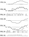
- FIGS.3A to 3G show waveforms in respective portions of the arithmetic unit.
- V1 in FIG.3A and A1 in FIG.3D are voltages which are in direct proportion to voltage and current of the measurement system respectively.
- f(n) in FIG.3C and g(n) in FIG.3F are pulses obtained by delta-modulating V1, A1 respectively. The values of the pulses are limited to only +1 or -1.
- Fa(n) in FIG.3B and Ga(n) in FIG.3E are outputs of the integrators 105, 106 in the first and second 1-bit A/D converters 101, 102, which are coded values of respective input voltages V1, A1.
- n in FIG.3G represents the n -th order in FIGS.3A to 3F.
- the output of the first up-down counter 109 is controlled by f(n) to count up the number of clock ⁇ , the output can be derived as a value Fd which is a digital coded Fa(n). But the (n-1)-th value Fd(n-1) in place of the value Fd(n) would be output in connection with the clock ⁇ .
- FIGS.4a to 4d the meaning of the adding and subtracting calculation will be plainly explained here.
- the above cases (I) to (IV) respectively correspond to FIGS.4a to 4d.
- the portion surrounded by solid lines corresponds to W(n)
- the portion surrounded by dotted lines corresponds to W(n-1).
- the portion with hutch slanting below right corresponds to F(n-1)
- the portion with hutch slanting below left corresponds to G(n-1).
- Addition and subtraction of respective output data Fd(n-1), Gd(n-1) and 1 are controlled by g(n), f(n), h(n) (i.e., EXnor of f(n) and g(n)) respectively.
- the output data of the adder-subtractor 112 can be derived as the value W(n) which is proportional to the product V1 ⁇ A1 of input voltages.
- W(n) is a n-th instantaneous multiplication value of V1, A1
- the adder 114 executes the integral by adding W(n-1) and output data of the adder 114 itself, i.e., an integral value from 1 to (n-2) of W(i) of i.
- an electric energy arithmetic unit for measuring electric energy can be accomplished.
- the electric energy arithmetic unit can be constructed by all hardwares, calculation can be effected without interposition of software incorporated into the CPU, which leads to reduction in size of the CPU. Since very few devices, i.e., only the 1-Bit A/D converters, are needed as the analogue devices, the arithmetic unit can be made small in size if it is manufactured as an LSI, which leads to low cost of the arithmetic unit. In addition, a higher precision operation can be attained in the A/D converter portion if the sampling frequency is made higher.
- an electric power arithmetic unit for measuring electric power can be accomplished.
- the electric energy arithmetic unit or the electric power arithmetic unit can be manufactured at low cost.
- the output W(n) of the adder-subtractor 112 may be used instead of the output W(n-1) of the latch 113 as the input data of the adder 114. Also the same operation and advantages as in the above can be achieved if the delta modulators (1-bit A/D converters 101, 102) consist of delta-sigma modulators.
- FIG.5 shows a configuration of an arithmetic unit according to a second embodiment of the present invention, which can calculate reactive electric power or reactive electric energy.
- a delay circuit 115 is provided between the first 1-bit A/D converter 101 and the first up-down counter 109 in the second embodiment.
- the delay circuit 115 can be, for example, made up of shift register, digital PLL, CCD, etc.
- the delay circuit 115 delays the output f(n) of the first 1-bit A/D converter 101 by a 1/4 phase time of the signal which is input into the terminal T1 (e.g., 5 ms if a frequency of the signal is 50 Hz) and then output the delayed output f(n) as a signal fr(n).
- FIG.6 shows a configuration of an arithmetic unit according to a third embodiment of the present invention.
- a frequency detecting circuit 116 is further added to the configuration of the second embodiment.
- the frequency detecting circuit 116 detects sequentially a frequency of the signal V1 and then supplies resultant information to the delay circuit 115. Because the delay circuit 115 can receive frequency information of the signal V1 from the frequency detecting circuit 116, phase-shift of the signal f(n) can be conducted precisely.
- FIG.7 shows an example of a detailed configuration of the delay circuit 115 in the third embodiment of the present invention.
- the delay circuit 115 comprises a plurality of shift registers 122 connected in serial with each other and operated based on the clock ⁇ as a reference signal, and the output signal f(n) of the first 1-bit A/D converter 101 being input into the first stage of the shift registers; a decoder 121 for decoding the signal output from the frequency detecting circuit 116; a plurality of AND gates 123 having one input terminals for receiving the output signal of the decoder 121 respectively and other input terminals for receiving respective output signals of the plurality of shift registers 122; and an OR gate 124 for receiving respective output signals from the plurality of AND gates 123.
- the AND gates 123 and the OR gate 124 may select the output from the appropriate stage out of the plurality of shift registers 122 and then output the output as the signal fr(n). According to such configuration, even if the frequency of the signal V1 fluctuates, the signal f(n) can be phase-shifted precisely in accordance with frequency information supplied from the frequency detecting circuit 116.
Landscapes
- Physics & Mathematics (AREA)
- General Physics & Mathematics (AREA)
- Engineering & Computer Science (AREA)
- Power Engineering (AREA)
- Analogue/Digital Conversion (AREA)
- Measurement Of Current Or Voltage (AREA)
- Measuring Phase Differences (AREA)
Applications Claiming Priority (3)
| Application Number | Priority Date | Filing Date | Title |
|---|---|---|---|
| JP44877/96 | 1996-03-01 | ||
| JP4487796 | 1996-03-01 | ||
| JP4487796 | 1996-03-01 |
Publications (3)
| Publication Number | Publication Date |
|---|---|
| EP0793106A2 true EP0793106A2 (de) | 1997-09-03 |
| EP0793106A3 EP0793106A3 (de) | 1998-05-20 |
| EP0793106B1 EP0793106B1 (de) | 2004-09-08 |
Family
ID=12703731
Family Applications (1)
| Application Number | Title | Priority Date | Filing Date |
|---|---|---|---|
| EP97103353A Expired - Lifetime EP0793106B1 (de) | 1996-03-01 | 1997-02-28 | Arithmetische Einheit |
Country Status (6)
| Country | Link |
|---|---|
| US (1) | US5924050A (de) |
| EP (1) | EP0793106B1 (de) |
| KR (1) | KR100227203B1 (de) |
| CN (1) | CN1104693C (de) |
| DE (1) | DE69730545T2 (de) |
| TW (1) | TW396276B (de) |
Cited By (2)
| Publication number | Priority date | Publication date | Assignee | Title |
|---|---|---|---|---|
| US6496783B1 (en) | 1999-03-05 | 2002-12-17 | Kabushiki Kaisha Toshiba | Electric power calculation system |
| EP2096450A3 (de) * | 2008-02-28 | 2014-02-19 | Toshiba Toko Meter Systems Co., Ltd. | Stromzähler |
Families Citing this family (9)
| Publication number | Priority date | Publication date | Assignee | Title |
|---|---|---|---|---|
| JP3290946B2 (ja) * | 1998-03-10 | 2002-06-10 | 株式会社東芝 | 電力演算装置 |
| US6417792B1 (en) * | 2000-01-18 | 2002-07-09 | Cirrus Logic, Inc. | Single phase bi-directional electrical measurement systems and methods using ADCs |
| SG118136A1 (en) * | 2002-05-22 | 2006-01-27 | Sylvester Chang Joseph | A digital multiplier with reduced spurious switching by means of latch adders |
| US7079577B2 (en) * | 2004-09-08 | 2006-07-18 | Atmel Corporation | Wide window decoder circuit for dual phase pulse modulation |
| DE102008051421A1 (de) * | 2008-10-11 | 2010-04-15 | Robert Bosch Gmbh | Vorrichtung und Verfahren zur Messung elektrischer Kenngrößen |
| US9201104B2 (en) * | 2012-10-08 | 2015-12-01 | Tyco Electronics Corporation | Intelligent power sensing device |
| US9588152B2 (en) * | 2013-01-09 | 2017-03-07 | Flextronics Ap, Llc | Digital signal processing method for measurement of AC voltage with power converters at light load operation |
| CN110289655B (zh) * | 2019-07-04 | 2020-12-11 | 北京智芯微电子科技有限公司 | 输入电压模式的识别方法 |
| CN118670537B (zh) * | 2024-06-11 | 2026-01-09 | 北京时代民芯科技有限公司 | 一种像元级红外探测器读出电路 |
Family Cites Families (8)
| Publication number | Priority date | Publication date | Assignee | Title |
|---|---|---|---|---|
| US4255707A (en) * | 1979-08-07 | 1981-03-10 | Westinghouse Electric Corp. | Electrical energy meter |
| JPH0821049B2 (ja) * | 1987-09-24 | 1996-03-04 | 株式会社東芝 | 乗算器 |
| US4999799A (en) * | 1989-01-09 | 1991-03-12 | Board Of Governors For Higher Education, State Of Rhode Island And Providence Plantations | Signal processing apparatus for generating a fourier transform |
| GB2239097B (en) * | 1989-12-18 | 1993-08-11 | Gen Electric Co Plc | Electrical power measuring devices |
| JP3022595B2 (ja) * | 1990-11-30 | 2000-03-21 | 日本電気株式会社 | 電子式電力量計 |
| US5349676A (en) * | 1991-02-11 | 1994-09-20 | General Electric Company | Data acquisition systems with programmable bit-serial digital signal processors |
| US5229713A (en) * | 1991-04-25 | 1993-07-20 | General Electric Company | Method for determining electrical energy consumption |
| JP3080207B2 (ja) * | 1993-01-06 | 2000-08-21 | 三菱電機株式会社 | 電子式電力量計 |
-
1997
- 1997-02-25 TW TW086102255A patent/TW396276B/zh not_active IP Right Cessation
- 1997-02-28 KR KR1019970006620A patent/KR100227203B1/ko not_active Expired - Fee Related
- 1997-02-28 US US08/807,729 patent/US5924050A/en not_active Expired - Fee Related
- 1997-02-28 EP EP97103353A patent/EP0793106B1/de not_active Expired - Lifetime
- 1997-02-28 DE DE69730545T patent/DE69730545T2/de not_active Expired - Fee Related
- 1997-03-01 CN CN97104855A patent/CN1104693C/zh not_active Expired - Fee Related
Cited By (3)
| Publication number | Priority date | Publication date | Assignee | Title |
|---|---|---|---|---|
| US6496783B1 (en) | 1999-03-05 | 2002-12-17 | Kabushiki Kaisha Toshiba | Electric power calculation system |
| DE10010545B4 (de) * | 1999-03-05 | 2004-03-25 | Kabushiki Kaisha Toshiba, Kawasaki | Berechnungssystem für elektrische Leistung |
| EP2096450A3 (de) * | 2008-02-28 | 2014-02-19 | Toshiba Toko Meter Systems Co., Ltd. | Stromzähler |
Also Published As
| Publication number | Publication date |
|---|---|
| KR970066577A (ko) | 1997-10-13 |
| EP0793106B1 (de) | 2004-09-08 |
| CN1163436A (zh) | 1997-10-29 |
| US5924050A (en) | 1999-07-13 |
| TW396276B (en) | 2000-07-01 |
| KR100227203B1 (ko) | 1999-10-15 |
| EP0793106A3 (de) | 1998-05-20 |
| DE69730545D1 (de) | 2004-10-14 |
| DE69730545T2 (de) | 2005-09-01 |
| CN1104693C (zh) | 2003-04-02 |
Similar Documents
| Publication | Publication Date | Title |
|---|---|---|
| EP0329381B1 (de) | Unterabtastungsgerät für Datenproben | |
| US5924050A (en) | Arithmetic unit | |
| EP0168220A2 (de) | Verfahren und Einrichtung zur Umwandlung eines Analogsignals in ein Digitalsignal mittels einer Übertastungstechnik | |
| US7292174B2 (en) | Current sensing analog to digital converter and method of use | |
| CN101107760B (zh) | 电流感测模拟-数字转换器和使用方法 | |
| JP3290946B2 (ja) | 電力演算装置 | |
| US6950375B2 (en) | Multi-phase clock time stamping | |
| JP3312006B2 (ja) | 無効電力演算装置及び無効電力量測定装置 | |
| EP1295399B1 (de) | Verfahren und vorrichtung zur erzeugung einer digitalen darstellung aus einem signal | |
| JP3319701B2 (ja) | 演算装置 | |
| US4823293A (en) | Correlation time-difference detector | |
| US6308139B1 (en) | Digital process for determining the effective value of a periodic electric test signal | |
| JPH05333067A (ja) | 電子式電力量計 | |
| EP0858162B1 (de) | Schaltung zur Verarbeitung von pulsbreitenmodulierten Signalen | |
| KR20050043966A (ko) | 평균화를 위한 회로 장치 | |
| RU2093841C1 (ru) | Измерительный преобразователь гармонических составляющих тока и напряжения | |
| Sorensen et al. | Part 1: Optimized sigma-delta modulated current measurement for motor control | |
| US9088294B2 (en) | Apparatus and method for the characterization of analog-to-digital converters | |
| RU2006938C1 (ru) | Интерполятор | |
| EP0922332B1 (de) | Frequenzteilerschaltung | |
| RU1830524C (ru) | Устройство регулировани компенсатора реактивной мощности | |
| RU2028623C1 (ru) | Способ определения постоянной составляющей напряжения | |
| SU1264315A1 (ru) | Многофазный генератор тактовый | |
| SU1575120A1 (ru) | Устройство дл измерени энергии | |
| SU1638653A1 (ru) | Электронный измеритель мощности и энергии |
Legal Events
| Date | Code | Title | Description |
|---|---|---|---|
| PUAI | Public reference made under article 153(3) epc to a published international application that has entered the european phase |
Free format text: ORIGINAL CODE: 0009012 |
|
| 17P | Request for examination filed |
Effective date: 19970228 |
|
| AK | Designated contracting states |
Kind code of ref document: A2 Designated state(s): DE FR |
|
| PUAL | Search report despatched |
Free format text: ORIGINAL CODE: 0009013 |
|
| AK | Designated contracting states |
Kind code of ref document: A3 Designated state(s): DE FR |
|
| 17Q | First examination report despatched |
Effective date: 20030825 |
|
| GRAP | Despatch of communication of intention to grant a patent |
Free format text: ORIGINAL CODE: EPIDOSNIGR1 |
|
| GRAS | Grant fee paid |
Free format text: ORIGINAL CODE: EPIDOSNIGR3 |
|
| GRAA | (expected) grant |
Free format text: ORIGINAL CODE: 0009210 |
|
| AK | Designated contracting states |
Kind code of ref document: B1 Designated state(s): DE FR |
|
| REF | Corresponds to: |
Ref document number: 69730545 Country of ref document: DE Date of ref document: 20041014 Kind code of ref document: P |
|
| PGFP | Annual fee paid to national office [announced via postgrant information from national office to epo] |
Ref country code: FR Payment date: 20050208 Year of fee payment: 9 |
|
| PGFP | Annual fee paid to national office [announced via postgrant information from national office to epo] |
Ref country code: DE Payment date: 20050224 Year of fee payment: 9 |
|
| PLBE | No opposition filed within time limit |
Free format text: ORIGINAL CODE: 0009261 |
|
| STAA | Information on the status of an ep patent application or granted ep patent |
Free format text: STATUS: NO OPPOSITION FILED WITHIN TIME LIMIT |
|
| ET | Fr: translation filed | ||
| 26N | No opposition filed |
Effective date: 20050609 |
|
| PG25 | Lapsed in a contracting state [announced via postgrant information from national office to epo] |
Ref country code: DE Free format text: LAPSE BECAUSE OF NON-PAYMENT OF DUE FEES Effective date: 20060901 |
|
| REG | Reference to a national code |
Ref country code: FR Ref legal event code: ST Effective date: 20061031 |
|
| PG25 | Lapsed in a contracting state [announced via postgrant information from national office to epo] |
Ref country code: FR Free format text: LAPSE BECAUSE OF NON-PAYMENT OF DUE FEES Effective date: 20060228 |