EP0793116A2 - Gerät zur Detektion von vorbeifliegenden Objekten in einem zu überwachenden Raum - Google Patents
Gerät zur Detektion von vorbeifliegenden Objekten in einem zu überwachenden Raum Download PDFInfo
- Publication number
- EP0793116A2 EP0793116A2 EP97103122A EP97103122A EP0793116A2 EP 0793116 A2 EP0793116 A2 EP 0793116A2 EP 97103122 A EP97103122 A EP 97103122A EP 97103122 A EP97103122 A EP 97103122A EP 0793116 A2 EP0793116 A2 EP 0793116A2
- Authority
- EP
- European Patent Office
- Prior art keywords
- light emitting
- plural
- emitting devices
- devices
- flying object
- Prior art date
- Legal status (The legal status is an assumption and is not a legal conclusion. Google has not performed a legal analysis and makes no representation as to the accuracy of the status listed.)
- Withdrawn
Links
- 238000012544 monitoring process Methods 0.000 title claims abstract description 94
- 230000003287 optical effect Effects 0.000 claims abstract description 32
- 238000001514 detection method Methods 0.000 claims abstract description 13
- 238000013459 approach Methods 0.000 claims description 30
- 238000007493 shaping process Methods 0.000 claims description 5
- 238000006243 chemical reaction Methods 0.000 claims description 4
- 238000005259 measurement Methods 0.000 description 5
- 238000010586 diagram Methods 0.000 description 2
- 238000000034 method Methods 0.000 description 2
- 238000000926 separation method Methods 0.000 description 2
- 230000003321 amplification Effects 0.000 description 1
- 238000004891 communication Methods 0.000 description 1
- 238000007689 inspection Methods 0.000 description 1
- 238000003199 nucleic acid amplification method Methods 0.000 description 1
- 230000008520 organization Effects 0.000 description 1
- 230000007704 transition Effects 0.000 description 1
Images




Classifications
-
- G—PHYSICS
- G01—MEASURING; TESTING
- G01S—RADIO DIRECTION-FINDING; RADIO NAVIGATION; DETERMINING DISTANCE OR VELOCITY BY USE OF RADIO WAVES; LOCATING OR PRESENCE-DETECTING BY USE OF THE REFLECTION OR RERADIATION OF RADIO WAVES; ANALOGOUS ARRANGEMENTS USING OTHER WAVES
- G01S17/00—Systems using the reflection or reradiation of electromagnetic waves other than radio waves, e.g. lidar systems
- G01S17/02—Systems using the reflection of electromagnetic waves other than radio waves
- G01S17/04—Systems determining the presence of a target
Definitions
- the present invention relates to an apparatus for detecting that a flying object has passed a monitoring space (hereinafter referred to as a monitoring space passing detecting apparatus), and particularly to a monitoring space passing detecting apparatus which detects that a flying object has passed a monitoring space and transmits the detected information to the flying object, when performing a landing guidance for the flying object such as an aircraft and the like.
- a monitoring space passing detecting apparatus which detects that a flying object has passed a monitoring space and transmits the detected information to the flying object, when performing a landing guidance for the flying object such as an aircraft and the like.
- GPS global positioning system
- MLS microwave landing system
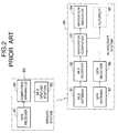
- an MLS signal received by an antenna 71 is reception-processed by an MLS receiver 72 and is converted into such parameter data as angle measurements, namely, an azimuth angle and an elevation angle, and an antenna position of a ground station, and then supplied to a navigation computer 73.
- a GPS signal received by a GPS antenna 77 is reception-processed by a GPS receiver 76, and a receiving point, namely, the position of an aircraft is measured, and the distance from the aircraft to its landing point is computed on the basis of the measured position data and pre-inputted position data of the landing point on a runway, and the computed distance is supplied to the navigation computer 73 as distance data.
- the navigation computer 73 computes the position of the aircraft and computes a deviation of its position from a specified approaching path on the basis of such parameter data as a measured azimuth angle value, a measured elevation angle value, an antenna position of a ground transmitter, and an azimuth angle and an elevation angle of the approaching path, and the distance data supplied from the GPS receiver 76.
- the deviation information is divided into the horizontal and vertical components in relation to a specified path and a distance to the landing point and is displayed on a navigation indicator 74.
- a horizontal situation indicator (HSI) or an electronic horizontal indicator (EHSI) capable of performing a display in the form of a map is used as the navigation indicator 74.
- an autopilot 75 receives deviation data and distance data from the navigation computer 73 and computes a rudder angle necessary for an automatic-pilot control of an aircraft and a control signal necessary for controlling an aileron.
- a positioning error of a GPS is computed by a GPS receiver and a computing apparatus provided on a ground system, and the positioning error information is transmitted to an in-aircraft system by means of an existing communication means.
- the aircraft obtains an exact distance information at any time by correcting a positioning error obtained by a GPS receiver provided on the in-aircraft system by means of a positioning error information transmitted from the ground system.
- this conventional landing guidance system is composed of a ground system 80 and an in-aircraft system 90.
- the ground system 80 is composed of a GPS receiver 81, a computing apparatus 82 and an MLS ground station 83
- the in-aircraft system 90 is composed of an MLS antenna 91, an MLS receiver 92, a navigation computer 93, a navigation indicator 94, an autopilot 95, a GPS receiver 96, and a GPS antenna 97.
- the GPS receiver 81 on the ground obtains position data of the ground system 80 by receiving a signal from a GPS satellite (not illustrated).
- the computing apparatus 82 compares the position data with the pre-stored actual position data of the ground system 80, and transmits a difference between them to the MLS ground station 83 as a positioning error information.
- This positioning error information is used as the respective deviation information in relation to latitude, longitude, height, and the like, and is converted into a specified format as a word of MLS auxiliary data in the MLS ground station 83, and then is sent out within the MLS domain.
- the MLS receiver 92 processes a signal which has been transmitted from the ground system 80 and received by the MLS antenna 91, and outputs deviation information of the received azimuth angle deviated from a reference azimuth angle and that of the received elevation angle deviated from a reference elevation angle, and auxiliary data.
- the deviation data and auxiliary data outputted from the MLS receiver 92 are inputted into the navigation computer 93.
- the position data for representing its own aircraft position obtained by the GPS receiver 96 through the GPS antenna 97 are also inputted into the navigation computer 93.
- the navigation computer 93 compensates the position data supplied from the GPS receiver 96 of the in-aircraft system 90 with a positioning error information, namely, a deviation information and auxiliary data, and outputs its own exact aircraft position to the navigation indicator 94.
- An automatic-pilot control is performed by sending data from the navigation computer 93 to the autopilot 95.
- the system makes it possible for an aircraft to perform a complicated approach and landing such as a segmented approach, a curved approach or the like by combining an MLS with a GPS receiver which is higher in accuracy of a distance measurement and lower in cost in comparison with an existing distance measuring equipment (DME) or a precision distance measuring equipment (DME/P).
- DME distance measuring equipment
- DME/P precision distance measuring equipment
- the course width of the descending path is prescribed to be 210m in the direction perpendicular to the center line of a runway at the end of the runway. That is to say, after an aircraft has passed a space of 15m to 18m in vertical plane width and of 210m in horizontal plane width above the end of a runway, it raises up its fuselage which has been nosing down and comes into a slightly nose-up posture for horizontal landing or main ground gear landing. Namely, a flare-out operation is started. Therefore, the above-mentioned specified space composed of said vertical plane width and said horizontal plane width is an important position for an aircraft which has come into a final landing posture to judge the beginning of a fare-out operation.
- the specified space is treated as a monitoring space in the following.
- a positioning accuracy obtained by a GPS receiver is several ten meters in Clear and Acquisition Code, and is several meters even in case of using Precision Code or a differential GPS mode.
- a system error obtained by an MLS receiver is ⁇ 6m in the horizontal direction, and is ⁇ 0.6m in the vertical direction. Accordingly, an error of height from the ground surface obtained from elevation angle data obtained by the MLS receiver and distance data from the landing point to the own aircraft obtained by the GPS receiver becomes several meters. Therefore, in case of using a GPS only, a detecting accuracy of several centimeters or less in both the horizontal and vertical directions necessary for detecting an aircraft passing the specified space cannot be obtained.
- An object of the present invention is to provide a monitoring space passing detecting apparatus for making it possible to detect in an instant that a flying object has passed a specfied space.
- Another object of the invention is to provide a monitoring space passing detecting apparatus for making it possible to detect in an instant that a flying object has passed a specified space and transmit the passing information to the aircraft.
- Another object of the invention is to provide a monitoring space passing detecting apparatus for making it possible to prevent an erroneous operation caused by an external disturbing light when detecting that a flying object has passed a specified space.
- a monitoring space passing detecting apparatus comprises plural light emitting device groups including plural light emitting devices which are arranged in the direction perpendicular to the center line of a runway and whose light emitting angles are different from one another; a first controller for controlling said plural light emitting device groups so that light emitting devices having the same light emitting angle as each other included, respectively, in said plural light emitting device groups may emit light at the same time and light emitting devices having different light emitting angles from one another included, respectively, in said plural light emitting device groups may emit light one after another; plural light receiving device groups including plural light receiving devices which are arranged, respectively, so as to correspond to said plural light emitting devices included, respectively, in said plural light emitting device groups and which receive the reflected lights by reflection of the lights emitted frog said plural light emitting devices on a flying object passing a monitoring space set in advance; a second controller for controlling said plural light receiving device groups so that light receiving devices which receive the reflected lights corresponding to the lights e
- plural light emitting device groups each of which is composed of plural light emitting devices having light emitting angles of ⁇ 1 to ⁇ n so as to cover, from the upper limit to the lower limit, monitoring spaces intermittently or consecutively set in advance so as to include at least the lowest approach height above a landing approach path for an aircraft are arranged in the direction perpendicular to an extension line of the center line of a runway.
- the light emitting angles ⁇ 1 to ⁇ n are set in advance at the respective values obtained by dividing the vertical width from the upper limit to the lower limit of the monitoring space so as not to cause omission of detection of an aircraft. Thanks to that light emitting angles of plural light emitting device included in plural light emitting device groups are set at these light emitting angles ⁇ 1 to ⁇ n, the monitoring space can be electronically scanned from the upper limit to the lower limit at a proper speed.
- And arrangement of the light receiving device groups is geometrically computed and set in advance so that omission of detection may not happen for an acceptable inclination of an aircraft at the time of a landing approach which inclination is prescribed in the technical standards of ICAO Annex 10. And light receiving devices having wide beam width are adopted so as to receive reflected lights by diffuse reflection from an aircraft.
- these light receiving devices are controlled so that only a pulse modulator group and a pulse receiver group in which pulse modulators and pulses receivers, respectively, are paired with each other may operate in order to prevent an erroneous operation caused by an external disturbing light.
- Said detected result namely, the information of detecting that an aircraft has passed the upper or the lower limit of the monitoring space is transmitted to the aircraft at an instant by a transmitter.
- a specified space composed of the product of a horizontal width and a vertical width including the main positions such as the lowest approach height (decision height), a reference datum, a flare-out height, a decrab height, and the like is set as a monitoring space on a landing approach path to be monitored as described above and such specified spaces are intermittently or consecutively formed, then it is possible to transmit in an instant a monitoring space passing information to the aircraft and compensate for accuracy of a three-dimensional measurement by a GPS with that information, and therefore, a high-category approach by means of a GPS can be performed under a bad weather.
- a reference datum means a point at a specified height [15m (50ft) + 3m (10ft)] located above the intersection of the runway center line and the threshold and through which the downward extended straight portion of the instrument landing system (ILS) glide path passes.
- a flare-out means an operation of raising up an airframe which has been descending in a nose-down posture for landing, and making the airframe assume a slightly nose-up posture for a horizontal landing or for the main ground gear to touch the ground. And a height where this operation is started is called a flare-out starting height.
- a decrab operation means a pilot operation of directing the nose of an aircraft just toward the runway direction immediately before touching the ground surface, although the aircraft continues to descend ordinarily as keeping its nose directed toward the wind in case that the aircraft attempts to land as receiving a side wind. And a height where this operation is started is called a decrab starting height.
- a monitoring space passing detecting apparatus of this embodiment is provided with a pulse generator 1, a switcher 2 comprising plural gate circuits 2a to 2n, a pulse modulator 3 comprising plural pulse modulators 3a to 3n, a light emitter 4 comprising plural light emitting device groups 4a to 4n, a light receiver 5 comprising plural light receiving device groups 5a to 5n, an optical receiver 6 comprising plural optical receivers 6a to 6n, a detector 7 comprising plural OR gate circuits 7a to 7n, a gate scanning controller 8, and a transmitter comprising a transmitter 9 and an antenna 10.
- a pulse generator 1 comprising plural gate circuits 2a to 2n
- a pulse modulator 3 comprising plural pulse modulators 3a to 3n
- a light emitter 4 comprising plural light emitting device groups 4a to 4n
- a light receiver 5 comprising plural light receiving device groups 5a to 5n
- an optical receiver 6 comprising plural optical receivers 6a to 6n
- a detector 7 comprising plural OR gate circuits 7a
- a monitoring space E has the upper limit defined by a line segment AB and the lower limit defined by a line segment CD. And the monitoring space E is defined in size by a horizontal width W and a vertical width H0.
- the light emitting device groups 4a to 4n of the light emitter 4 are arranged in the direction perpendicular to an extension line of the center line of a runway 11, and furthermore, are arranged at the positions computed in advance so that they may have light emitting angles of ⁇ 1 to ⁇ n for a range from the upper limit A-B (line segment AB) to the lower limit C-D (line segment CD) of the monitoring space E.
- a light emitting device group 4-i of the light emitter 4 has a light emitting array module structure in which light emitting devices 4a-i to 4n-i are arranged in the shape of an array. That is to say, the light emitting device 4a-i is set in advance so that its optical axis may make a light emitting angle ⁇ 1, and the light emitting device 4n-i is set in advance so that its optical axis may make a light emitting angle ⁇ n.
- the light emitting angle ⁇ 1 is an angle set in order to electronically scan the upper limit A-B of the monitoring space E and the light emitting angle ⁇ n is an angle set in order to electronically scan the lower limit C-D of the monitoring space E.
- Light emitting device groups 4-i of, a module structure are arranged on the surface of the ground at proper intervals in the direction perpendicular to the center line of the runway 11. For example, the light emitting device groups 4-i are embedded in the end part of the runway 11, namely, in a threshold.
- an interval d1 in the Y-axis direction between the light emitting devices 4a-i arranged in the plural light emitting device groups 4-i is zero, actually it will do that the interval is about one-tenth of the wing width WS of the minimum aircraft to be detected in the monitoring space E.
- an interval dn in the Y-axis direction between the light emitting devices 4n-i arranged in plural light emitting device groups 4-i is zero, actually it will do that the interval is about one-tenth of the wing width WS of the minimum aircraft to be detected in the monitoring space E.
- an interval _d in the Y-axis direction between the light emitting devices in a light emitting device group 4-i, for example, between light emitting devices 4a-1 and 4b-1, between light emitting devices 4b-1 and 4c-1, - - -, or between 4(n-1)-1 and 4n-1 in the light emitting device group 4-1 is zero, actually it will do that the interval is about one-tenth of the vertical width TS of the minimum aircraft to be detected in the monitoring space E.
- Plural pulse modulators 3a to 3n of the pulse modulator 3 perform an automatic control so that output of the light emitter 4 may be kept constant and generate synchronizing pulses 101a to 101n.
- the plural pulse modulators 3a to 3n are respectively composed of pulse modulators 3a-i to 3n-i corresponding to the respective light emitting devices 4a-i to 4n-i and the pulse modulators 3a-i to 3n-i generates, respectively, synchronising pulses 101a-i to 101n-i.
- Plural gate circuits 2a to 2n of the switcher 2 perform an on-off control of input signals to the pulse modulators 3a to 3n respectively corresponding to the gate circuits.
- the plural gate circuits 2a to 2n are respectively composed of gate circuits 2a-i to 2n-i respectively corresponding to the light emitting devices 4a-i to 4n-i.
- the pulse generator 1 applies pulse input signals 100a to 100n which are different in frequency from one another, respectively, to the plural gate circuits 2a to 2n of the switcher 2.
- the gate scanning controller 8 outputs gate scanning control signals 104a to 104n, respectively, to the plural gate circuits 2a to 2n of the switcher 2, in order to electronically scan outputs toward the space from the light emitting devices 4a-i to 4n-i of the light emitter 4 over a range from the upper limit A-B to the lower limit C-D of the monitoring space E at a proper speed.
- the plural light receiving device groups 5a to 5n of the light receiver 5 are arranged in the direction perpendicular to an extension line of the center line of the runway 11 as considering an acceptable inclination ⁇ _ ⁇ 1 of an aircraft 12 in advance so as to effectively receive the diffuse reflected lights 103a to 103n from the aircraft 12 passing the monitoring space E.
- the plural light receiving device groups 5a to 5n are, respectively, composed of the light receiving devices 5a-i to 5n-i, respectively, corresponding to the light emitting devices 4a-i to 4n-i.
- the plural light receivers 6a to 6n of the light receiver 4 obtain digital outputs by performing a current-voltage conversion of outputs from the plural light receiving device groups 5a to 5n and then performing amplification, filter-separation, rectification, waveform shaping, and comparison of those converted signals.
- the plural light receivers 6a to 6n are, respectively, composed of the light receivers 6a-i to 6n-i, respectively, corresponding to the light receiving devices 5a-i to 5n-i.
- the plural OR gate circuits 7a to 7n of the detector 7 output detection signals 105a to 105n for showing that the aircraft 12 has passed the monitoring space E to the transmitter 9 when at least one of outputs of the plural light receivers 6a to 6n has been changed.
- the transmitter 9 transmits a monitoring space E passing information on the basis of the detection signals 105a to 105n, respectively, from the plural OR gate circuits 7a to 7n to the aircraft 12 through the antenna 10.
- the pulse generator 1 generates pulse input signals 100a to 100n different in frequency from one another, and outputs the pulse input signals 100a to 100n, respectively, to the plural gate circuits 2a to 2n.
- the plural gate circuits 2a to 2n are controlled by the gate scanning control signals 104a to 104n from the gate scanning controller 8 in order to scan the monitoring space E from its upper limit A-B to its lower limit C-D at proper stepping intervals computed in advance from the size of the aircraft 12.
- the plural gate circuits 2a to 2n are controlled by the gate scanning control signals 104a to 104n from the gate scanning controller 8 so as to output the pulse input signals 100a to 100n from the pulse generator 1, respectively, to the plural pulse modulators 3a to 3n at proper stepping intervals.
- the plural pulse modulators 3a to 3n pulse-drive the plural light emitting device groups 4a to 4n corresponding to them with the pulse input signals from the pulse generator 1 inputted from the plural gate circuits 2a to 2n at proper stepping intervals, and send out the synchronizing pulses 101a to 101n to the plural corresponding light receivers 6a to 6n.
- the light emitting devices having the same light emitting angle as each other included, respectively, in the plural light emitting device groups 4a to 4n are controlled so as to emit light at the same time, and the light emitting devices having different light emitting angles from each other included, respectively, in the plural respective light emitting device groups 4a to 4n are controlled so as to emit light one after another.
- An erroneous operation caused by an external disturbing light can be prevented by controlling the pulse modulators and the optical receivers so that only a pulse modulator and an optical receiver which are paired with each other can be operated, namely, for example, only a pair of the pulse modulator 3a and the optical receiver 6a, a pair of the pulse modulator 3b and the optical receiver 6b, - - -, and a pair of the pulse modulator 3n and the optical receiver 6n can be operated.
- Outputs of the plural pulse modulators 3a to 3n are emitted into the monitoring space E over a range from the upper limit A-B to the lower limit C-D at a proper scanning speed and in proper scanning steps, respectively, through the light emitting device groups 4a to 4n.
- the plural light emitting device groups 4a to 4n and the plural light receiving device groups 5a to 5n are arranged in the direction perpendicular to an extension line of the center line of the runway 11, and are arranged at the positions computed in advance so that the light emitting angles from the plural light emitting device groups 4a to 4n and the incident angles and the reflection angles on the aircraft 12 may be, respectively, ⁇ 1 to ⁇ n.
- the pulse-modulated light 102a-1 emitted at a light emitting angle of ⁇ 1 from the light emitting device 4a-1 is hit on the aircraft 12 at an incident angle of ⁇ 1 and is reflected on the aircraft 12 at a reflection angle of ⁇ 1.
- the reflected light 103a from the aircraft 12 is received by the light receiving device 5a-1 near a point at a distance 11 from the intersecting point of the vertical axis of the aircraft 12 and the runway 11.
- the pulse-modulated light 102a-1 emitted at a light emitting angle of ⁇ 1 from the light emitting device 4a-1 is hit on the aircraft 12 at an incident angle of " ⁇ 1 + _ ⁇ 1" and is reflected on the aircraft at a reflection angle of " ⁇ 1 + _ ⁇ 1".
- the reflected light 103a from the aircraft 12 is received by the light receiving device 5a-1 near a point at a distance of H1 x tan ( ⁇ 1 + 2 _ ⁇ 1) from the intersecting point of the vertical axis of the aircraft 12 and the runway 11.
- the pulse-modulated light 102a-1 emitted at a light emitting angle of ⁇ 1 from the light emitting device 4a-1 is hit on the aircraft 12 at an incident angle of " ⁇ 1 - _ ⁇ 1" and is reflected on the aircraft at a reflection angle of " ⁇ 1 - _ ⁇ 1"
- the reflected light 103a from the aircraft 12 is received by the light receiving device 5a-1 near a point at a distance of H1 x tan( ⁇ 1 - 2 _ ⁇ 1) from the intersecting point of the vertical axis of the aircraft 12 and the runway 11.
- an acceptable inclination of the aircraft 12 is prescribed to be within ⁇ 20 degrees in the standards and the flight inspection rules of ICAO Annex 10.
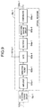
- the pulse modulator 3a-1 is provided with a switching circuit 30a-1, a built-in light receiving device 31a-1, a buffer 32a-1, a peak hold circuit 33a-1, a reference voltage 34a-1, a differential amplifier 35a-1, and a light emitting device driving circuit 36a-1.
- a pulse input signal 100a supplied from the pulse generator 1 through the gate circuit 2a-1 is inputted into the switching circuit 30a-1 for the light emitting device 4a-1 composed of a laser diode or the like.
- the switching circuit 30a-1 turns on or off the light emitting device 4a-1 according to the inputted pulse input signal 100a.
- the peak hold circuit 33a-1 holds a peak level obtained through the buffer 32a-1 when the light emitting device 4a-1 is on.
- the differential amplifier 35a-1 takes in the peak level held by the peak hold circuit 33a-1 and a reference voltage 34a-1 set in advance as input and outputs a differential output of them as an input signal to the light emitting device driving circuit 36a-1.
- the system is always given a feedback when the light emitting device groups 4a to 4n are turned on and so the emitted lights from the light emitting device groups 4a to 4n are stabilized in level.
- the other pulse modulators 3a-2 to 3a-m, - - -, 3n-1 to 3n-m have also the same composition as the said pulse modulator 3a-1, and operate in the same way as the pulse modulator 3a-1.
- the optical receiver 6a-1 is provided with an amplifier 61a-1, a band-pass filter 62a-1, a gate 63-1a, a rectifier 64a-1, a waveform shaping circuit 65a-1, and a comparator 66a-1.
- the optical receiver 6a-1 performs a current-voltage conversion of output from the light receiving device 5a-1, amplifies the converted signal up to a necessary level by means of the amplifier 61a-1, and then performs a frequency-separation of the amplified signal by means of the band-pass filter 62a-1.
- the gate 63a-1 outputs the signal separated in frequency by the band-pass filter 62a-1 to the rectifier 64a-1, synchronously with the synchronizing pulse 101a-1 inputted from the pulse modulator 3a-1.
- a signal outputted from the gate 63a-1 is full-wave-rectified by the rectifier 64a-1, is waveform-shaped by the waveform shaping circuit 65a-1, and then is converted into a digital output 106a-1 by the comparator 66a-1.
- the other optical receivers 6a-2 to 6a-m, - - -, 6n-1 to 6n-m have also the same composition as the said optical receiver 6a-1, and operate in the same way as the said optical receiver 6a-1.
- both of a glide pass 22 and an ideal trajectory 23 of the wheels are shown on the final approach path.
- the decision height means the lowest height up to which an aircraft can descend by an instrument flight in case of performing a precise approach, namely, the lowest height required for obtaining an instruction necessary for continuing the final approach.
- the decision height of category I means that this lowest height is equal to or higher than 60m (200ft)
- the decision height of category II means that this lowest height is equal to or higher than 30m (100ft) and lower than 60m (200ft).
- a pilot In case of the decision height of category I, a pilot must visually recognize the runway 11 at a height of 60m (200ft) or higher from the runway 11, and if the pilot cannot visually recognize it, the pilot gives up the landing.
- a pilot In case of the decision height of category II, a pilot must visually recognize the runway 11 at a height which is equal to or higher than 30m (100ft) and lower than 60m (200ft) from the runway 11, and if the pilot cannot visually recognize it, the pilot gives up the landing.
- a monitoring space passing detecting apparatus sets monitoring spaces 28a to 28f, respectively, for the above-mentioned heights, and monitoring space passing detecting apparatuses as described above are arranged, respectively, for those monitoring spaces 28a to 28f.
- the reference number 27 shows an extension line of the center line 21 of the runway 11.
- the horizontal width of the monitoring space 28a at the decision height of category I is set at a course width 24 of a localizer prescribed in the existing ILS, and the vertical width of the monitoring space 28c at the reference datum 20c is set at "15m +3 to -0m".
- the horizontal width 26 of the monitoring space 28c is 210m (700ft).
- the horizontal widths of the monitoring spaces 28d and 28f in relation to another fare-out guidance are set so as to be matched with the course width 24, and the vertical widths of the monitoring spaces 28d and 28f are set at a proper width.
- the plural light emitting device groups 4a to 4n and the plural light receiving device groups 5a to 5n, respectively, corresponding to the groups 4a to 4n are arranged in the positions computed in advance in the direction perpendicular to the extension line 27 of the center line 21 of the runway 11 so that the light emitting angles of the plural light emitting device groups 4a to 4n and the incident angles of lights to the aircraft 12 and the angles of reflection from the aircraft 12 may be, respectively, ⁇ 1 to ⁇ n.
- the plural optical receivers 6a to 6n, respectively, corresponding to the plural light receiving device groups 5a to 5n take in outputs of the plural light receiving device groups 5a to 5n as input, and output digital signals to the OR gate circuits 7a to 7n, respectively, corresponding to the plural optical receivers 6a to 6n.
- detection signals 105a to 105n to show that an aircraft 12 has passed a monitoring space are outputted to the transmitter 9 from the plural OR gate circuits 7a to 7n, respectively, corresponding to the plural light receiving device groups 5a to 5n.
- the monitoring spaces 28a to 28f including the main positions such as the lowest approach heights (decision heights: a decision height of category I 20a and a decision height of category II 20b), a reference datum 20c, a flare-out height, and a decrab height intermittently or consecutively on the landing approach path, to detect in an instant an aircraft 12 passing the monitoring spaces 28a to 28f, and to transmit the passing information to the aircraft 12.
- the monitoring spaces 28a to 28f including the main positions intermittently or consecutively on the landing approach path, it is possible to transmit in an instant a monitoring space passing information to the aircraft 12, compensate for accuracy of a three-dimensional measurement by a GPS with that information, and perform a high-category approach by the GPS under a bad weather.
- the plural light emitting device groups 4a to 4n and the plural light receiving device groups 5a to 5n which are paired with each other are, respectively, driven synchronously with each other and each of the pairs of the plural light emitting devices 4a-i to 4n-i which have the same light emitting angle as each other among the light emitting angles ⁇ 1 to ⁇ n uses a pulse-modulated light different in frequency from the other pairs, they are little influenced by an external disturbing light.
- the reflected lights 103a to 103n given by that the pulse-modulated lights 102a to 102n emitted from the plural light emitting device groups 4a to 4n are reflected on the aircraft 12 are detected on the basis of whether or not there is an input signal into the plural light receiving device groups 5a to 5n which are arranged in the direction perpendicular to the extension line 27 of the center line 21 of the runway 11 so that each of them may be symmetrical to and may be paired with one of the plural light emitting device groups 4a to 4n, a vertical structure is unnecessary and it is possible to easily satisfy various prescriptions for a landing zone, an approach surface, a transition surface and the like which are prescribed in the ICAO Annex 10.
- a monitoring space passing detecting apparatus of the invention combined with a GPS to a landing guidance system for an aircraft, it is possible to compensate for accuracy of a three-dimensional measurement by the GPS with the passing information and perform a high-category approach by the GPS under a bad weather.
Landscapes
- Physics & Mathematics (AREA)
- Electromagnetism (AREA)
- Engineering & Computer Science (AREA)
- Computer Networks & Wireless Communication (AREA)
- General Physics & Mathematics (AREA)
- Radar, Positioning & Navigation (AREA)
- Remote Sensing (AREA)
- Traffic Control Systems (AREA)
- Optical Radar Systems And Details Thereof (AREA)
- Geophysics And Detection Of Objects (AREA)
Applications Claiming Priority (2)
| Application Number | Priority Date | Filing Date | Title |
|---|---|---|---|
| JP8040222A JP2743905B2 (ja) | 1996-02-28 | 1996-02-28 | 監視空間通過検出装置 |
| JP40222/96 | 1996-02-28 |
Publications (2)
| Publication Number | Publication Date |
|---|---|
| EP0793116A2 true EP0793116A2 (de) | 1997-09-03 |
| EP0793116A3 EP0793116A3 (de) | 1999-06-02 |
Family
ID=12574740
Family Applications (1)
| Application Number | Title | Priority Date | Filing Date |
|---|---|---|---|
| EP97103122A Withdrawn EP0793116A3 (de) | 1996-02-28 | 1997-02-26 | Gerät zur Detektion von vorbeifliegenden Objekten in einem zu überwachenden Raum |
Country Status (3)
| Country | Link |
|---|---|
| US (1) | US5825021A (de) |
| EP (1) | EP0793116A3 (de) |
| JP (1) | JP2743905B2 (de) |
Cited By (2)
| Publication number | Priority date | Publication date | Assignee | Title |
|---|---|---|---|---|
| FR2925712A1 (fr) * | 2007-12-21 | 2009-06-26 | Thales Sa | Procede pour l'aide a l'atterrissage d'aeronef utilisant un gps et un mls dans le cadre d'une approche axiale calculee. |
| CN105301574A (zh) * | 2015-11-11 | 2016-02-03 | 中国科学院半导体研究所 | 避免水下激光测探器被杂散光损伤的装置 |
Families Citing this family (19)
| Publication number | Priority date | Publication date | Assignee | Title |
|---|---|---|---|---|
| US8203486B1 (en) | 1999-03-05 | 2012-06-19 | Omnipol A.S. | Transmitter independent techniques to extend the performance of passive coherent location |
| US7570214B2 (en) | 1999-03-05 | 2009-08-04 | Era Systems, Inc. | Method and apparatus for ADS-B validation, active and passive multilateration, and elliptical surviellance |
| US7777675B2 (en) | 1999-03-05 | 2010-08-17 | Era Systems Corporation | Deployable passive broadband aircraft tracking |
| US7667647B2 (en) | 1999-03-05 | 2010-02-23 | Era Systems Corporation | Extension of aircraft tracking and positive identification from movement areas into non-movement areas |
| US8446321B2 (en) | 1999-03-05 | 2013-05-21 | Omnipol A.S. | Deployable intelligence and tracking system for homeland security and search and rescue |
| US7612716B2 (en) | 1999-03-05 | 2009-11-03 | Era Systems Corporation | Correlation of flight track data with other data sources |
| US7739167B2 (en) | 1999-03-05 | 2010-06-15 | Era Systems Corporation | Automated management of airport revenues |
| US7782256B2 (en) | 1999-03-05 | 2010-08-24 | Era Systems Corporation | Enhanced passive coherent location techniques to track and identify UAVs, UCAVs, MAVs, and other objects |
| US7908077B2 (en) | 2003-06-10 | 2011-03-15 | Itt Manufacturing Enterprises, Inc. | Land use compatibility planning software |
| US7889133B2 (en) | 1999-03-05 | 2011-02-15 | Itt Manufacturing Enterprises, Inc. | Multilateration enhancements for noise and operations management |
| US6658572B1 (en) * | 2001-10-31 | 2003-12-02 | Secure Sky Ventures International Llc | Airline cockpit security system |
| US7428450B1 (en) * | 2003-12-16 | 2008-09-23 | Garmin International, Inc | Method and system for using a database and GPS position data to generate bearing data |
| FR2869419B1 (fr) * | 2004-04-22 | 2006-06-30 | Airbus France Sas | Procede et dispositif d'aide a l'atterrissage d'un aeronef sur une piste d'atterrissage |
| US7965227B2 (en) | 2006-05-08 | 2011-06-21 | Era Systems, Inc. | Aircraft tracking using low cost tagging as a discriminator |
| US7679528B1 (en) | 2006-07-28 | 2010-03-16 | Rockwell Collins, Inc. | Modulation of aircraft guidance lights |
| JP5177398B2 (ja) * | 2008-04-08 | 2013-04-03 | 株式会社津村総合研究所 | 移動体案内装置 |
| CN103646384B (zh) * | 2013-12-20 | 2016-06-22 | 江苏大学 | 一种遥感扫描成像平台飞行速度的优化方法 |
| KR101645869B1 (ko) * | 2015-04-13 | 2016-08-05 | 주식회사 알피원 | 신호 발생기를 포함하는 비행체 관제용 송신장치 |
| US10304342B2 (en) | 2016-11-08 | 2019-05-28 | Ge Aviation Systems Llc | Ground-based data acquisition system |
Family Cites Families (8)
| Publication number | Priority date | Publication date | Assignee | Title |
|---|---|---|---|---|
| US4952911A (en) * | 1988-05-18 | 1990-08-28 | Eastman Kodak Company | Scanning intrusion detection device |
| US5144315A (en) * | 1989-02-10 | 1992-09-01 | Cardion, Inc. | System for accurately monitoring aircraft position during training exercises |
| JPH02287900A (ja) * | 1989-04-28 | 1990-11-27 | Japan Radio Co Ltd | Mls機上装置 |
| JPH0419297A (ja) * | 1990-05-10 | 1992-01-23 | Yoshitaka Kindo | 空中滑走路 |
| US5407149A (en) * | 1991-05-30 | 1995-04-18 | Singhai; Tara C. | Devices and means to engage in indoor flight of radio controlled model aircrafts |
| JPH0572317A (ja) * | 1991-09-13 | 1993-03-26 | Japan Radio Co Ltd | 着陸誘導システム |
| JP2779380B2 (ja) * | 1994-07-28 | 1998-07-23 | セイコープレシジョン株式会社 | 測距装置 |
| US8957938B2 (en) | 2009-10-28 | 2015-02-17 | Alcatel Lucent | Method and apparatus for handing over a video conversation from packet switch domain to circuit switch domain |
-
1996
- 1996-02-28 JP JP8040222A patent/JP2743905B2/ja not_active Expired - Lifetime
-
1997
- 1997-02-26 EP EP97103122A patent/EP0793116A3/de not_active Withdrawn
- 1997-02-26 US US08/806,476 patent/US5825021A/en not_active Expired - Fee Related
Cited By (4)
| Publication number | Priority date | Publication date | Assignee | Title |
|---|---|---|---|---|
| FR2925712A1 (fr) * | 2007-12-21 | 2009-06-26 | Thales Sa | Procede pour l'aide a l'atterrissage d'aeronef utilisant un gps et un mls dans le cadre d'une approche axiale calculee. |
| WO2009083507A1 (fr) * | 2007-12-21 | 2009-07-09 | Thales | Procede pour l'aide a l'atterrissage d'aeronef utilisant un gps et un mls dans le cadre d'une approche axiale calculee |
| US8290644B2 (en) | 2007-12-21 | 2012-10-16 | Thales | Method for aircraft landing assistance using GPS and MLS in case of calculated axial approach |
| CN105301574A (zh) * | 2015-11-11 | 2016-02-03 | 中国科学院半导体研究所 | 避免水下激光测探器被杂散光损伤的装置 |
Also Published As
| Publication number | Publication date |
|---|---|
| JP2743905B2 (ja) | 1998-04-28 |
| JPH09230026A (ja) | 1997-09-05 |
| EP0793116A3 (de) | 1999-06-02 |
| US5825021A (en) | 1998-10-20 |
Similar Documents
| Publication | Publication Date | Title |
|---|---|---|
| US5825021A (en) | Apparatus for detecting that a flying object has passed a monitoring space | |
| US5218360A (en) | Millimeter-wave aircraft landing and taxing system | |
| US5235513A (en) | Aircraft automatic landing system | |
| US4853700A (en) | Indicating system for warning airspace or threatening aircraft in aircraft collision avoidance system | |
| RU2100820C1 (ru) | Прецизионная система посадки для наведения самолета вдоль заданной посадочной траектории в пределах радиуса действия наземного запросчика (варианты) | |
| US5724125A (en) | Determination of wind velocity using a non-vertical LIDAR scan | |
| US4133503A (en) | Entry, display and use of data employed to overcome aircraft control problems due to wind shear | |
| US3355733A (en) | Designated area instrument landing system | |
| CN1216299C (zh) | 有关目标定位的改进 | |
| US4925303A (en) | Aircraft piloting aid laser landing system | |
| US4667196A (en) | Active visual display system for remote three-axis flight path guidance of landing aircraft | |
| US3716855A (en) | Glideslope position detection system for use with an independent aircraft landing monitor | |
| RU2516244C2 (ru) | Способ посадки вертолета и устройство для его осуществления | |
| JPS63500678A (ja) | 計器着陸システム | |
| US5206654A (en) | Passive aircraft monitoring system | |
| IL205885A (en) | Method and system for assisting in the landing or the decking of a light aircraft | |
| CN107505625A (zh) | 一种飞行器探测方法 | |
| JPH0524589A (ja) | 垂直離着陸航空機の自動着陸誘導方法 | |
| RU2559196C1 (ru) | Способ захода на посадку летательного аппарата и система для его осуществления | |
| US20240005804A1 (en) | System for determining the position of an autonomous or automated aircraft during its approach to a landing site | |
| US20220413128A1 (en) | Guidance system for leading an aircraft to a reference point; associated guidance method | |
| US3819914A (en) | Device for the flight guidance from a wireless guide beam | |
| US3505676A (en) | Navigation system | |
| RU2055785C1 (ru) | Способ посадки самолета | |
| US4203665A (en) | Aerial surveying method to determine ground contours |
Legal Events
| Date | Code | Title | Description |
|---|---|---|---|
| PUAI | Public reference made under article 153(3) epc to a published international application that has entered the european phase |
Free format text: ORIGINAL CODE: 0009012 |
|
| AK | Designated contracting states |
Kind code of ref document: A2 Designated state(s): DE FR GB |
|
| PUAL | Search report despatched |
Free format text: ORIGINAL CODE: 0009013 |
|
| AK | Designated contracting states |
Kind code of ref document: A3 Designated state(s): DE FR GB |
|
| 17P | Request for examination filed |
Effective date: 19990421 |
|
| 17Q | First examination report despatched |
Effective date: 20020704 |
|
| STAA | Information on the status of an ep patent application or granted ep patent |
Free format text: STATUS: THE APPLICATION IS DEEMED TO BE WITHDRAWN |
|
| 18D | Application deemed to be withdrawn |
Effective date: 20030115 |