EP0793578B1 - Roulette - Google Patents
Roulette Download PDFInfo
- Publication number
- EP0793578B1 EP0793578B1 EP95939354A EP95939354A EP0793578B1 EP 0793578 B1 EP0793578 B1 EP 0793578B1 EP 95939354 A EP95939354 A EP 95939354A EP 95939354 A EP95939354 A EP 95939354A EP 0793578 B1 EP0793578 B1 EP 0793578B1
- Authority
- EP
- European Patent Office
- Prior art keywords
- tubular portion
- castor
- ring
- limbs
- central aperture
- Prior art date
- Legal status (The legal status is an assumption and is not a legal conclusion. Google has not performed a legal analysis and makes no representation as to the accuracy of the status listed.)
- Expired - Lifetime
Links
Images


Classifications
-
- B—PERFORMING OPERATIONS; TRANSPORTING
- B60—VEHICLES IN GENERAL
- B60B—VEHICLE WHEELS; CASTORS; AXLES FOR WHEELS OR CASTORS; INCREASING WHEEL ADHESION
- B60B33/00—Castors in general ; Anti-clogging castors
- B60B33/0028—Construction of wheels; methods of assembling on axle
-
- B—PERFORMING OPERATIONS; TRANSPORTING
- B60—VEHICLES IN GENERAL
- B60B—VEHICLE WHEELS; CASTORS; AXLES FOR WHEELS OR CASTORS; INCREASING WHEEL ADHESION
- B60B2200/00—Type of product being used or applied
- B60B2200/40—Articles of daily use
- B60B2200/43—Carts
- B60B2200/432—Shopping carts
Definitions
- This invention relates to castors, in particular, to castors which may be used on a moving walkway.
- It comprises a fork having two limbs depending from a bridgepiece, two relatively rotatable discs journalled on an axle which is mounted on and which extends between the limbs, each disc having an annular disc portion and a central aperture.
- the bearings for the discs are spaced axially from one another on the axle and are separated by a larger diameter cylindrical part of the axle which is surrounded by a loose fitting brake ring which will hang on that cylindrical part without touching the ground when the castor is running on a flat floor whereas it is pressed into frictional engagement with the walkway by the cylindrical part when the rims of the discs drop into grooves of that walkway.
- the grooved surface need not be formed by a moving walkway.
- a static length of a similar surface is often provided in the region of an exit from a supermarket in order to trap the wheels of a shopping trolley so as to inhibit shopping trolleys being taken out of the supermarket by customers. This is known as a trolley trap.
- GB-A-1416992, US-A-3822437 and US-A-3894310 each show a twin wheel castor which has a body by which it is attached to structure it is to support for pivoting relative thereto about a vertical axis.
- the two wheels are rotatably mounted on a portion of the body of the castor which is disposed between them.
- the wheels include integral hollow spigots which fit one within the other. These spigots are, in turn, received in a further spigot which is formed integrally within the portion of the body between the wheels, these castors are designed for light-weight duties such as at the feet of television cabinets or other such furniture which normally is stationary. They are not sufficiently structurally robust for heavy duty applications such as for shopping trolleys.
- An object of the present invention is to provide a castor for use on a moving walkway or to be trapped by a trolley trap which is simple and cheap to manufacture.
- a castor comprising a fork having two limbs depending from a bridgepiece and two relatively rotatable discs journalled on an axle which is mounted on and which extends between the limbs, each disc having an annular disc portion and a central aperture, wherein the two discs together from a single wheel and the central aperture of each disc is formed by a respective axially projecting tubular portion, one of the tubular portions extending over a major part of the spacing between the limbs and being supported along its axial length by a bearing for rotation of the single wheel on the axle, the other tubular portion being supported along a substantial part of its length by said one tubular portion which provides a plain bearing support for said other tubular portion and which allows rotation on the axle of one of the discs relative to the other.
- the tubular portions are snap-fitted together, with one such portion having a male snap means and the other portion having female snap means which are interengaged with the male snap means.
- the axle may be a nut and a bolt.
- the bearing for rotation of the respective disc on the axle may be a roller bearing.
- each tubular portion adjacent the annular disc portion, sized and positioned so that when said roller bearing is positioned inside the tubular portions it is encapsulated therein, but the axle can pass through its central aperture.
- the coned ring may be arranged to act as a Belleville washer.
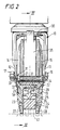
- Figures 1 and 2 show a castor which comprises a fork 10 carrying an axle 11 which extends through an aperture in both limbs 12 and 13 of the fork 10 and by which two discs 14 and 15 are mounted on the fork 10.
- the axle 11 comprises a bolt 16 with a head at one end and a shank which is threaded at the other end. The head abuts an outer face of one, 13, of the limbs 12 and 13.
- a nut 17 is screwed onto the other end of the bolt 16 and abuts an outer face of the other limb 12. Hence, the head and the nut 17 limit outward deflection of the limbs 12 and 13.
- a pair of saucer-shaped annular thread guards 18 and 19 are mounted on the shank of the bolt 16 which extends through their central apertures.
- a tube 21 surrounds the shank and extends between the limbs 12 and 13. The nut 17 and bolt 16 are tightened up to clamp the limbs 12 and 13 against the end of the tube 21, the thread guards 18 and 19 being trapped between the respective limb 12, 13 and the tube 21.
- a roller bearing 22 is mounted on an outer surface of the tube 21.
- each disc 14,15 comprises a radially outwardly extending annular disc portion 23,24 and a tubular portion 25,26 which projects to one side of the respective disc portion 23,24.
- the outer rim of each annular disc portion 23,24 is formed by a ring 27,28 of a wear resistant material which may be a suitable plastics material such as polyurethane.
- Each annular disc portion 23,24 and the respective ring 27,28 are formed by moulding so that they are mechanically interlocked.
- the tubular portion 25 has an annular groove 29 formed in its inner surface, the groove 29 serving as a female snap ring.
- the other tubular portion 26 has an annular protuberance 31 formed on its outer surface, the protuberance serving as a male snap ring.
- tubular portions 25 and 26 are snap-fitted together when the castor is assembled , the two discs 14 and 15 together forming a single wheel with two rims as can be seen in Figure 2.
- the tubular portion 26 is within the tubular portion 25 as can be seen from Figure 2, and the annular protuberance 31 is engaged within the annular groove 29.
- the tubular portion 25 of the disc 14 extends for more than half the width of the single wheel from one side thereof, its bore 32 being rebated for a major part of its length from the end that is remote from the annular disc portion 23, thereby forming an annular recess, the remaining minor portion being adjacent to the roller bearing 22.
- the tubular portion 26 of the other disc 15 extends over a major part of the width of the single wheel from the other side of the wheel and is spigotted into the annular recess formed by the rebated portion of the bore 32 of the tubular portion 25, the end of the tubular portion 26 of the other disc 15 being in abutment with the step at the inner end of the rebated portion of the bore 32.
- Each disc 14,15 has a shallow coned ring 33,34 formed integrally around the central aperture of its annular disc portion 23,24 on the side thereof remote from its tubular portion 25,26.
- the smaller diameter peripheral edge of the coned ring 33,34 reacts against the adjacent limb 12,13 of the fork 10 through the respective threadguard 18,19.
- the roller bearing 22 is fitted into the bore of the tubular portion 26 whereby the single wheel formed by the two discs 14 and 15 is supported thereon for rotation thereabout.
- the diameter of the smaller radially inner peripheral edge of each coned ring 33,34 is less than the outside diameter of the roller bearing 22 but is greater than that of the outside diameter of the tube 21. Hence the roller bearing 22 is retained within the single wheel by the coned rings 33 and 34.
- the axial length of the roller bearing 22 is less than the distance between the coned rings 33 and 34 so that the roller bearing 22 is free to float axially.
- the tubular portion 26 of the disc 15 provides a plain bearing support for the tubular portion 25 of the other disc 14. Relative angular movement between the discs 14 and 15 is possible because of that and happens when the castor follows a curved track when it is supported on the two discs 14 and 15.
- the two discs 14 and 15 are located axially against movement towards one another by their interengagement and are located against axial separation by the action of the nut 17 and bolt 16 through the limbs 12 and 13 and the thread guards 18 and 19 which each cooperates with the respective annular disc portions 23,24 formed at the adjacent end of the respective disc 14,15.
- the ring portions 33 and 34 may be arranged so as to tension the system to reduce, or prevent vibration of the discs 14 and 15 in an axial direction, without interfering significantly with rotation thereof.
- the interengaged tubular portions 25 and 26 of the discs 14 and 15 extend through the central aperture of a ring 35 which is supported between the discs 14 and 14 by the fork 10.
- the ring 35 is connected to a crown or bridge piece 30 of the fork 10 by a snap-fit engagement of a peripheral edge 36 of the bridge piece 30 in a recess 37 which is formed in a radially projecting tongue 38 of the ring 35.
- Figure 3 shows that the central aperture of the ring 35 is oval. There is a clearance between the tubular portion 25 and the edge of the central aperture above and below the tubular portion 25 whereas there is no substantial clearance between them at the sides of the tubular member 25.
- a pad 39 is fitted to the lowermost part of the ring 35 to rest on the surface of a moving walkway when the rims of the discs 14 and 15 of the single wheel are received in the grooves 41 on the surface of the moving walkway as indicated in chain dotted lines in Figure 2.
- the roller bearing 22 is placed inside the tubular portion 26 and the other tubular portion 25 is snap-fitted onto the inner tubular portion 26 through the central aperture of the ring 35.
- the roller bearing 22 is effectively encased in the tubular portions 25 and 26, by the coned rings 33 and 34.
- a sub-assembly comprising the discs 14 and 15, the ring 35 and the roller bearing 22 is formed, the two discs 14 and 15 being held together against relative movement in the direction of their axis by the interengaged snap rings.
- the tube 21 is then inserted inside the roller bearing 22.
- the threadguards 18 and 19 are then positioned adjacent the annular disc portions 23 and 24, and the sub-assembly and the threadguards 18 and 19 are placed between the limbs 12 and 13 of the fork 10.
- the nut 17 and bolt 16 are then positioned and secured so that the sub-assembly and the threadguards 18 and 19 are held in place between the limbs 12 and 13 of the fork 10.
- the ring 35 is snap-fitted onto the bridgepiece 30 of the fork 10.
- the arrangement is such that the load supported by the castor is supported by the discs 14 and 15 through the fork 10 and the axle 11 when the discs 14 and 15 are being rolled on a surface, whereas it is supported by the pad 39 through the fork 10 and the ring 35 when the pad 39 rests on the surface of the moving walkway.
Landscapes
- Engineering & Computer Science (AREA)
- Mechanical Engineering (AREA)
- Rolls And Other Rotary Bodies (AREA)
- Braking Arrangements (AREA)
- Escalators And Moving Walkways (AREA)
- Motorcycle And Bicycle Frame (AREA)
- Handcart (AREA)
Claims (11)
- Roulette comprenant une fourche (10) ayant deux branches (12 et 13) qui dépendent d'une pièce transversale (30) et deux disques (14 et 15) qui pivotent de façon relative autour d'un axe (11) qui est monté sur, et qui s'étend entre, les branches (12 et 13), chaque disque (14, 15) ayant une partie de disque en forme d'anneau (23, 24) et une ouverture centrale, caractérisée en ce que les deux disques (14 et 15) forment ensemble une seule roue et en ce que l'ouverture centrale de chaque disque (14, 15) est formée par une partie tubulaire qui fait saillie axialement, respectivement (25, 26), l'une (26) des parties tubulaires (25 et 26) s'étendant sur la majeure partie de l'espacement qui sépare les branches (12 et 13) et étant supportée sur toute sa longueur par un palier (22) qui permet la rotation de la roue unique autour de l'axe (11), l'autre partie tubulaire (25) étant supportée sur une partie significative de sa longueur par ladite première partie tubulaire (26) qui fournit un support de palier lisse pour ladite autre partie tubulaire (25) et qui permet la rotation autour de l'axe (11) de l'un des disques (14 et 15) par rapport à l'autre.
- Roulette selon la revendication 1, comportant une bague (35) qui dépend de la pièce transversale (30) entre les disques (14 et 15) et muni d'un patin de frein (39) dans sa partie inférieure, les parties tubulaires (25 et 26) s'étendant à travers une ouverture centrale de la bague (35).
- Roulette selon la revendication 2, dans laquelle il n'existe pas de jeu significatif entre ladite autre partie tubulaire (25) et la bague (35) sur les côtés de ladite autre partie tubulaire (25) qui s'étend à travers l'ouverture principale de la bague (35) tandis qu'il existe un jeu au-dessus et au-dessous de ladite autre partie tubulaire (25) entre celle-ci et la bague (35), l'agencement étant tel que l'engagement réciproque de ladite autre partie tubulaire (25) avec le périmètre de l'ouverture centrale de la bague (35) facilite le blocage de la roulette vis à vis de tout mouvement sur la surface d'un trottoir roulant sur lequel la roulette est utilisée lorsque le patin de frein (39) est engagé sur ledit trottoir roulant.
- Roulette selon la revendication 2 ou la revendication 3, dans laquelle la bague (35) est raccordée par encliquetage sur la pièce transversale (30).
- Roulette selon l'une quelconque des revendication 1 à 4, dans laquelle les parties tubulaires (25 et 26) sont encliquetées ensemble, composant ainsi des formations d'engagement réciproque par encliquetage (29 et 31) formées respectivement sur chacune des paires de surfaces coopérantes desdites parties tubulaires (25 et 26) grâce auxquelles le support de palier lisse pour ladite autre partie tubulaire (25) est fourni par ladite première partie tubulaire (26).
- Roulette selon l'une quelconque des revendications 1 à 5, dans laquelle le palier (22) qui supporte ladite première partie tubulaire (26) permettant la rotation sur l'axe (11) comprend un roulement à rouleaux.
- Roulette selon la revendication 6, dans laquelle le roulement à rouleaux (22) est libre de flotter axialement entre les branches (12 et 13).
- Roulette selon la revendication 6 ou la revendication 7, dans laquelle le roulement à rouleaux (22) est encastré entre des saillies (33 et 34) qui se projettent radialement vers l'intérieur formées respectivement au niveau des extrémités distantes de l'ouverture centrale de chacune des parties tubulaires (25 et 26).
- Roulette selon l'une quelconque des revendications 1 à 8, dans laquelle l'axe (11) comprend un écrou (17) et un boulon (16), et un tube (21) entoure une tige du boulon (16) et s'étend entre les branches (12 et 13), l'écrou (17) et le boulon (16) étant serrés pour enserrer les branches (12 et 13) contre les extrémités du tube (21) et l'écrou (17) et le boulon (16) limitant le fléchissement vers l'extérieur des branches (12 et 13).
- Roulette selon la revendication 9 lorsqu'elle dépend de la revendication 6, dans laquelle le roulement à rouleaux (22) est fixé sur la surface extérieure du tube (21).
- Roulette selon l'une quelconque des revendications 1 à 10, dans laquelle chaque disque pivotant (14, 15) est formé par moulage et le bord extérieur (27, 28) de chaque partie de disque en forme d'anneau (23, 24) est formée dans un matériau résistant à l'usure est verrouillée, par un moyen mécanique, sur le reste de la partie de disque en forme d'anneau (23, 24).
Applications Claiming Priority (3)
| Application Number | Priority Date | Filing Date | Title |
|---|---|---|---|
| GBGB9424761.6A GB9424761D0 (en) | 1994-12-07 | 1994-12-07 | A castor |
| GB9424761 | 1994-12-07 | ||
| PCT/GB1995/002867 WO1996017733A1 (fr) | 1994-12-07 | 1995-12-07 | Roulette |
Publications (2)
| Publication Number | Publication Date |
|---|---|
| EP0793578A1 EP0793578A1 (fr) | 1997-09-10 |
| EP0793578B1 true EP0793578B1 (fr) | 1999-03-24 |
Family
ID=10765601
Family Applications (1)
| Application Number | Title | Priority Date | Filing Date |
|---|---|---|---|
| EP95939354A Expired - Lifetime EP0793578B1 (fr) | 1994-12-07 | 1995-12-07 | Roulette |
Country Status (7)
| Country | Link |
|---|---|
| US (1) | US5875518A (fr) |
| EP (1) | EP0793578B1 (fr) |
| AU (1) | AU4121396A (fr) |
| DE (1) | DE69508610T2 (fr) |
| ES (1) | ES2133831T3 (fr) |
| GB (1) | GB9424761D0 (fr) |
| WO (1) | WO1996017733A1 (fr) |
Families Citing this family (12)
| Publication number | Priority date | Publication date | Assignee | Title |
|---|---|---|---|---|
| US6224267B1 (en) | 1998-09-03 | 2001-05-01 | The Torrington Company | Translating rotating thrust bearing |
| US7382274B1 (en) * | 2000-01-21 | 2008-06-03 | Agere Systems Inc. | Vehicle interaction communication system |
| DE10229931A1 (de) * | 2002-07-04 | 2004-01-15 | Wanzl Metallwarenfabrik Gmbh | Laufrolle für Einkaufs- und Transportwagen |
| ITMI20032285A1 (it) * | 2003-11-24 | 2005-05-25 | Luigi Perego Srl | Ruota per carrelli |
| US7584563B2 (en) * | 2004-12-08 | 2009-09-08 | Marketing Displays, Inc. | Sign stand with rolling base |
| US7284299B2 (en) * | 2005-03-08 | 2007-10-23 | Rubbermaid Commercial Products Llp | Caster |
| PL2040939T3 (pl) * | 2006-07-10 | 2010-10-29 | Herbert Eberlein | Samonastawcza rolka zwrotna do ręcznie poruszanych wózków transportowych |
| US9175801B2 (en) | 2013-10-11 | 2015-11-03 | Marketing Displays, Inc. | Wheel apparatus |
| HK1219611A2 (zh) * | 2016-01-27 | 2017-04-07 | OMNIMUS Company (HK) Limited | 轮子结构 |
| CN107284132B (zh) * | 2017-05-23 | 2020-04-21 | 台山市金昊贸易有限公司 | 一种用于商场购物车的稳定滚轮 |
| CN107599743A (zh) * | 2017-08-14 | 2018-01-19 | 嘉兴市兴腾脚轮有限公司 | 刹车块磨损自预警购物车脚轮 |
| AU2018383691B2 (en) * | 2017-12-12 | 2021-08-12 | P&H Casters Co., Inc. | Brake wear indicator for caster used on grooved endless conveyors |
Family Cites Families (12)
| Publication number | Priority date | Publication date | Assignee | Title |
|---|---|---|---|---|
| US2895160A (en) * | 1956-03-23 | 1959-07-21 | Acorn Company | Dolly casters |
| GB1416992A (en) * | 1971-11-24 | 1975-12-10 | Birtish Castors Ltd | Castors |
| US3822437A (en) * | 1972-11-24 | 1974-07-09 | British Castors Ltd | Castors |
| US3894310A (en) * | 1974-06-17 | 1975-07-15 | Stafford Thomas Screen | Twin-wheeled castor |
| GB1506584A (en) * | 1975-10-06 | 1978-04-05 | British Castors Ltd | Castor with braking means |
| DE2741122A1 (de) * | 1976-09-22 | 1978-03-23 | British Castors Ltd | Lenkrolle |
| DE2656322C2 (de) * | 1976-12-11 | 1978-11-09 | Wanzl Metallwarenfabrik Kg, 8874 Leipheim | Lenkrolle für von Hand bewegte, auf einem Transportband zu befördernde Transportwagen, insbesondere für Einkaufswagen |
| DE2937572A1 (de) * | 1979-09-17 | 1981-04-02 | Paul Vom Stein & Co, 5632 Wermelskirchen | Laufrolle, insbesondere lenkrolle, fuer einkauswagen o.dgl. apparate |
| CH635034A5 (de) * | 1980-10-08 | 1983-03-15 | Mubir Ag Masch & App | Rolle fuer von hand bewegte transportwagen. |
| DE3128720A1 (de) * | 1981-07-21 | 1983-05-05 | Albert Schulte Söhne GmbH & Co, 5632 Wermelskirchen | "rolle fuer transportwagen wie einkaufswagen od.dgl." |
| DE3335272A1 (de) * | 1983-09-29 | 1985-04-18 | Albert Schulte Söhne GmbH & Co, 5632 Wermelskirchen | Rolle fuer von hand bewegte transportwagen |
| FR2707232B1 (fr) * | 1993-07-05 | 1995-09-15 | Caddie Atel Reunis | Roulette pour chariot susceptible d'être immobilisé sur un trottoir roulant. |
-
1994
- 1994-12-07 GB GBGB9424761.6A patent/GB9424761D0/en active Pending
-
1995
- 1995-12-07 DE DE69508610T patent/DE69508610T2/de not_active Expired - Fee Related
- 1995-12-07 US US08/860,369 patent/US5875518A/en not_active Expired - Fee Related
- 1995-12-07 AU AU41213/96A patent/AU4121396A/en not_active Abandoned
- 1995-12-07 WO PCT/GB1995/002867 patent/WO1996017733A1/fr not_active Ceased
- 1995-12-07 ES ES95939354T patent/ES2133831T3/es not_active Expired - Lifetime
- 1995-12-07 EP EP95939354A patent/EP0793578B1/fr not_active Expired - Lifetime
Also Published As
| Publication number | Publication date |
|---|---|
| DE69508610D1 (de) | 1999-04-29 |
| AU4121396A (en) | 1996-06-26 |
| DE69508610T2 (de) | 1999-07-22 |
| EP0793578A1 (fr) | 1997-09-10 |
| ES2133831T3 (es) | 1999-09-16 |
| GB9424761D0 (en) | 1995-02-08 |
| US5875518A (en) | 1999-03-02 |
| WO1996017733A1 (fr) | 1996-06-13 |
Similar Documents
| Publication | Publication Date | Title |
|---|---|---|
| EP0793578B1 (fr) | Roulette | |
| CN100441428C (zh) | 用于家具等物件上的自定向脚轮 | |
| EP0607551A1 (fr) | Roue pirotante avec un palier résistant à la contamination et procédé pour leur fabrication | |
| US9027204B2 (en) | Casters having weight transferring tab | |
| CA1179960A (fr) | Galet plastique a paliers de meme materiau | |
| EP0154546A2 (fr) | Roue à pivot | |
| US5275472A (en) | Shopping cart wheel with adjustable friction | |
| US6880203B1 (en) | Independently rotatable, split tread, single wheel assembly | |
| US5214823A (en) | Castors with swivel damping | |
| CA2076481C (fr) | Roues de poussette de marche avec butees de roulement en polymere | |
| CA2242284C (fr) | Installation antishimmy de roues pivotantes | |
| US20090260181A1 (en) | Caster | |
| RU2264301C2 (ru) | Направляющий ролик транспортной тележки для покупок | |
| US7143472B2 (en) | Caster thread guard and caster assembly | |
| EP1918127B1 (fr) | Roue de chariot avec support de verrouillage | |
| WO1994010000A1 (fr) | Ensemble de roulette | |
| NL7908136A (nl) | Zwenkbare rol voor transporttoestellen zoals koop- wagentjes of dergelijke. | |
| GB2263397A (en) | Castors | |
| EP0348160B1 (fr) | Roue à pivot | |
| TWI910069B (zh) | 雙輪空心腳輪及其製造方法 | |
| AU712834B2 (en) | A wheel and brake assembly | |
| AU706977B2 (en) | A wheel | |
| JPH059922Y2 (fr) | ||
| AU677884B2 (en) | Locking device for trolley wheels | |
| GB2272366A (en) | Castor |
Legal Events
| Date | Code | Title | Description |
|---|---|---|---|
| PUAI | Public reference made under article 153(3) epc to a published international application that has entered the european phase |
Free format text: ORIGINAL CODE: 0009012 |
|
| 17P | Request for examination filed |
Effective date: 19970704 |
|
| AK | Designated contracting states |
Kind code of ref document: A1 Designated state(s): DE ES FR GB IT |
|
| GRAG | Despatch of communication of intention to grant |
Free format text: ORIGINAL CODE: EPIDOS AGRA |
|
| 17Q | First examination report despatched |
Effective date: 19980401 |
|
| GRAG | Despatch of communication of intention to grant |
Free format text: ORIGINAL CODE: EPIDOS AGRA |
|
| GRAH | Despatch of communication of intention to grant a patent |
Free format text: ORIGINAL CODE: EPIDOS IGRA |
|
| GRAH | Despatch of communication of intention to grant a patent |
Free format text: ORIGINAL CODE: EPIDOS IGRA |
|
| GRAA | (expected) grant |
Free format text: ORIGINAL CODE: 0009210 |
|
| AK | Designated contracting states |
Kind code of ref document: B1 Designated state(s): DE ES FR GB IT |
|
| REF | Corresponds to: |
Ref document number: 69508610 Country of ref document: DE Date of ref document: 19990429 |
|
| ITF | It: translation for a ep patent filed | ||
| ET | Fr: translation filed | ||
| REG | Reference to a national code |
Ref country code: ES Ref legal event code: FG2A Ref document number: 2133831 Country of ref document: ES Kind code of ref document: T3 |
|
| PLBE | No opposition filed within time limit |
Free format text: ORIGINAL CODE: 0009261 |
|
| 26N | No opposition filed | ||
| REG | Reference to a national code |
Ref country code: GB Ref legal event code: IF02 |
|
| PGFP | Annual fee paid to national office [announced via postgrant information from national office to epo] |
Ref country code: ES Payment date: 20051018 Year of fee payment: 11 |
|
| PGFP | Annual fee paid to national office [announced via postgrant information from national office to epo] |
Ref country code: FR Payment date: 20051115 Year of fee payment: 11 |
|
| PGFP | Annual fee paid to national office [announced via postgrant information from national office to epo] |
Ref country code: GB Payment date: 20051128 Year of fee payment: 11 |
|
| PGFP | Annual fee paid to national office [announced via postgrant information from national office to epo] |
Ref country code: DE Payment date: 20060126 Year of fee payment: 11 |
|
| PGFP | Annual fee paid to national office [announced via postgrant information from national office to epo] |
Ref country code: IT Payment date: 20061231 Year of fee payment: 12 |
|
| PG25 | Lapsed in a contracting state [announced via postgrant information from national office to epo] |
Ref country code: DE Free format text: LAPSE BECAUSE OF NON-PAYMENT OF DUE FEES Effective date: 20070703 |
|
| GBPC | Gb: european patent ceased through non-payment of renewal fee |
Effective date: 20061207 |
|
| REG | Reference to a national code |
Ref country code: FR Ref legal event code: ST Effective date: 20070831 |
|
| PG25 | Lapsed in a contracting state [announced via postgrant information from national office to epo] |
Ref country code: GB Free format text: LAPSE BECAUSE OF NON-PAYMENT OF DUE FEES Effective date: 20061207 |
|
| REG | Reference to a national code |
Ref country code: ES Ref legal event code: FD2A Effective date: 20061209 |
|
| PG25 | Lapsed in a contracting state [announced via postgrant information from national office to epo] |
Ref country code: FR Free format text: LAPSE BECAUSE OF NON-PAYMENT OF DUE FEES Effective date: 20070102 Ref country code: ES Free format text: LAPSE BECAUSE OF NON-PAYMENT OF DUE FEES Effective date: 20061209 |
|
| PG25 | Lapsed in a contracting state [announced via postgrant information from national office to epo] |
Ref country code: IT Free format text: LAPSE BECAUSE OF NON-PAYMENT OF DUE FEES Effective date: 20071207 |