EP0794022B1 - Verfahren und Vorrichtung sowie Kühlmedium zum Kühlen von walzwarmen Profilen - Google Patents
Verfahren und Vorrichtung sowie Kühlmedium zum Kühlen von walzwarmen Profilen Download PDFInfo
- Publication number
- EP0794022B1 EP0794022B1 EP97102738A EP97102738A EP0794022B1 EP 0794022 B1 EP0794022 B1 EP 0794022B1 EP 97102738 A EP97102738 A EP 97102738A EP 97102738 A EP97102738 A EP 97102738A EP 0794022 B1 EP0794022 B1 EP 0794022B1
- Authority
- EP
- European Patent Office
- Prior art keywords
- cooling
- air
- aerosol
- cooling air
- section
- Prior art date
- Legal status (The legal status is an assumption and is not a legal conclusion. Google has not performed a legal analysis and makes no representation as to the accuracy of the status listed.)
- Expired - Lifetime
Links
Images


Classifications
-
- B—PERFORMING OPERATIONS; TRANSPORTING
- B21—MECHANICAL METAL-WORKING WITHOUT ESSENTIALLY REMOVING MATERIAL; PUNCHING METAL
- B21B—ROLLING OF METAL
- B21B45/00—Devices for surface or other treatment of work, specially combined with or arranged in, or specially adapted for use in connection with, metal-rolling mills
- B21B45/02—Devices for surface or other treatment of work, specially combined with or arranged in, or specially adapted for use in connection with, metal-rolling mills for lubricating, cooling, or cleaning
- B21B45/0203—Cooling
- B21B45/0209—Cooling devices, e.g. using gaseous coolants
- B21B45/0215—Cooling devices, e.g. using gaseous coolants using liquid coolants, e.g. for sections, for tubes
- B21B45/0233—Spray nozzles, Nozzle headers; Spray systems
-
- B—PERFORMING OPERATIONS; TRANSPORTING
- B05—SPRAYING OR ATOMISING IN GENERAL; APPLYING FLUENT MATERIALS TO SURFACES, IN GENERAL
- B05B—SPRAYING APPARATUS; ATOMISING APPARATUS; NOZZLES
- B05B13/00—Machines or plants for applying liquids or other fluent materials to surfaces of objects or other work by spraying, not covered by groups B05B1/00 - B05B11/00
- B05B13/02—Means for supporting work; Arrangement or mounting of spray heads; Adaptation or arrangement of means for feeding work
- B05B13/0207—Means for supporting work; Arrangement or mounting of spray heads; Adaptation or arrangement of means for feeding work the work being an elongated body, e.g. wire or pipe
-
- B—PERFORMING OPERATIONS; TRANSPORTING
- B05—SPRAYING OR ATOMISING IN GENERAL; APPLYING FLUENT MATERIALS TO SURFACES, IN GENERAL
- B05B—SPRAYING APPARATUS; ATOMISING APPARATUS; NOZZLES
- B05B7/00—Spraying apparatus for discharge of liquids or other fluent materials from two or more sources, e.g. of liquid and air, of powder and gas
- B05B7/02—Spray pistols; Apparatus for discharge
- B05B7/04—Spray pistols; Apparatus for discharge with arrangements for mixing liquids or other fluent materials before discharge
- B05B7/0416—Spray pistols; Apparatus for discharge with arrangements for mixing liquids or other fluent materials before discharge with arrangements for mixing one gas and one liquid
- B05B7/0425—Spray pistols; Apparatus for discharge with arrangements for mixing liquids or other fluent materials before discharge with arrangements for mixing one gas and one liquid without any source of compressed gas, e.g. the air being sucked by the pressurised liquid
-
- B—PERFORMING OPERATIONS; TRANSPORTING
- B21—MECHANICAL METAL-WORKING WITHOUT ESSENTIALLY REMOVING MATERIAL; PUNCHING METAL
- B21B—ROLLING OF METAL
- B21B45/00—Devices for surface or other treatment of work, specially combined with or arranged in, or specially adapted for use in connection with, metal-rolling mills
- B21B45/02—Devices for surface or other treatment of work, specially combined with or arranged in, or specially adapted for use in connection with, metal-rolling mills for lubricating, cooling, or cleaning
- B21B45/0203—Cooling
- B21B45/0209—Cooling devices, e.g. using gaseous coolants
- B21B45/0215—Cooling devices, e.g. using gaseous coolants using liquid coolants, e.g. for sections, for tubes
-
- C—CHEMISTRY; METALLURGY
- C21—METALLURGY OF IRON
- C21D—MODIFYING THE PHYSICAL STRUCTURE OF FERROUS METALS; GENERAL DEVICES FOR HEAT TREATMENT OF FERROUS OR NON-FERROUS METALS OR ALLOYS; MAKING METAL MALLEABLE, e.g. BY DECARBURISATION OR TEMPERING
- C21D1/00—General methods or devices for heat treatment, e.g. annealing, hardening, quenching or tempering
- C21D1/62—Quenching devices
- C21D1/667—Quenching devices for spray quenching
Definitions
- the invention relates to a method and a device and a cooling medium for cooling warm-rolled profiles by means of a cooling medium.
- DE-A-27 51 013 describes a device for cooling warm-rolled profiles disclosed by a cooling air cooling water aerosol, with at least one venturi tube, which is flowed through by cooling air and in its narrowest cross section Supply line for cooling water sucked in by the Venturi pipe opens. It will worked with a large number of Venturi tubes, which have a homogeneous, soft aerosol jet of short range and penetrability in particular point at heated steel plates.
- the invention has for its object a generic device for To cool warm rolling profiles by means of a cooling air cooling water aerosol, which allows easy handling of the rolled profiles.
- the injector according to the invention offers the advantage of a far-reaching penetrating aerosol jet with hard core jet and easy to deliver To promote cooling air and cooling water and its atomization. These properties allow greater distance and fewer numbers of the injectors make the rolled sections envisaged easier to handle.
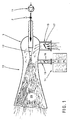
- Figure 1 shows an organ (10) for generating a high energy aerosol flow (26). It has one on one Compressed air source (11) connectable acceleration nozzle (12) and at least one connection (13) for the suction of Liquid from a liquid supply device (14). There is an upstream of the acceleration nozzle (12) Throttle valve (2) for setting the fed Amount of compressed air. There is also an organ (10) Connection (15) for intake air. Both in the connection (15) and means (16, 17) are located in the liquid supply device (14) for example in the form of swiveling throttle disks proportional setting of a predetermined ratio Air / liquid available.
- the organ (10) with the Accelerating nozzle (12) and the housing (3) is as self-priming injector for liquid and air educated.
- the housing (3) in Cross-sectional area of connection (13) like a Venturi tube narrowed and then to the free end steadily expanding. This results in the narrowest area Cross section and upstream thereof a negative pressure zone, which allows the organ (10) to automatically liquid and Suck air and the two media to an intense Disperse aerosol flow (26) homogeneously.
- FIG. 1 An exemplary arrangement is shown in FIG which several aerosol generating organs (10), in Direction of movement (4) of the profile (1) one behind the other, in one the profile (1) vertically intersecting plane on each common bracket (18), concentric against the profile (1) directed, are arranged to form a cooling system.
- an arrangement may be provided at which several in the transport direction (4) of the profile (1) provided cooling systems with formation of a cooling section (19) are arranged in series.
- the aerosol-producing ones Organs (10) formed aerosol streams (26) envelop it Profile (1) with dense aerosol clouds from directed high-energy currents blown against the profile (1) and ensure rapid cooling in this way.
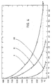
- FIG. 4 shows comparative curves of the cooling times in each case similar rolling profiles depending on different cooling media.
- the top curve I represents the Cooling process of a rolled section from an initial 900 ° C to 90 ° C within 70 minutes in still, dry air.
- the middle curve II shows the cooling behavior of a Rolled profile with an accelerated air flow of initially 900 ° C to 90 ° C within 26 minutes.
- After the lower curve III takes place using an accelerated Aerosol flow a rapid cooling of a rolled section from 900 ° C to 90 ° C in 7.5 minutes. This proves that cooling with a water / air aerosol as cooling medium a significant improvement in cooling behavior causes warm whale.
- the invention is not limited to that shown in the figures Examples limited.
- devices for Generation of aerosol of the water / air type different ways known to those skilled in the art become.
- liquid and air can be forced conveyed, dosed volumetrically and atomized.
- the Arrangement or design of cooling systems or cooling sections is depending on the operational situation of the experience of the Leave to a specialist.
- the invention is simple, effective and possible except for the economical use of air as a carrier medium Reduction of hot-rolled profiles for cooling required parts of the system and their energy requirements. To that extent the invention optimally fulfills the above task.
Landscapes
- Engineering & Computer Science (AREA)
- Mechanical Engineering (AREA)
- Chemical & Material Sciences (AREA)
- Physics & Mathematics (AREA)
- Thermal Sciences (AREA)
- Crystallography & Structural Chemistry (AREA)
- Materials Engineering (AREA)
- Metallurgy (AREA)
- Organic Chemistry (AREA)
- Heat Treatments In General, Especially Conveying And Cooling (AREA)
- Nozzles (AREA)
- Preventing Corrosion Or Incrustation Of Metals (AREA)
Description
- Fig. 1
- ein Organ zur Erzeugung einer energiereichen Aerosol-Strömung, im Schnitt,
- Fig. 2
- mehrere Aerosol erzeugende Organe in einer das Profil senkrecht schneidenden Ebene an einer gemeinsamen Halterung unter Ausbildung eines Kühlsystems; in perspektivischer Ansicht,
- Fig. 3
- mehrere in Transportrichtung des Profils unter Ausbildung einer Kühlstrecke vorgesehene Kühlsysteme, in Seitenansicht,
- Fig. 4
- vergleichendes Diagramm der Abkühlzeiten.
Claims (4)
- Vorrichtung zum Kühlen von walzwarmen Profilen durch ein Kühlluft-Kühlwasser-Aerosol, mit mindestens einem Venturi-Rohr, das von Kühiluft durchströmt ist und in dessen engsten Querschnitt eine Zuführleitung für vom Venturi-Rohr angesaugtes Kühlwasser mündet, dadurch gekennzeichnet, dass im Bereich des engsten Querschnitts des Venturi-Rohrs (10) eine in dessen Achse angeordnete, mit Druckluft beaufschlagbare Beschleunigungsdüse (12) und in Strömungsrichtung vor dem Bereich des engsten Querschnitts eine Kühiluftleitung (15) münden.
- Vorrichtung nach Anspruch 1, dadurch gekennzeichnet, dass die Beschleunigungsdüse (12) vorzugsweise ein Drosselventil (2) und die Kühlluftleitung (15) sowie die Zuführleitung (13) für Kühlwasser Mittel (16, 17) zum Einstellen eines vorgegebenen Verhältnisses von Kühlluft und Kühlwasser aufweisen.
- Vorrichtung nach Anspruch 1 oder 2, dadurch gekennzeichnet, dass mehrere Venturi-Rohre (10) in einer das Profil (1) senkrecht schneidenden Ebene an einer gemeinsamen Halterung (18), konzentrisch gegen das Profil (1) gerichtet, unter Ausbildung eines Kühlsystems angeordnet sind.
- Vorrichtung nach einem oder mehreren der Ansprüche 1 bis 3, dadurch gekennzeichnet, dass mehrere in Transportrichtung des Profils (1) vorgesehene Kühlsysteme unter Ausbildung einer Kühlstrecke (19) in Reihe angeordnet sind.
Applications Claiming Priority (2)
| Application Number | Priority Date | Filing Date | Title |
|---|---|---|---|
| DE19608965 | 1996-03-08 | ||
| DE19608965A DE19608965A1 (de) | 1996-03-08 | 1996-03-08 | Verfahren und Vorrichtung sowie Kühlmedium zum Kühlen von walzwarmen Profilen |
Publications (3)
| Publication Number | Publication Date |
|---|---|
| EP0794022A2 EP0794022A2 (de) | 1997-09-10 |
| EP0794022A3 EP0794022A3 (de) | 1998-02-04 |
| EP0794022B1 true EP0794022B1 (de) | 2001-10-17 |
Family
ID=7787593
Family Applications (1)
| Application Number | Title | Priority Date | Filing Date |
|---|---|---|---|
| EP97102738A Expired - Lifetime EP0794022B1 (de) | 1996-03-08 | 1997-02-20 | Verfahren und Vorrichtung sowie Kühlmedium zum Kühlen von walzwarmen Profilen |
Country Status (5)
| Country | Link |
|---|---|
| US (1) | US5775122A (de) |
| EP (1) | EP0794022B1 (de) |
| JP (1) | JPH105844A (de) |
| AT (1) | ATE206964T1 (de) |
| DE (2) | DE19608965A1 (de) |
Families Citing this family (7)
| Publication number | Priority date | Publication date | Assignee | Title |
|---|---|---|---|---|
| DE19757485A1 (de) * | 1997-12-23 | 1999-06-24 | Schloemann Siemag Ag | Vorrichtung zum kontrollierten Abkühlen von warmgewalzten Profilen, insbesondere Trägern, direkt aus der Walzhitze |
| SE514171C2 (sv) * | 1998-02-03 | 2001-01-15 | Ericsson Telefon Ab L M | Anordning och förfarande för luftkylning av en elektrisk anordning |
| FR2800643B1 (fr) * | 1999-11-05 | 2002-08-30 | Rhodia Chimie Sa | Dispositif de pulverisation et son application a un tunnel de traitement bactericide |
| US6328226B1 (en) | 1999-12-22 | 2001-12-11 | Visteon Global Technologies, Inc. | Nozzle assembly |
| DE10124166B8 (de) * | 2001-05-15 | 2006-12-14 | Schott Ag | Verfahren zum Kühlen von Anlagenkomponenten, die von fließfähigen Medien beaufschlagt werden |
| GB2459595B (en) * | 2007-04-26 | 2011-03-23 | Panasonic Corp | A Refrigerator with Means to Provide Mist into a Storage Compartment |
| CN105268569B (zh) * | 2015-11-11 | 2017-06-27 | 西安交通大学 | 一种气液两相环状流射流与主流气体的掺混装置 |
Family Cites Families (12)
| Publication number | Priority date | Publication date | Assignee | Title |
|---|---|---|---|---|
| GB623674A (en) * | 1947-05-09 | 1949-05-20 | Electric Furnace Co | Improvements relating to heat treatment including quenching |
| CA936076A (en) * | 1969-12-01 | 1973-10-30 | Kunioka Kazuo | Method and apparatus for cooling steel materials |
| GB1336490A (en) * | 1970-12-28 | 1973-11-07 | Nippon Kokan Kk | Method and apparatus for quenching metal stocks |
| US3997376A (en) * | 1974-06-19 | 1976-12-14 | Midland-Ross Corporation | Spray mist cooling method |
| BE837884A (fr) * | 1976-01-23 | 1976-05-14 | Centre Rech Metallurgique | Perfectionnements aux dispositifs de refroidissement des profiles metalliques |
| DE2751013C3 (de) * | 1977-11-15 | 1981-07-09 | Kleinewefers Gmbh, 4150 Krefeld | Kühleinrichtung |
| US4273744A (en) * | 1978-11-27 | 1981-06-16 | Borg-Warner Corporation | Device for automatic addition of a corrosion inhibitor to a coolant system |
| FR2444514A1 (fr) * | 1978-12-22 | 1980-07-18 | Heurtey Metallurgie | Procede et dispositif de refroidissement pour le traitement des metaux |
| FR2455255A1 (fr) * | 1979-04-23 | 1980-11-21 | Centre Rech Metallurgique | Perfectionnements aux dispositifs de refroidissement de ronds metalliques ou analogues |
| BE896219A (fr) * | 1983-03-18 | 1983-09-19 | Centre Rech Metallurgique | Perfectionnement au procede de refroidissement des profiles |
| FR2675718A1 (fr) * | 1991-04-29 | 1992-10-30 | Bertin & Cie | Procede et dispositif de refroidissement d'un profile en cours de laminage. |
| DE4430856C2 (de) * | 1994-08-31 | 1996-11-07 | Kloeckner Stahl Gmbh | Verfahren zur Reduzierung und Steuerung der Oberflächenverzunderung beim Warmwalzen von Flachprodukten, insbesondere Warmbändern |
-
1996
- 1996-03-08 DE DE19608965A patent/DE19608965A1/de not_active Withdrawn
-
1997
- 1997-02-20 AT AT97102738T patent/ATE206964T1/de not_active IP Right Cessation
- 1997-02-20 DE DE59704914T patent/DE59704914D1/de not_active Expired - Fee Related
- 1997-02-20 EP EP97102738A patent/EP0794022B1/de not_active Expired - Lifetime
- 1997-02-28 JP JP9045958A patent/JPH105844A/ja active Pending
- 1997-03-07 US US08/813,762 patent/US5775122A/en not_active Expired - Fee Related
Also Published As
| Publication number | Publication date |
|---|---|
| EP0794022A3 (de) | 1998-02-04 |
| ATE206964T1 (de) | 2001-11-15 |
| DE59704914D1 (de) | 2001-11-22 |
| EP0794022A2 (de) | 1997-09-10 |
| JPH105844A (ja) | 1998-01-13 |
| US5775122A (en) | 1998-07-07 |
| DE19608965A1 (de) | 1997-09-11 |
Similar Documents
| Publication | Publication Date | Title |
|---|---|---|
| EP0081082B1 (de) | Verfahren und Vorrichtung zur Herstellung von Wollefasern | |
| EP1585601B1 (de) | Verfahren und einspritzdüse zum durchsetzen einer gasströmung mit flüssigkeitströpfchen | |
| AT522871B1 (de) | Temperiervorrichtung für Bauteile | |
| AT522007B1 (de) | Bandschwebeanlage mit einem Düsensystem | |
| EP0794022B1 (de) | Verfahren und Vorrichtung sowie Kühlmedium zum Kühlen von walzwarmen Profilen | |
| DE102012211454A1 (de) | Verfahren und Vorrichtung zur Kühlung von Oberflächen in Gießanlagen, Walzanlagen oder sonstigen Bandprozesslinien | |
| EP0089408B1 (de) | Verfahren und Vorrichtung zur Belüftung von Trockengut in einem Tunneltrocker | |
| DE3644298C2 (de) | ||
| DE2165049B2 (de) | Verfahren und Vorrichtung zum Abschrecken | |
| DE29903255U1 (de) | Windkanal | |
| DE69611129T2 (de) | Vorrichtung zum Kühlen von Walzgut | |
| DE19804184A1 (de) | Vorrichtung zur schwebenden Führung von Bändern | |
| DE2951818A1 (de) | Verfahren zur fortlaufenden kuehlbehandlung von metallischen werkstuecken, insbesondere blechen | |
| DE69221740T2 (de) | Verfahren zum Trocknen von perforierten Ziegelsteinen und Vorrichtung zum Durchführen des Verfahrens. | |
| EP1035385B1 (de) | Verfahren zur Temperierung einer Halle und Einrichtung zur Durchführung des Verfahrens | |
| DE1073716B (de) | Verfahren und Vorrichtung zum Em leiten von Luft in einen zu belüftenden Raum | |
| AT526905B1 (de) | Durchlaufkühlvorrichtung | |
| DE3872532T2 (de) | Verfahren und luftverteilungsmittel zum zufuehren von luft in einen raumbereich. | |
| DE2341988B2 (de) | Vorrichtung zur Erzeugung eines dichten Sprühnebels (Aerosols) | |
| DE10335434A1 (de) | Lüftungskanal für eine Innenraumbelüftung | |
| EP0174589A1 (de) | Vorrichtung zum Erwärmen oder Kühlen von metallischem Gut | |
| DE1954097A1 (de) | Verfahren und Vorrichtung zum Kuehlen oder Erwaermen von in Portionsgefaessen befindlichen Nahrungsmitteln | |
| DE2551048A1 (de) | Verfahren und vorrichtung zum haerten von metallblechen | |
| DE4141626C2 (de) | Vorrichtung zur Erzeugung von Wolle, insbesondere Steinwolle, aus einer Schmelze | |
| DE2167247C2 (de) | Anordnung von Luftauslässen zum Lüften eines Raumes |
Legal Events
| Date | Code | Title | Description |
|---|---|---|---|
| PUAI | Public reference made under article 153(3) epc to a published international application that has entered the european phase |
Free format text: ORIGINAL CODE: 0009012 |
|
| 17P | Request for examination filed |
Effective date: 19970310 |
|
| AK | Designated contracting states |
Kind code of ref document: A2 Designated state(s): AT DE GB IT LU SE |
|
| PUAL | Search report despatched |
Free format text: ORIGINAL CODE: 0009013 |
|
| AK | Designated contracting states |
Kind code of ref document: A3 Designated state(s): AT DE GB IT LU SE |
|
| 17Q | First examination report despatched |
Effective date: 19990624 |
|
| RAP1 | Party data changed (applicant data changed or rights of an application transferred) |
Owner name: SMS DEMAG AG |
|
| GRAG | Despatch of communication of intention to grant |
Free format text: ORIGINAL CODE: EPIDOS AGRA |
|
| GRAG | Despatch of communication of intention to grant |
Free format text: ORIGINAL CODE: EPIDOS AGRA |
|
| GRAH | Despatch of communication of intention to grant a patent |
Free format text: ORIGINAL CODE: EPIDOS IGRA |
|
| GRAH | Despatch of communication of intention to grant a patent |
Free format text: ORIGINAL CODE: EPIDOS IGRA |
|
| GRAA | (expected) grant |
Free format text: ORIGINAL CODE: 0009210 |
|
| AK | Designated contracting states |
Kind code of ref document: B1 Designated state(s): AT DE GB IT LU SE |
|
| REF | Corresponds to: |
Ref document number: 206964 Country of ref document: AT Date of ref document: 20011115 Kind code of ref document: T |
|
| REF | Corresponds to: |
Ref document number: 59704914 Country of ref document: DE Date of ref document: 20011122 |
|
| REG | Reference to a national code |
Ref country code: GB Ref legal event code: IF02 |
|
| GBT | Gb: translation of ep patent filed (gb section 77(6)(a)/1977) |
Effective date: 20020105 |
|
| PLBE | No opposition filed within time limit |
Free format text: ORIGINAL CODE: 0009261 |
|
| STAA | Information on the status of an ep patent application or granted ep patent |
Free format text: STATUS: NO OPPOSITION FILED WITHIN TIME LIMIT |
|
| 26N | No opposition filed | ||
| PGFP | Annual fee paid to national office [announced via postgrant information from national office to epo] |
Ref country code: SE Payment date: 20060214 Year of fee payment: 10 Ref country code: DE Payment date: 20060214 Year of fee payment: 10 |
|
| PGFP | Annual fee paid to national office [announced via postgrant information from national office to epo] |
Ref country code: LU Payment date: 20060215 Year of fee payment: 10 Ref country code: AT Payment date: 20060215 Year of fee payment: 10 |
|
| PGFP | Annual fee paid to national office [announced via postgrant information from national office to epo] |
Ref country code: IT Payment date: 20060228 Year of fee payment: 10 |
|
| PG25 | Lapsed in a contracting state [announced via postgrant information from national office to epo] |
Ref country code: SE Free format text: LAPSE BECAUSE OF NON-PAYMENT OF DUE FEES Effective date: 20070221 |
|
| EUG | Se: european patent has lapsed | ||
| GBPC | Gb: european patent ceased through non-payment of renewal fee |
Effective date: 20070220 |
|
| PG25 | Lapsed in a contracting state [announced via postgrant information from national office to epo] |
Ref country code: AT Free format text: LAPSE BECAUSE OF NON-PAYMENT OF DUE FEES Effective date: 20070220 |
|
| PG25 | Lapsed in a contracting state [announced via postgrant information from national office to epo] |
Ref country code: DE Free format text: LAPSE BECAUSE OF NON-PAYMENT OF DUE FEES Effective date: 20070901 |
|
| PG25 | Lapsed in a contracting state [announced via postgrant information from national office to epo] |
Ref country code: GB Free format text: LAPSE BECAUSE OF NON-PAYMENT OF DUE FEES Effective date: 20070220 |
|
| PGFP | Annual fee paid to national office [announced via postgrant information from national office to epo] |
Ref country code: GB Payment date: 20060221 Year of fee payment: 10 |
|
| PG25 | Lapsed in a contracting state [announced via postgrant information from national office to epo] |
Ref country code: LU Free format text: LAPSE BECAUSE OF NON-PAYMENT OF DUE FEES Effective date: 20070220 |
|
| PG25 | Lapsed in a contracting state [announced via postgrant information from national office to epo] |
Ref country code: IT Free format text: LAPSE BECAUSE OF NON-PAYMENT OF DUE FEES Effective date: 20070220 |