EP0794094A2 - Circuit de déclenchement, notamment pour système de protection des occupants, à sécurité critique pour véhicules de transport de personnes - Google Patents
Circuit de déclenchement, notamment pour système de protection des occupants, à sécurité critique pour véhicules de transport de personnes Download PDFInfo
- Publication number
- EP0794094A2 EP0794094A2 EP97103404A EP97103404A EP0794094A2 EP 0794094 A2 EP0794094 A2 EP 0794094A2 EP 97103404 A EP97103404 A EP 97103404A EP 97103404 A EP97103404 A EP 97103404A EP 0794094 A2 EP0794094 A2 EP 0794094A2
- Authority
- EP
- European Patent Office
- Prior art keywords
- tripping
- switch
- circuit
- circuit according
- controllable switch
- Prior art date
- Legal status (The legal status is an assumption and is not a legal conclusion. Google has not performed a legal analysis and makes no representation as to the accuracy of the status listed.)
- Granted
Links
Images

Classifications
-
- B—PERFORMING OPERATIONS; TRANSPORTING
- B60—VEHICLES IN GENERAL
- B60R—VEHICLES, VEHICLE FITTINGS, OR VEHICLE PARTS, NOT OTHERWISE PROVIDED FOR
- B60R21/00—Arrangements or fittings on vehicles for protecting or preventing injuries to occupants or pedestrians in case of accidents or other traffic risks
- B60R21/01—Electrical circuits for triggering passive safety arrangements, e.g. airbags, safety belt tighteners, in case of vehicle accidents or impending vehicle accidents
- B60R21/017—Electrical circuits for triggering passive safety arrangements, e.g. airbags, safety belt tighteners, in case of vehicle accidents or impending vehicle accidents including arrangements for providing electric power to safety arrangements or their actuating means, e.g. to pyrotechnic fuses or electro-mechanic valves
-
- H—ELECTRICITY
- H03—ELECTRONIC CIRCUITRY
- H03K—PULSE TECHNIQUE
- H03K17/00—Electronic switching or gating, i.e. not by contact-making and –breaking
- H03K17/16—Modifications for eliminating interference voltages or currents
- H03K17/161—Modifications for eliminating interference voltages or currents in field-effect transistor switches
- H03K17/165—Modifications for eliminating interference voltages or currents in field-effect transistor switches by feedback from the output circuit to the control circuit
-
- H—ELECTRICITY
- H01—ELECTRIC ELEMENTS
- H01H—ELECTRIC SWITCHES; RELAYS; SELECTORS; EMERGENCY PROTECTIVE DEVICES
- H01H35/00—Switches operated by change of a physical condition
- H01H35/14—Switches operated by change of acceleration, e.g. by shock or vibration, inertia switch
-
- H—ELECTRICITY
- H01—ELECTRIC ELEMENTS
- H01H—ELECTRIC SWITCHES; RELAYS; SELECTORS; EMERGENCY PROTECTIVE DEVICES
- H01H9/00—Details of switching devices, not covered by groups H01H1/00 - H01H7/00
- H01H9/54—Circuit arrangements not adapted to a particular application of the switching device and for which no provision exists elsewhere
- H01H9/547—Combinations of mechanical switches and static switches, the latter being controlled by the former
Definitions
- the invention relates to a trigger circuit, in particular for safety-critical occupant protection systems for vehicles for the transportation of passengers, according to the preamble of claim 1.
- safety-critical systems in particular in safety-critical occupant protection systems that are used in vehicles for passenger transport, such as Airbag systems or belt tensioners, high system reliability is required.
- Airbag systems usually have a trigger circuit for each airbag with a triggering device that actuates the airbag, the so-called squib, which is located in series between two switches.
- a control unit interacting with accelerometers activates in the event of a dangerous one
- the trigger device impacts by closing the switches in the trigger circuit by means of a trigger signal.
- it is known to provide a mechanical safety switch in the trigger circuit which responds to accelerations and which has to switch the entire trigger current.
- safety switches of this type have to switch the entire tripping current, for example the ignition current flowing through a squib, they are complex and expensive in terms of the contact design.
- an electronic release device with an electronic accelerometer is installed centrally in the vehicle, which measures the acceleration occurring in the event of an impact.
- release devices are connected to output stages of the control unit, to which a mechanical safety switch is assigned.
- the mechanical safety switch is designed to prevent the airbags from being triggered incorrectly as a result of a fault in the electronics.
- a trigger switch can be used on the one hand in such a way that its circuit state is queried by a microprocessor of the control unit and is logically linked to the result of the acceleration measurement by the microprocessor. It is also possible to use the To provide a trigger switch as a quasi-active element in the trigger circuit, the logic connection of the trigger signal from the control device to the switching state of the trigger switch being implemented by a corresponding circuit.
- a mechanical trigger switch as a safety switch has the advantage that the trigger switch does not have to switch the entire trigger current, but it is disadvantageous in the case of a trigger switch as well as in the case of a safety switch switching the entire trigger current that bouncing can occur, as a result of which the person-protecting persons are triggered Means, so the airbags or the belt tensioner can be delayed.
- the object of the invention is to provide a further trigger circuit of the type mentioned at the outset, in which in particular the mechanical safety switch which responds to accelerations does not impair the function of the trigger circuit.
- this object is achieved in a trigger circuit of the type mentioned at the outset by the characterizing features of claim 1.
- a trigger circuit is therefore provided in the trigger circuit, which closes a controllable switch in series with the trigger device when the mechanical safety switch is first closed, i.e. controls its conductive state, and which then controls the controllable switch as a result of the trigger current and / or by means of a retriggerable timer holds conductive for at least a predetermined time.
- This self-retaining character of the controllable switch acted upon by the control circuit ensures that the tripping current is independent of this can flow freely from the subsequent switching state of the mechanical safety switch.
- the inventive design of the trigger circuit has the particular advantage that relatively simple and therefore inexpensive switches can be used as mechanical safety switches without the reliability of the safety-critical system or the trigger circuit being impaired thereby.
- a detection circuit provided in the control circuit detects not only the state of the mechanical safety switch but also the state of a switch actuated by the control unit in the trigger circuit. In this way, the reliability of the tripping circuit according to the invention can be increased further, since the controllable switch in the tripping current path is only closed when the mechanical safety switch and a switch acted upon by the control unit are closed in the tripping current path.
- the detection circuit for detecting the switch states and the tripping current flowing via the tripping device can be implemented as a voltage divider, from whose center tap a detection signal to be supplied to an output circuit of the control circuit can be taken.
- a particularly simple circuit structure is obtained if the safety switch and the controllable switch are connected in parallel to one another and are in series with the triggering device.
- This circuit has the advantage that the tripping current flows both via the mechanical safety switch and via the controllable switch located parallel to it, as soon as the mechanical safety switch remains closed after a possible bouncing. This considerably reduces the load on the controllable switch. Accordingly, a simpler and therefore less expensive switch can also be used for the controllable switch, since the controllable switch only has to carry the entire tripping current for a short time.
- a further simplification of the mechanical safety switch is possible if it is parallel to the triggering device.
- the trigger circuit has an input connection 10 to an output 11 of a voltage supply source, not shown, e.g. a power supply, and connected to one terminal of a storage capacitor 12, the other terminal of which is connected to ground.
- a voltage supply source not shown, e.g. a power supply
- a mechanical safety switch 13, a first switch 14 which can be acted upon by a microprocessor of a control device (not shown), a triggering device 15, for. B. a squib of an airbag or belt tensioner system, and a second switch 16 which can be acted upon by the microprocessor are connected in this order in series between the input connection 10 and ground.
- Parallel to the mechanical safety switch 13 is a controllable switch 17, for. B. a field effect transistor, in particular a MOS field effect transistor, preferably a self-locking MOS field effect transistor, the control input of which can be acted upon by a control circuit 19 via a line 18 with a control signal in order to control the controllable switch 17 in its conductive state.
- the control circuit 19 comprises a detection circuit 20 and an output circuit 21.
- the detection circuit 20 is formed by a series circuit comprising a diode 22 and two resistors 23, 24 connected in parallel with the triggering device 15.
- the two resistors 23, 24 form a voltage divider 25, at the center tap 26 a detection signal, which indicates a tripping current, is removed and applied to the base of a transistor 27 acting as a switch of the output circuit.
- the transistor 27 is connected to its collector-emitter path directly to the line 18, which is the control connection of the controllable switch 17, and connected via a resistor 28 to the input terminal 10 of the trigger circuit.
- the other connection of the collector-emitter path of the transistor 27 is connected to the ground connection of the trigger device 15, so that it can be connected to ground via the switch 16.
- the control unit detects a dangerous impact, the switches 14, 16, which normally keep the triggering device 15 at a floating potential, are closed, which is indicated by the arrows ⁇ P. Since significant acceleration forces act on the mechanical safety switch 13 in the event of a dangerous impact, as indicated by the arrow a, the latter closes, so that a trigger current flows from the input connection 10 via the safety switch 13, the switch 14, the trigger device 15 and the switch 16 .
- the voltage drop across the tripping device 15 as a result of the tripping current is present at the voltage divider 25, so that a voltage led to the base of the transistor 27 as a detection signal occurs at the center tap 26 and brings the collector-emitter path of the transistor 27 into its conductive state.
- the voltage applied to the control connection of the controllable switch 17 by means of the line 18 is drawn to a value which brings the controllable switch 17 into its conductive state.
- the transistor 27 can be operated as a pure switch or also as a resistive switch, in the latter case the resistor 28 and the collector-emitter path of the transistor 27 one Form voltage divider, which is designed so that the controllable switch 17 is supplied with the required control voltage.
- the trigger current flows in whole or in part via the controllable switch 17 to the triggering device 15, depending on whether the mechanical safety switch 13 is closed or opened briefly as a result of bouncing.
- controllable switch 17 Since the tripping current can flow freely in this way after the mechanical safety switch 13 has been closed for the first time, the controllable switch 17 is also kept in its conductive state by the control circuit 19.
- controllable switch 17 Due to this self-holding of the circuit of controllable switch 17 and anise control circuit 19, that is to say that the controllable switch 17 is kept conductive for as long as a tripping current flows over it, the tripping circuit according to the invention remains conductive for the tripping current regardless of the mechanical safety switch 13, even if the mechanical safety switch 13 should open briefly as a result of bouncing.
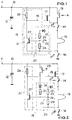
- Fig. 2 shows another trigger circuit according to the invention, in which the trigger device 15 together with two switches 14, 16 is in series between an input terminal 10 and ground.
- a controllable switch 17 is arranged between the switch 14 on the input side with respect to the triggering device 15 and the input connection, the control connection of which is connected via the line 18 to the output circuit 21 of the control circuit 19.
- a mechanical safety switch 29 is provided with a diode 30 and a resistor 31 between the input terminal 10 and the center tap 26 of the voltage divider 25 provided in the detection circuit 20 is connected in series.
- the switches 14, 16, which keep the trigger device 15 at floating potential are brought into their conductive state by a control device, as indicated by the arrows ⁇ P, and the mechanical safety switch 29 closes as a result of an acceleration acting on it, as indicated by the arrow a indicated, so initially flows from the input terminal 10 via the mechanical safety switch 29, the diode 30, the resistor 31, the resistor 24 of the voltage divider 25 and the closed switch 16, a current which is at the center tap 26 of another, consisting of resistor 31 and resistor 24 Voltage divider causes a voltage which is fed as a detection signal to the base of transistor 27.
- an output signal which brings the controllable switch 17 into its conductive state is applied to the control input thereof from the output circuit 21 of the control circuit 19 via the line 18.
- a tripping current can flow via the tripping device 19, which is detected by means of the voltage divider 25 and by which, as in the exemplary embodiment according to FIG. 1, the controllable switch 17 is held in its conductive state.
- controllable switch 17 arranged in the tripping current path is kept conductive as long as a tripping current flows.
- FIG. 3 shows a third trigger circuit which largely corresponds to the trigger circuit explained with reference to FIG. 2.
- the third trigger circuit has a retriggerable timing element 32, the input connection of which is connected to the connection point between the diode 30 and the resistor 31 and the output of which is applied to an input of a NOR element 33.
- the output of the NOR gate 33 is connected to the line 18 serving as the control connection of the controllable switch 17.
- the connection of the collector-emitter path of the transistor 27, which is connected via the resistor 28 to the input terminal 10 of the trigger circuit, is connected to the other input of the NOR gate 33, which is negated.
- the timer 32 shown in Fig. 3 is designed so that it forwards an applied positive input pulse and is driven by the negative edge of an input pulse so that its output after a drop in the input pulse for a predetermined time, for. B. 10 ms, is kept at a positive level corresponding to the positive input pulse (logical one).
- the input of the timing element 32 is supplied with a positive voltage from the connection point between the diode 30 and the resistor 31, which is present as a logic one at the other input of the NOR element 33. Because of each of the two input signals, a logic zero signal is present at the output of the NOR gate 33, which controls the controllable switch 17, which is designed, for example, as a p-channel field effect transistor, into its conductive state.
- controllable switch 17 is thus controlled into its conductive state at least for the time specified by the timing element 32.
- controllable switch 17 After the controllable switch 17 is in the conductive state and a tripping current flows, the controllable switch 17 is kept in its conductive state due to the tripping current.
- controllable switch 17 arranged in the tripping current path is kept conductive as long as the output of the timing element is high and / or a tripping current flows via the tripping device 19.
- the retriggerable timer 32 described with reference to FIG. 3 can also be used in a corresponding manner in a trigger circuit, as was described with reference to FIG. 1.
- the input of the timing element 32 would then have to be connected to the connection point between the diode 22 and the resistor 23 of the voltage divider 25.
- controllable switch 17 in its conductive state only with the retriggerable timing element 32, which detects the current via the mechanical safety switch, regardless of the tripping current.
- the present invention makes it possible, irrespective of the bounce behavior of mechanical switches, to provide a mechanical switch either as a safety switch in series (FIG. 1) or as a trigger switch in parallel (FIGS. 2 and 3) with the triggering device 15.
- Mechanical safety switches can therefore be arranged according to the invention directly in the trigger circuit, which enables reliable mechanical monitoring of the control unit and can reliably rule out incorrect triggering as a result of a faulty microprocessor in the control unit or accelerometer.
- Another advantage of this invention is that either - as shown in Figure 1 - the parallel connection of mechanical safety switch 13 and controllable switch 17 or - as shown in Figure 2 - the controllable switch 17 solely the function of the input side with respect to the trigger device 15 Switch 14 can take over.
- the switch 14 on the input side with respect to the trigger device 15 becomes superfluous and can be omitted without the potential-free arrangement of the trigger device being impaired.
Landscapes
- Engineering & Computer Science (AREA)
- Mechanical Engineering (AREA)
- Air Bags (AREA)
- Keying Circuit Devices (AREA)
Applications Claiming Priority (2)
| Application Number | Priority Date | Filing Date | Title |
|---|---|---|---|
| DE19608393 | 1996-03-05 | ||
| DE19608393A DE19608393A1 (de) | 1996-03-05 | 1996-03-05 | Auslöseschaltkreis, insbesondere für ein sicherheitskritisches Insassenschutzsystem für Fahrzeuge zur Personenbeförderung |
Publications (3)
| Publication Number | Publication Date |
|---|---|
| EP0794094A2 true EP0794094A2 (fr) | 1997-09-10 |
| EP0794094A3 EP0794094A3 (fr) | 1997-12-10 |
| EP0794094B1 EP0794094B1 (fr) | 2001-07-18 |
Family
ID=7787231
Family Applications (1)
| Application Number | Title | Priority Date | Filing Date |
|---|---|---|---|
| EP97103404A Expired - Lifetime EP0794094B1 (fr) | 1996-03-05 | 1997-03-01 | Circuit de déclenchement, notamment pour système de protection des occupants, à sécurité critique pour véhicules de transport de personnes |
Country Status (3)
| Country | Link |
|---|---|
| EP (1) | EP0794094B1 (fr) |
| DE (2) | DE19608393A1 (fr) |
| ES (1) | ES2161389T3 (fr) |
Cited By (3)
| Publication number | Priority date | Publication date | Assignee | Title |
|---|---|---|---|---|
| EP0997349A1 (fr) * | 1998-10-27 | 2000-05-03 | Siemens Aktiengesellschaft | Dispositif de mise à feu du détonateur d'un système de retenue d'un véhicule |
| US6365987B2 (en) | 1998-06-25 | 2002-04-02 | Siemens Aktiengesellschaft | Device for triggering and method for operating an occupant protection device of a motor vehicle using a testable acceleration switch |
| WO2010049194A1 (fr) * | 2008-10-28 | 2010-05-06 | Robert Bosch Gmbh | Dispositif d'alimentation d'un étage final d'allumage |
Families Citing this family (5)
| Publication number | Priority date | Publication date | Assignee | Title |
|---|---|---|---|---|
| DE19842083A1 (de) * | 1998-03-07 | 1999-09-09 | Telefunken Microelectron | Verfahren zum Betrieb einer Insassensicherheitseinrichtung sowie Ansteuereinheit |
| DE19826704C1 (de) * | 1998-06-16 | 2000-02-10 | Siemens Ag | Vorrichtung zum Zünden eines Zündelements eines Kraftfahrzeug-Insassenschutzmittels |
| DE19918634A1 (de) * | 1999-04-23 | 2000-11-02 | Siemens Ag | Elektrische Zündschaltung für ein Kraftfahrzeug-Insassenschutzsystem, und entsprechend ausgelegtes Kraftfahrzeug-Insassenschutzsystem |
| EP1051312B1 (fr) | 1998-12-01 | 2003-11-12 | Siemens Aktiengesellschaft | Circuit d'amorcage electrique pour systeme de protection de passager d'un vehicule |
| DE102005008905A1 (de) * | 2005-02-26 | 2006-08-31 | Conti Temic Microelectronic Gmbh | Ansteuerschaltung für eine durch zumindest einen Gleichspannungsimpuls auslösbare Zündeinheit einer Insassenschutzeinrichtung |
Family Cites Families (11)
| Publication number | Priority date | Publication date | Assignee | Title |
|---|---|---|---|---|
| DE3608525A1 (de) * | 1986-03-14 | 1987-09-17 | Audi Ag | Verfahren zur ueberpruefung eines kraftfahrzeugsicherheitssystems |
| DE3621589A1 (de) * | 1986-06-27 | 1988-01-07 | Audi Ag | Schaltung zur spannungsversorgung eines elektrischen bausteines |
| JPH04500641A (ja) * | 1988-09-14 | 1992-02-06 | ローベルト・ボッシュ・ゲゼルシャフト・ミット・ベシュレンクテル・ハフツング | 自動車の搭乗者を保護するエアバッグ装置 |
| JP2654576B2 (ja) * | 1991-04-02 | 1997-09-17 | 株式会社デンソー | 車両用乗員保護システムのための起動装置 |
| GB2259616B (en) * | 1991-07-25 | 1995-07-05 | Autoliv Dev | Improvements in or relating to an ignition circuit for an air-bag |
| JPH05170045A (ja) * | 1991-12-24 | 1993-07-09 | Mitsubishi Electric Corp | 車両用乗員保護装置の起動装置 |
| DE4306488A1 (de) * | 1993-03-02 | 1994-09-08 | Autoliv Dev | Auslösesystem für Airbags |
| JP2853511B2 (ja) * | 1993-04-27 | 1999-02-03 | 三菱電機株式会社 | 乗員保護装置の故障診断装置 |
| JPH0781515A (ja) * | 1993-09-14 | 1995-03-28 | Nippondenso Co Ltd | 車両用乗員保護装置 |
| JP3219119B2 (ja) * | 1994-04-21 | 2001-10-15 | 株式会社デンソー | 乗員保護装置における起動装置 |
| DE4424020A1 (de) * | 1994-07-08 | 1996-01-11 | Telefunken Microelectron | Prüfverfahren für eine passive Sicherheitseinrichtung in Kraftfahrzeugen |
-
1996
- 1996-03-05 DE DE19608393A patent/DE19608393A1/de not_active Withdrawn
-
1997
- 1997-03-01 ES ES97103404T patent/ES2161389T3/es not_active Expired - Lifetime
- 1997-03-01 DE DE59704051T patent/DE59704051D1/de not_active Expired - Fee Related
- 1997-03-01 EP EP97103404A patent/EP0794094B1/fr not_active Expired - Lifetime
Cited By (5)
| Publication number | Priority date | Publication date | Assignee | Title |
|---|---|---|---|---|
| US6365987B2 (en) | 1998-06-25 | 2002-04-02 | Siemens Aktiengesellschaft | Device for triggering and method for operating an occupant protection device of a motor vehicle using a testable acceleration switch |
| EP0997349A1 (fr) * | 1998-10-27 | 2000-05-03 | Siemens Aktiengesellschaft | Dispositif de mise à feu du détonateur d'un système de retenue d'un véhicule |
| WO2010049194A1 (fr) * | 2008-10-28 | 2010-05-06 | Robert Bosch Gmbh | Dispositif d'alimentation d'un étage final d'allumage |
| CN102196948B (zh) * | 2008-10-28 | 2013-10-23 | 罗伯特·博世有限公司 | 用于点火输出级的供电的装置 |
| US8817450B2 (en) | 2008-10-28 | 2014-08-26 | Robert Bosch Gmbh | Device for energizing an ignition output stage |
Also Published As
| Publication number | Publication date |
|---|---|
| EP0794094A3 (fr) | 1997-12-10 |
| DE19608393A1 (de) | 1997-09-11 |
| DE59704051D1 (de) | 2001-08-23 |
| ES2161389T3 (es) | 2001-12-01 |
| EP0794094B1 (fr) | 2001-07-18 |
Similar Documents
| Publication | Publication Date | Title |
|---|---|---|
| EP0284770B2 (fr) | Circuit de commande pour dispositif de protection | |
| DE102010043882B4 (de) | Getakteter Sicherheitsschalter | |
| DE3439310C2 (fr) | ||
| DE4432444C2 (de) | Fahrzeuginsassen-Schutzsystem | |
| DE3506487C2 (de) | Spannungsversorgungseinrichtung für eine Insassenschutzvorrichtung in einem Fahrzeug | |
| DE19505334C2 (de) | Elektronisches Gerät | |
| EP2807057B1 (fr) | Procédé et dispositif pour détecter une disponibilité opérationnelle d'un dispositif de commande | |
| EP0022146B1 (fr) | Circuit pour enregistrer le déclenchement erroné d'au moins une installation de sécurité servant à la protection des occupants d'un véhicule lors d'un accident | |
| DE112017001822T5 (de) | Überstrom-schutzschaltung | |
| EP0167792A1 (fr) | Circuit de détection de signaux de déclenchement erronés pour un système de retenue | |
| DE19547307B4 (de) | Passagierschutzvorrichtung und zugehörige Betätigungsvorrichtung | |
| WO1992017358A1 (fr) | Circuit pour regulateur | |
| DE10255115B3 (de) | Ansteuerschaltung für eine Zündpille eines Fahrzeugrückhaltesystems | |
| DE4224477B4 (de) | Sicherheitsanordnung in einer Zündschaltung für einen Airbag | |
| EP0794094B1 (fr) | Circuit de déclenchement, notamment pour système de protection des occupants, à sécurité critique pour véhicules de transport de personnes | |
| DE4137611A1 (de) | Richtungs- und warnblinkanlage fuer ein fahrzeug, insbesondere fuer ein kraftfahrzeug | |
| WO2018108514A1 (fr) | Véhicule automobile à moteur électrique, notamment véhicule hybride ou électrique | |
| WO2018001665A1 (fr) | Dispositif de commande multi-tension pour véhicule automobile, véhicule automobile et procédé de fonctionnement du dispositif de commande | |
| DE19617250C1 (de) | Schaltungsanordnung zum Verhindern von Fehlauslösungen von Insassenschutzsystemen | |
| EP1051312A1 (fr) | Circuit d'amor age electrique pour systeme de protection de passager d'un vehicule | |
| DE3627239A1 (de) | Schaltung zur ansteuerung und ueberwachung von zuendkreisen | |
| DE10322506A1 (de) | Stromversorgungsgerät für ein Kraftfahrzeug | |
| DE3920693A1 (de) | Ausloesekreis-ueberwachungsschaltung, insbesondere in fahrzeuginsassen-sicherheitssystemen | |
| EP1319265B1 (fr) | Circuit de protection | |
| DE10211099B4 (de) | Vorrichtung zur Ansteuerung einer elektrischen Last |
Legal Events
| Date | Code | Title | Description |
|---|---|---|---|
| PUAI | Public reference made under article 153(3) epc to a published international application that has entered the european phase |
Free format text: ORIGINAL CODE: 0009012 |
|
| AK | Designated contracting states |
Kind code of ref document: A2 Designated state(s): DE ES FR GB IT SE |
|
| PUAL | Search report despatched |
Free format text: ORIGINAL CODE: 0009013 |
|
| AK | Designated contracting states |
Kind code of ref document: A3 Designated state(s): DE ES FR GB IT SE |
|
| 17P | Request for examination filed |
Effective date: 19980226 |
|
| 17Q | First examination report despatched |
Effective date: 19990914 |
|
| RAP1 | Party data changed (applicant data changed or rights of an application transferred) |
Owner name: TEMIC TELEFUNKEN MICROELECTRONIC GMBH |
|
| GRAG | Despatch of communication of intention to grant |
Free format text: ORIGINAL CODE: EPIDOS AGRA |
|
| GRAG | Despatch of communication of intention to grant |
Free format text: ORIGINAL CODE: EPIDOS AGRA |
|
| GRAH | Despatch of communication of intention to grant a patent |
Free format text: ORIGINAL CODE: EPIDOS IGRA |
|
| GRAH | Despatch of communication of intention to grant a patent |
Free format text: ORIGINAL CODE: EPIDOS IGRA |
|
| ITF | It: translation for a ep patent filed | ||
| GRAA | (expected) grant |
Free format text: ORIGINAL CODE: 0009210 |
|
| AK | Designated contracting states |
Kind code of ref document: B1 Designated state(s): DE ES FR GB IT SE |
|
| REF | Corresponds to: |
Ref document number: 59704051 Country of ref document: DE Date of ref document: 20010823 |
|
| GBT | Gb: translation of ep patent filed (gb section 77(6)(a)/1977) |
Effective date: 20010925 |
|
| RAP2 | Party data changed (patent owner data changed or rights of a patent transferred) |
Owner name: CONTI TEMIC MICROELECTRONIC GMBH |
|
| REG | Reference to a national code |
Ref country code: ES Ref legal event code: FG2A Ref document number: 2161389 Country of ref document: ES Kind code of ref document: T3 |
|
| ET | Fr: translation filed | ||
| REG | Reference to a national code |
Ref country code: GB Ref legal event code: IF02 |
|
| PLBE | No opposition filed within time limit |
Free format text: ORIGINAL CODE: 0009261 |
|
| STAA | Information on the status of an ep patent application or granted ep patent |
Free format text: STATUS: NO OPPOSITION FILED WITHIN TIME LIMIT |
|
| 26N | No opposition filed | ||
| PGFP | Annual fee paid to national office [announced via postgrant information from national office to epo] |
Ref country code: IT Payment date: 20070625 Year of fee payment: 11 |
|
| PGFP | Annual fee paid to national office [announced via postgrant information from national office to epo] |
Ref country code: ES Payment date: 20090324 Year of fee payment: 13 |
|
| PGFP | Annual fee paid to national office [announced via postgrant information from national office to epo] |
Ref country code: GB Payment date: 20090325 Year of fee payment: 13 |
|
| PG25 | Lapsed in a contracting state [announced via postgrant information from national office to epo] |
Ref country code: IT Free format text: LAPSE BECAUSE OF NON-PAYMENT OF DUE FEES Effective date: 20080301 |
|
| PGFP | Annual fee paid to national office [announced via postgrant information from national office to epo] |
Ref country code: SE Payment date: 20090312 Year of fee payment: 13 Ref country code: DE Payment date: 20090320 Year of fee payment: 13 |
|
| PGFP | Annual fee paid to national office [announced via postgrant information from national office to epo] |
Ref country code: FR Payment date: 20090312 Year of fee payment: 13 |
|
| EUG | Se: european patent has lapsed | ||
| GBPC | Gb: european patent ceased through non-payment of renewal fee |
Effective date: 20100301 |
|
| REG | Reference to a national code |
Ref country code: FR Ref legal event code: ST Effective date: 20101130 |
|
| PG25 | Lapsed in a contracting state [announced via postgrant information from national office to epo] |
Ref country code: FR Free format text: LAPSE BECAUSE OF NON-PAYMENT OF DUE FEES Effective date: 20100331 |
|
| PG25 | Lapsed in a contracting state [announced via postgrant information from national office to epo] |
Ref country code: DE Free format text: LAPSE BECAUSE OF NON-PAYMENT OF DUE FEES Effective date: 20101001 |
|
| PG25 | Lapsed in a contracting state [announced via postgrant information from national office to epo] |
Ref country code: GB Free format text: LAPSE BECAUSE OF NON-PAYMENT OF DUE FEES Effective date: 20100301 |
|
| REG | Reference to a national code |
Ref country code: ES Ref legal event code: FD2A Effective date: 20110419 |
|
| PG25 | Lapsed in a contracting state [announced via postgrant information from national office to epo] |
Ref country code: ES Free format text: LAPSE BECAUSE OF NON-PAYMENT OF DUE FEES Effective date: 20110404 |
|
| PG25 | Lapsed in a contracting state [announced via postgrant information from national office to epo] |
Ref country code: ES Free format text: LAPSE BECAUSE OF NON-PAYMENT OF DUE FEES Effective date: 20100302 |
|
| PG25 | Lapsed in a contracting state [announced via postgrant information from national office to epo] |
Ref country code: SE Free format text: LAPSE BECAUSE OF NON-PAYMENT OF DUE FEES Effective date: 20100302 |