EP0794100A2 - Procédé pour améliorer le confort de conduite notamment pour véhicules ferroviaires - Google Patents
Procédé pour améliorer le confort de conduite notamment pour véhicules ferroviaires Download PDFInfo
- Publication number
- EP0794100A2 EP0794100A2 EP97103069A EP97103069A EP0794100A2 EP 0794100 A2 EP0794100 A2 EP 0794100A2 EP 97103069 A EP97103069 A EP 97103069A EP 97103069 A EP97103069 A EP 97103069A EP 0794100 A2 EP0794100 A2 EP 0794100A2
- Authority
- EP
- European Patent Office
- Prior art keywords
- spring
- characteristic
- additional
- chassis frame
- soft
- Prior art date
- Legal status (The legal status is an assumption and is not a legal conclusion. Google has not performed a legal analysis and makes no representation as to the accuracy of the status listed.)
- Granted
Links
Images



Classifications
-
- B—PERFORMING OPERATIONS; TRANSPORTING
- B60—VEHICLES IN GENERAL
- B60G—VEHICLE SUSPENSION ARRANGEMENTS
- B60G11/00—Resilient suspensions characterised by arrangement, location or kind of springs
- B60G11/32—Resilient suspensions characterised by arrangement, location or kind of springs having springs of different kinds
- B60G11/48—Resilient suspensions characterised by arrangement, location or kind of springs having springs of different kinds not including leaf springs
-
- B—PERFORMING OPERATIONS; TRANSPORTING
- B60—VEHICLES IN GENERAL
- B60G—VEHICLE SUSPENSION ARRANGEMENTS
- B60G11/00—Resilient suspensions characterised by arrangement, location or kind of springs
- B60G11/32—Resilient suspensions characterised by arrangement, location or kind of springs having springs of different kinds
- B60G11/48—Resilient suspensions characterised by arrangement, location or kind of springs having springs of different kinds not including leaf springs
- B60G11/56—Resilient suspensions characterised by arrangement, location or kind of springs having springs of different kinds not including leaf springs having helical, spiral or coil springs, and also fluid springs
- B60G11/58—Resilient suspensions characterised by arrangement, location or kind of springs having springs of different kinds not including leaf springs having helical, spiral or coil springs, and also fluid springs arranged coaxially
-
- B—PERFORMING OPERATIONS; TRANSPORTING
- B60—VEHICLES IN GENERAL
- B60G—VEHICLE SUSPENSION ARRANGEMENTS
- B60G17/00—Resilient suspensions having means for adjusting the spring or vibration-damper characteristics, for regulating the distance between a supporting surface and a sprung part of vehicle or for locking suspension during use to meet varying vehicular or surface conditions, e.g. due to speed or load
- B60G17/02—Spring characteristics, e.g. mechanical springs and mechanical adjusting means
- B60G17/027—Mechanical springs regulated by fluid means
- B60G17/0272—Mechanical springs regulated by fluid means the mechanical spring being a coil spring
-
- B—PERFORMING OPERATIONS; TRANSPORTING
- B61—RAILWAYS
- B61F—RAIL VEHICLE SUSPENSIONS, e.g. UNDERFRAMES, BOGIES OR ARRANGEMENTS OF WHEEL AXLES; RAIL VEHICLES FOR USE ON TRACKS OF DIFFERENT WIDTH; PREVENTING DERAILING OF RAIL VEHICLES; WHEEL GUARDS, OBSTRUCTION REMOVERS OR THE LIKE FOR RAIL VEHICLES
- B61F5/00—Constructional details of bogies; Connections between bogies and vehicle underframes; Arrangements or devices for adjusting or allowing self-adjustment of wheel axles or bogies when rounding curves
- B61F5/26—Mounting or securing axle-boxes in vehicle or bogie underframes
- B61F5/30—Axle-boxes mounted for movement under spring control in vehicle or bogie underframes
- B61F5/301—Axle-boxes mounted for movement under spring control in vehicle or bogie underframes incorporating metal springs
-
- F—MECHANICAL ENGINEERING; LIGHTING; HEATING; WEAPONS; BLASTING
- F16—ENGINEERING ELEMENTS AND UNITS; GENERAL MEASURES FOR PRODUCING AND MAINTAINING EFFECTIVE FUNCTIONING OF MACHINES OR INSTALLATIONS; THERMAL INSULATION IN GENERAL
- F16F—SPRINGS; SHOCK-ABSORBERS; MEANS FOR DAMPING VIBRATION
- F16F13/00—Units comprising springs of the non-fluid type as well as vibration-dampers, shock-absorbers, or fluid springs
- F16F13/002—Units comprising springs of the non-fluid type as well as vibration-dampers, shock-absorbers, or fluid springs comprising at least one fluid spring
-
- B—PERFORMING OPERATIONS; TRANSPORTING
- B60—VEHICLES IN GENERAL
- B60G—VEHICLE SUSPENSION ARRANGEMENTS
- B60G2202/00—Indexing codes relating to the type of spring, damper or actuator
- B60G2202/10—Type of spring
- B60G2202/12—Wound spring
-
- B—PERFORMING OPERATIONS; TRANSPORTING
- B60—VEHICLES IN GENERAL
- B60G—VEHICLE SUSPENSION ARRANGEMENTS
- B60G2202/00—Indexing codes relating to the type of spring, damper or actuator
- B60G2202/10—Type of spring
- B60G2202/14—Plastic spring, e.g. rubber
-
- B—PERFORMING OPERATIONS; TRANSPORTING
- B60—VEHICLES IN GENERAL
- B60G—VEHICLE SUSPENSION ARRANGEMENTS
- B60G2202/00—Indexing codes relating to the type of spring, damper or actuator
- B60G2202/10—Type of spring
- B60G2202/15—Fluid spring
- B60G2202/152—Pneumatic spring
-
- B—PERFORMING OPERATIONS; TRANSPORTING
- B60—VEHICLES IN GENERAL
- B60G—VEHICLE SUSPENSION ARRANGEMENTS
- B60G2300/00—Indexing codes relating to the type of vehicle
- B60G2300/10—Railway vehicles
-
- B—PERFORMING OPERATIONS; TRANSPORTING
- B60—VEHICLES IN GENERAL
- B60G—VEHICLE SUSPENSION ARRANGEMENTS
- B60G2400/00—Indexing codes relating to detected, measured or calculated conditions or factors
- B60G2400/60—Load
-
- B—PERFORMING OPERATIONS; TRANSPORTING
- B60—VEHICLES IN GENERAL
- B60G—VEHICLE SUSPENSION ARRANGEMENTS
- B60G2500/00—Indexing codes relating to the regulated action or device
- B60G2500/20—Spring action or springs
Definitions
- the invention relates to a method for improving driving comfort, in particular for rail vehicles, the design of the suspension connected between wheel sets and undercarriage frames of undercarriages.
- the proposed method is intended on the one hand to adhere to the predetermined, small, permissible so-called static deflections of the spring stage, referred to as primary suspension, between the loading states 'vehicle empty' and 'vehicle loading' and, on the other hand, to allow the largest possible dynamic travel when driving over rail position errors in any loading state. ie react as a very soft suspension to vertical suggestions from the rail running surface.
- Such a suspension is able to transmit vertical displacements transmitted from the track to the wheels of the undercarriage as very small forces to the mass of the undercarriage frame.
- the secondary suspension is designed to be soft in high-quality vehicles. So far, soft suspensions have not been used for primary suspension. Soft primary suspensions have not been considered necessary. Because of the unavoidable long travel path and because the roll movements stabilize strongly, soft primary suspension systems are even considered harmful and are therefore avoided.
- Hard primary suspensions between the wheel sets and chassis frame have the effect that the masses of wheel sets are coupled relatively rigidly to the mass of the chassis frame.
- the wheels can only avoid vertical bumps in the rails if they simultaneously set the mass of the wheelset and, to a lesser extent, the mass of the undercarriage frame in motion. The faster the movements, the greater the forces that occur.
- the forces transmitted by the primary springs are noticeable as action forces from the wheelset to the chassis frame.
- Large primary spring forces generate large accelerations of the chassis frame, which ultimately penetrate through the secondary suspension to the comfort of the car body.
- the same primary spring forces act in the opposite direction as reaction forces from the primary suspension into the wheel set and can be found in the wheel / rail contacts of the wheels or in the track superstructure.
- the spring level between the wheelset and chassis frame is designed so that there is a very soft suspension with a very flat spring characteristic in all loading conditions.
- the large spring travel that occurs between the different load conditions is compensated for by a suitable level compensation.
- the characteristic curve of the spring which is very flat in the narrow operating range of the spring, changes into an extremely steep curve immediately after the operating range is exceeded. Thereby the result is that if the leveling fails, the suspension becomes very hard, but the inevitable travel remains small.
- the invention has for its object to find a spring characteristic that has a consistently flat spring characteristic in all loading conditions, without large spring travel is necessary.
- the spring characteristic is ideally designed for the loading condition 'vehicle empty'. All additional loads between the loading conditions 'vehicle empty' and 'vehicle loading' are absorbed by an additional suspension, which almost or completely compensates for the otherwise required travel and does not increase the spring characteristic (spring stiffness) of the entire spring arrangement or only increases it insignificantly.
- the additional suspension and the compensation of the deflection can be done pneumatically, hydraulically or also mechanically or electromechanically.
- the spring characteristic curve increases very steeply after the operating range has been exceeded so that failures of the selected device do not lead to undesirable and only permitted large deflections.
- the advances which can be achieved with the invention consist, in particular, in the fact that the dynamic spring forces which arise when driving over an obstacle bleach very little in all loading conditions in the operating range. As a result, a shock originating from the unevenness of the road is absorbed as best as possible. The mass of the truss frame only reacts to this with a relatively small impact acceleration. If the level control fails, shocks in the chassis frame cannot prevent large accelerations. However, the spring travel, which would otherwise be activated with a continuously soft suspension with a flat spring characteristic, remains within narrow permissible limits due to the steep increase in the spring characteristics.
- the proposed spring characteristic can be realized with various constructive designs.
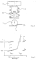
- Fig. 1 shows the theoretical replacement model of a wheel 1, which is sprung against the chassis frame 3 by means of the primary spring 2. If the wheel 1 rolls on the rail 4 over an obstacle of height h, it is raised by the amount h. The spring 2 is pressed in at its base point by the same amount h, which increases the spring force by the dynamic spring force F dyn .
- the dynamic spring force F dyn acts at the base of the spring 2 from top to bottom on the wheel 1. At the upper end of the spring 2, the same force F dyn acts in the opposite direction from the spring 2 on the chassis frame 3 as a reaction force.
- chassis frame 3 It sets the chassis frame 3 in motion with an acceleration, the size of which is directly proportional to the size of the dynamic spring force F dyn and vice versa to the size of the mass of the chassis frame 3. If the mass of the undercarriage frame 3 is constant, the impact acceleration of the undercarriage frame 3, which follows from an unevenness of the track 4, can be influenced directly by the spring 2.
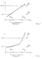
- FIG. 2 shows a spring with a linear spring characteristic which deflects between the loading states 'empty' and 'loaded' around the spring travel f.
- Fig. 4 shows schematically a primary spring arrangement, which consists of an empty load spring 5 and an additional spring 6 arranged parallel thereto.
- the empty load spring 5 alone transfers the force from the chassis frame 3 to the wheel 1.
- the auxiliary spring 6 is more or less involved in the power transmission by a regulating device 7, depending on how the distance between the chassis frame during loading or unloading 3 and bike 1 changes.
- FIG. 5 shows the spring diagram belonging to the arrangement according to FIG. 4.
- the spring characteristic 8 of the soft no-load spring 5 guarantees low dynamic spring forces F dyn in response to a rail unevenness of height h.
- the soft no-load spring 5 alone would require extremely large spring travel f between the 'empty' and 'loaded' states.
- the additional spring 6 absorbs the spring force F Lad , which corresponds exactly to the load from the additional load.
- the spring characteristic, ie the slope of the spring characteristic 9 of the no-load spring 5 plus the additional spring 6 remains almost unchanged. Regardless of the respective load, low dynamic spring forces F dyn can be achieved with such a suspension.
- the disadvantage is that the spring travel f becomes very large if the regulating device 7 fails.
- the no-load spring 5 is designed as a progressive coil spring 10 with a different diameter of the spring wire and the additional spring 6 is designed as an air bellows spring 11.
- the springs 10 and 11 are connected in parallel; the air pressure of the additional spring 11 is controlled by the approach of the chassis frame 3 to the wheel 1.
- FIG. 7 The expected effect of an extremely progressive no-load spring 10 is shown in FIG. 7 .
- the no-load spring 10 alone is effective in the work area with a very flat spring characteristic. Additional forces from the loading takes the additional spring 11.
- the common spring characteristic remains soft.
- the dynamic spring forces F dyn in response to a rail unevenness of height h are very low due to the soft spring characteristic. If the additional spring 11 fails, the load is borne solely by the no-load spring 10 in the area with an extremely steep spring characteristic. Although this leads to large dynamic spring forces F dyn ' , it keeps the permissible spring travel f within tolerable limits.
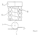
- the no-load spring 5 is designed here as a rubber coil spring 12 with a progressive coil spring as the basic element.
- the effect of the additional spring 6 is achieved by using the interior 13 of the rubber coil spring 12 as a pressure container.
- the pressure can be built up pneumatically or hydraulically.
- the no-load spring 5 is designed as a rubber roller spring 14.
- the interior 15 of the rubber roller spring 14 is pressurized.
Landscapes
- Engineering & Computer Science (AREA)
- Mechanical Engineering (AREA)
- General Engineering & Computer Science (AREA)
- Vehicle Body Suspensions (AREA)
- Springs (AREA)
- Platform Screen Doors And Railroad Systems (AREA)
Applications Claiming Priority (2)
| Application Number | Priority Date | Filing Date | Title |
|---|---|---|---|
| DE19608617 | 1996-03-06 | ||
| DE19608617A DE19608617A1 (de) | 1996-03-06 | 1996-03-06 | Verfahren zur Verbesserung des Fahrkomforts |
Publications (3)
| Publication Number | Publication Date |
|---|---|
| EP0794100A2 true EP0794100A2 (fr) | 1997-09-10 |
| EP0794100A3 EP0794100A3 (fr) | 1998-12-30 |
| EP0794100B1 EP0794100B1 (fr) | 2003-04-09 |
Family
ID=7787367
Family Applications (1)
| Application Number | Title | Priority Date | Filing Date |
|---|---|---|---|
| EP97103069A Expired - Lifetime EP0794100B1 (fr) | 1996-03-06 | 1997-02-26 | Suspension destinée à améliorer le confort de conduite, notamment pour les véhicules ferroviaires |
Country Status (4)
| Country | Link |
|---|---|
| EP (1) | EP0794100B1 (fr) |
| AT (1) | ATE236817T1 (fr) |
| DE (2) | DE19608617A1 (fr) |
| ES (1) | ES2196205T3 (fr) |
Cited By (4)
| Publication number | Priority date | Publication date | Assignee | Title |
|---|---|---|---|---|
| EP0855327A3 (fr) * | 1997-01-28 | 2000-03-29 | ContiTech Formteile GmbH | Dispositif de suspension pour un véhicule ferroviaire |
| EP1241377A3 (fr) * | 2001-03-15 | 2003-05-07 | Man Nutzfahrzeuge Ag | Procédé pour optimiser le support d'une machine |
| EP1577125A3 (fr) * | 2004-03-19 | 2006-12-06 | Audi Ag | Système de ressorts possédant une caractéristique de ressort variable pour un véhicule avec au moins un élément de ressort principal et au moins un élément d'amortissement |
| EP2199121A1 (fr) * | 2008-12-17 | 2010-06-23 | Audi AG | Suspension de roue pour véhicules automobiles |
Families Citing this family (1)
| Publication number | Priority date | Publication date | Assignee | Title |
|---|---|---|---|---|
| JP7323585B2 (ja) | 2021-09-29 | 2023-08-08 | 本田技研工業株式会社 | 推定装置、車両及び推定方法 |
Family Cites Families (13)
| Publication number | Priority date | Publication date | Assignee | Title |
|---|---|---|---|---|
| DE959250C (de) * | 1942-07-25 | 1957-02-28 | Phaenomen Werke Gustav Hiller | Fahrzeugfederung |
| DE2336782C2 (de) * | 1973-07-19 | 1987-05-27 | Clouth Gummiwerke AG, 5000 Köln | Federvorrichtung |
| DE8025791U1 (de) * | 1980-09-26 | 1993-04-22 | Knaus, Hans A.J., 7800 Freiburg | Zusatzfeder, insbesondere für Kraftfahrzeuge |
| DE3174727D1 (en) * | 1980-11-25 | 1986-07-03 | Bayerische Motoren Werke Ag | Suspension system for vehicles |
| CH652669A5 (de) * | 1981-11-09 | 1985-11-29 | Inventio Ag | Wagenkastenabstuetzung mit einstellbarer querfederung fuer drehgestell-schienenfahrzeuge. |
| US4488495A (en) * | 1981-12-28 | 1984-12-18 | The Budd Company | Soft primar suspension system for a railway car |
| DE3228603A1 (de) * | 1982-07-30 | 1984-02-02 | Knorr-Bremse GmbH, 8000 München | Federung fuer fahrzeugraeder |
| DE3421678C2 (de) * | 1984-06-09 | 1986-08-14 | Wilhelm Bläser GmbH & Co KG, 4618 Kamen | Schienenfahrzeug, insbesondere Bodenentleerer |
| HU208367B (en) * | 1986-04-29 | 1993-09-28 | Lajos Laib | Springy unit for vehicles |
| DE3704492A1 (de) * | 1987-02-13 | 1988-08-25 | Talbot Waggonfab | Laufwerkfederung fuer schienenfahrzeuge |
| FR2652783B1 (fr) * | 1989-10-05 | 1992-02-07 | Bianchi Mauro Sa | Procede de suspension a un ou plusieurs elements elastiques dont la raideur ou flexibilite est variable en dynamique et localisee lors des debattements de la suspension et son dispositif de mise en óoeuvre. |
| DE4226754A1 (de) * | 1991-09-21 | 1993-03-25 | Bosch Gmbh Robert | Aufhaengungssystem fuer fahrzeuge |
| DE4238790C2 (de) * | 1992-11-17 | 1996-07-25 | Daimler Benz Ag | Luftfederaggregat |
-
1996
- 1996-03-06 DE DE19608617A patent/DE19608617A1/de not_active Withdrawn
-
1997
- 1997-02-26 DE DE59709735T patent/DE59709735D1/de not_active Expired - Lifetime
- 1997-02-26 AT AT97103069T patent/ATE236817T1/de not_active IP Right Cessation
- 1997-02-26 ES ES97103069T patent/ES2196205T3/es not_active Expired - Lifetime
- 1997-02-26 EP EP97103069A patent/EP0794100B1/fr not_active Expired - Lifetime
Cited By (4)
| Publication number | Priority date | Publication date | Assignee | Title |
|---|---|---|---|---|
| EP0855327A3 (fr) * | 1997-01-28 | 2000-03-29 | ContiTech Formteile GmbH | Dispositif de suspension pour un véhicule ferroviaire |
| EP1241377A3 (fr) * | 2001-03-15 | 2003-05-07 | Man Nutzfahrzeuge Ag | Procédé pour optimiser le support d'une machine |
| EP1577125A3 (fr) * | 2004-03-19 | 2006-12-06 | Audi Ag | Système de ressorts possédant une caractéristique de ressort variable pour un véhicule avec au moins un élément de ressort principal et au moins un élément d'amortissement |
| EP2199121A1 (fr) * | 2008-12-17 | 2010-06-23 | Audi AG | Suspension de roue pour véhicules automobiles |
Also Published As
| Publication number | Publication date |
|---|---|
| ATE236817T1 (de) | 2003-04-15 |
| EP0794100B1 (fr) | 2003-04-09 |
| EP0794100A3 (fr) | 1998-12-30 |
| DE59709735D1 (de) | 2003-05-15 |
| DE19608617A1 (de) | 1997-09-11 |
| ES2196205T3 (es) | 2003-12-16 |
Similar Documents
| Publication | Publication Date | Title |
|---|---|---|
| EP0031008B1 (fr) | Bogie pour véhicules ferroviaires | |
| DE2502991A1 (de) | Gasfeder mit notlauffeder | |
| EP1610995B1 (fr) | Train de roulement pour vehicule sur rails a meilleure suspension transversale | |
| DE2218089B2 (de) | Schienenfahrzeug, insbesondere reisezugwagen mit drehgestellen | |
| DE2940892A1 (de) | Verfahren zum umruesten eines eisenbahn-fahrgestells mit einem mechanismus zur radsatzsteuerung | |
| EP3365218B1 (fr) | Dispositif de correction d'assiette | |
| WO2013072122A1 (fr) | Système de ressort de véhicule ferroviaire | |
| EP0794100B1 (fr) | Suspension destinée à améliorer le confort de conduite, notamment pour les véhicules ferroviaires | |
| EP1572516B1 (fr) | Systeme de roulement pour vehicules sur rails | |
| DE3510454C2 (de) | Drehgestell für Schienenfahrzeuge mit Notabstützung | |
| EP0862528B1 (fr) | Vehicule ferroviaire | |
| EP2591927B1 (fr) | Suspension indépendante de roue arrière d'un véhicule automobile | |
| EP0785122B1 (fr) | Agencement avec suspension primaire et secondaire pour améliorer le confort de conduite | |
| EP0613809B1 (fr) | Bogie à haute vitesse pour wagon à marchandises | |
| EP0659626B1 (fr) | Train de roulement individuel pour véhicules ferroviaires | |
| DE19606364A1 (de) | Abstützung der Fahrwerke und/oder Transportgefäße von Verkehrsfahrzeugen, vorzugsweise von Schienenfahrzeugen | |
| DE1913784A1 (de) | Radsatzfuehrung fuer Fahrzeuge,insbesondere Schienenfahrzeuge | |
| DE69205826T2 (de) | Vorrichtung zur regelung der seitlichen bewegung von wagenaufbauten. | |
| EP0542386A1 (fr) | Procédé et dispositif pour amortir les oscillations d'un véhicule ferroviaire | |
| EP1264750B1 (fr) | Système de suspension secondaire pour bogies de véhicules à plancher bas | |
| EP3892515B1 (fr) | Suspension hydropneumatique pour un véhicule | |
| DE4024064A1 (de) | Laufwerk fuer schienenfahrzeuge | |
| DE19956039B4 (de) | Radfederung mit Zentralfeder für ein Fahrzeug | |
| WO2019185119A1 (fr) | Train de roulement pour un véhicule ferroviaire | |
| DE3421678C2 (de) | Schienenfahrzeug, insbesondere Bodenentleerer |
Legal Events
| Date | Code | Title | Description |
|---|---|---|---|
| PUAI | Public reference made under article 153(3) epc to a published international application that has entered the european phase |
Free format text: ORIGINAL CODE: 0009012 |
|
| AK | Designated contracting states |
Kind code of ref document: A2 Designated state(s): AT BE CH DE ES FI FR GB IT LI NL |
|
| PUAL | Search report despatched |
Free format text: ORIGINAL CODE: 0009013 |
|
| AK | Designated contracting states |
Kind code of ref document: A3 Designated state(s): AT BE CH DE ES FI FR GB IT LI NL |
|
| RAP1 | Party data changed (applicant data changed or rights of an application transferred) |
Owner name: ALSTOM LHB GMBH |
|
| 17P | Request for examination filed |
Effective date: 19990621 |
|
| 17Q | First examination report despatched |
Effective date: 20011113 |
|
| RTI1 | Title (correction) |
Free format text: RESILIENT SUSPENSION FOR IMPROVING THE RIDING COMFORT, ESPECIALLY FOR RAIL VEHICLES |
|
| GRAH | Despatch of communication of intention to grant a patent |
Free format text: ORIGINAL CODE: EPIDOS IGRA |
|
| GRAH | Despatch of communication of intention to grant a patent |
Free format text: ORIGINAL CODE: EPIDOS IGRA |
|
| GRAA | (expected) grant |
Free format text: ORIGINAL CODE: 0009210 |
|
| AK | Designated contracting states |
Designated state(s): AT BE CH DE ES FI FR GB IT LI NL |
|
| REG | Reference to a national code |
Ref country code: GB Ref legal event code: FG4D Free format text: NOT ENGLISH |
|
| REG | Reference to a national code |
Ref country code: CH Ref legal event code: EP |
|
| REG | Reference to a national code |
Ref country code: CH Ref legal event code: NV Representative=s name: ROTTMANN, ZIMMERMANN + PARTNER AG |
|
| GBT | Gb: translation of ep patent filed (gb section 77(6)(a)/1977) |
Effective date: 20030724 |
|
| ET | Fr: translation filed | ||
| REG | Reference to a national code |
Ref country code: ES Ref legal event code: FG2A Ref document number: 2196205 Country of ref document: ES Kind code of ref document: T3 |
|
| PLBE | No opposition filed within time limit |
Free format text: ORIGINAL CODE: 0009261 |
|
| 26N | No opposition filed |
Effective date: 20040112 |
|
| PGFP | Annual fee paid to national office [announced via postgrant information from national office to epo] |
Ref country code: ES Payment date: 20090219 Year of fee payment: 13 Ref country code: AT Payment date: 20090218 Year of fee payment: 13 |
|
| PGFP | Annual fee paid to national office [announced via postgrant information from national office to epo] |
Ref country code: NL Payment date: 20090217 Year of fee payment: 13 Ref country code: FI Payment date: 20090217 Year of fee payment: 13 |
|
| PGFP | Annual fee paid to national office [announced via postgrant information from national office to epo] |
Ref country code: GB Payment date: 20090219 Year of fee payment: 13 Ref country code: CH Payment date: 20090217 Year of fee payment: 13 |
|
| REG | Reference to a national code |
Ref country code: CH Ref legal event code: PCAR Free format text: SCHMAUDER & PARTNER AG PATENT- UND MARKENANWAELTE VSP;ZWAENGIWEG 7;8038 ZUERICH (CH) |
|
| PGFP | Annual fee paid to national office [announced via postgrant information from national office to epo] |
Ref country code: IT Payment date: 20090221 Year of fee payment: 13 |
|
| PGFP | Annual fee paid to national office [announced via postgrant information from national office to epo] |
Ref country code: BE Payment date: 20090408 Year of fee payment: 13 |
|
| BERE | Be: lapsed |
Owner name: *ALSTOM LHB G.M.B.H. Effective date: 20100228 |
|
| REG | Reference to a national code |
Ref country code: NL Ref legal event code: V1 Effective date: 20100901 |
|
| REG | Reference to a national code |
Ref country code: CH Ref legal event code: PL |
|
| GBPC | Gb: european patent ceased through non-payment of renewal fee |
Effective date: 20100226 |
|
| PG25 | Lapsed in a contracting state [announced via postgrant information from national office to epo] |
Ref country code: LI Free format text: LAPSE BECAUSE OF NON-PAYMENT OF DUE FEES Effective date: 20100228 Ref country code: CH Free format text: LAPSE BECAUSE OF NON-PAYMENT OF DUE FEES Effective date: 20100228 |
|
| PG25 | Lapsed in a contracting state [announced via postgrant information from national office to epo] |
Ref country code: FI Free format text: LAPSE BECAUSE OF NON-PAYMENT OF DUE FEES Effective date: 20100226 Ref country code: AT Free format text: LAPSE BECAUSE OF NON-PAYMENT OF DUE FEES Effective date: 20100226 |
|
| PG25 | Lapsed in a contracting state [announced via postgrant information from national office to epo] |
Ref country code: NL Free format text: LAPSE BECAUSE OF NON-PAYMENT OF DUE FEES Effective date: 20100901 |
|
| PG25 | Lapsed in a contracting state [announced via postgrant information from national office to epo] |
Ref country code: BE Free format text: LAPSE BECAUSE OF NON-PAYMENT OF DUE FEES Effective date: 20100228 |
|
| PG25 | Lapsed in a contracting state [announced via postgrant information from national office to epo] |
Ref country code: GB Free format text: LAPSE BECAUSE OF NON-PAYMENT OF DUE FEES Effective date: 20100226 Ref country code: IT Free format text: LAPSE BECAUSE OF NON-PAYMENT OF DUE FEES Effective date: 20100226 |
|
| REG | Reference to a national code |
Ref country code: ES Ref legal event code: FD2A Effective date: 20110401 |
|
| PG25 | Lapsed in a contracting state [announced via postgrant information from national office to epo] |
Ref country code: ES Free format text: LAPSE BECAUSE OF NON-PAYMENT OF DUE FEES Effective date: 20110321 |
|
| PG25 | Lapsed in a contracting state [announced via postgrant information from national office to epo] |
Ref country code: ES Free format text: LAPSE BECAUSE OF NON-PAYMENT OF DUE FEES Effective date: 20100227 |
|
| REG | Reference to a national code |
Ref country code: FR Ref legal event code: PLFP Year of fee payment: 20 |
|
| PGFP | Annual fee paid to national office [announced via postgrant information from national office to epo] |
Ref country code: DE Payment date: 20160218 Year of fee payment: 20 |
|
| PGFP | Annual fee paid to national office [announced via postgrant information from national office to epo] |
Ref country code: FR Payment date: 20160218 Year of fee payment: 20 |
|
| REG | Reference to a national code |
Ref country code: DE Ref legal event code: R071 Ref document number: 59709735 Country of ref document: DE |