EP3365218B1 - Dispositif de correction d'assiette - Google Patents
Dispositif de correction d'assiette Download PDFInfo
- Publication number
- EP3365218B1 EP3365218B1 EP16784793.8A EP16784793A EP3365218B1 EP 3365218 B1 EP3365218 B1 EP 3365218B1 EP 16784793 A EP16784793 A EP 16784793A EP 3365218 B1 EP3365218 B1 EP 3365218B1
- Authority
- EP
- European Patent Office
- Prior art keywords
- rail vehicle
- spring
- piston element
- reciprocating piston
- control mechanism
- Prior art date
- Legal status (The legal status is an assumption and is not a legal conclusion. Google has not performed a legal analysis and makes no representation as to the accuracy of the status listed.)
- Active
Links
Images



Classifications
-
- B—PERFORMING OPERATIONS; TRANSPORTING
- B61—RAILWAYS
- B61F—RAIL VEHICLE SUSPENSIONS, e.g. UNDERFRAMES, BOGIES OR ARRANGEMENTS OF WHEEL AXLES; RAIL VEHICLES FOR USE ON TRACKS OF DIFFERENT WIDTH; PREVENTING DERAILING OF RAIL VEHICLES; WHEEL GUARDS, OBSTRUCTION REMOVERS OR THE LIKE FOR RAIL VEHICLES
- B61F5/00—Constructional details of bogies; Connections between bogies and vehicle underframes; Arrangements or devices for adjusting or allowing self-adjustment of wheel axles or bogies when rounding curves
- B61F5/02—Arrangements permitting limited transverse relative movements between vehicle underframe or bolster and bogie; Connections between underframes and bogies
- B61F5/22—Guiding of the vehicle underframes with respect to the bogies
-
- B—PERFORMING OPERATIONS; TRANSPORTING
- B61—RAILWAYS
- B61F—RAIL VEHICLE SUSPENSIONS, e.g. UNDERFRAMES, BOGIES OR ARRANGEMENTS OF WHEEL AXLES; RAIL VEHICLES FOR USE ON TRACKS OF DIFFERENT WIDTH; PREVENTING DERAILING OF RAIL VEHICLES; WHEEL GUARDS, OBSTRUCTION REMOVERS OR THE LIKE FOR RAIL VEHICLES
- B61F5/00—Constructional details of bogies; Connections between bogies and vehicle underframes; Arrangements or devices for adjusting or allowing self-adjustment of wheel axles or bogies when rounding curves
- B61F5/02—Arrangements permitting limited transverse relative movements between vehicle underframe or bolster and bogie; Connections between underframes and bogies
- B61F5/04—Bolster supports or mountings
- B61F5/06—Bolster supports or mountings incorporating metal springs
Definitions
- the invention relates to a rail vehicle with level control, which has suspension units which are arranged between the car body and the bogie of the rail vehicle.
- Rail vehicles usually have a primary suspension and a secondary suspension.
- the primary suspension acts between the wheel axles of the rail vehicle and the bogie and primarily serves to absorb hard shocks to which the rail vehicle is exposed during travel due to uneven rail guidance and the like.
- the secondary suspension is arranged between the car body and a track-bound bogie of the rail vehicle. This secondary suspension is used in particular for additional vibration isolation of the car body, in order to enable a comfortable journey in particular in passenger traffic.
- the car body level is the height level of the car body relative to the bogie or the upper edge of the rail.
- pneumatic or hydropneumatic suspension units were used for the secondary suspension instead of the conventional steel suspension.
- Solutions for level control for adjusting the height of the car body are known, for example, in the form of a pneumatic secondary suspension, which is additionally printed, for example in train stations, to adjust the height to the edge of the platform and are thereby raised.
- Something similar is also known in the form of hydropneumatic springs, such as those in, for example DE 100 56 929 A1 , the DE 102 38 059 A1 or the DE 103 60 516 A1 are described.
- level control is the so-called "pull-down principle" from the DE 102 005018945 A1 or DE 103 605 18 A1 known. Here is the whole Vehicle lowered to the level of the platform edge compared to the unloaded state.
- the requirement of modern rail vehicles is that the platform edge height should be adhered to as precisely as possible when the rail vehicle is stopped.
- the boarding height should be kept at the level of the platform edge regardless of the loading condition.
- the object of the invention is now to provide a level control which enables such a height adjustment of the rail vehicle independently of the load condition, with the lowest possible energy requirement here.
- a rail vehicle has been created with level control, which consists of suspension units that are positioned between the car body and the bogie of the Rail vehicle are arranged and each consist of at least one spring and a pneumatic or hydraulic piston element.
- the reciprocating piston element is retracted to such an extent during driving that it does not bridge the distance between the car body and the bogie. This results in a complete decoupling of the reciprocating piston element during travel from the bogie to the car body.
- the pneumatic and hydraulic reciprocating piston element only serves to support the spring, i.e. the secondary spring, when the car body has to be raised to a higher level, for example the platform level. If, for example, the rail vehicle is loaded with people and luggage and the level of the rail vehicle is lower than the reference level, the car body is raised to the original vehicle height of the empty rail vehicle or slightly above it by the pneumatic or hydraulic piston element.
- level control Another advantage of the level control according to the invention is that the transverse force transmission between the car body and the bogie is minimized by the reciprocating piston element serving as a "leveling element". As a result, the reciprocating piston element itself can be made very compact.
- the reciprocating piston element bridges the secondary springs when adjusting the height to the platform edge. This advantageously results in a desired stiff behavior when passengers get on and off or when loading and unloading.
- the undesired swaying of the rail vehicle which occurs in conventional systems when passengers change at the station, can be reliably prevented or at least greatly reduced by the solution according to the invention.
- the failure of the level control according to the invention does not lead to failure of the suspension units. Adjustment to the height of the platform edge is no longer possible. However, this is not relevant to safety for the overall system of the suspension units. Even the comfort of the suspension of the rail vehicle is not impaired.
- the lifting piston element of the suspension unit can be enclosed by the spring here.
- the reciprocating piston element can be made compact.
- the integration within the spring is structurally simplified.
- the reciprocating piston element of the suspension unit can, however, also be arranged outside the spring, parallel to the latter.
- the spring can advantageously be designed as a steel spring, air bellows, elastomer element and / or hydropneumatic spring.
- the working medium for acting on the reciprocating piston element can be supplied on the side of the car body or on the side of the bogie.
- the feed on the side of the car body is particularly advantageous, since there is a lower vibration level here, so that the feed lines for the working medium are exposed to lower vibrations.
- Liquids such as hydraulic oil or emulsions, or even gases, such as compressed air, can advantageously be used as the working medium for the reciprocating piston element.
- Elastomers are particularly advantageously arranged as emergency damping elements between the bogie and the reciprocating piston element. This makes it possible, for example if a spring element breaks or if there is an overload, that the entire force that would have to be diverted via the cylinder housing of the reciprocating piston element is absorbed by the elastomer, so that emergency damping takes place here.
- a position measuring system can interact directly or indirectly with the reciprocating piston element.
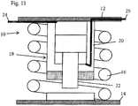
- Figure 1 shows a sectional view of a suspension unit 10, which is arranged between a car body 12 of a rail vehicle, which is no longer shown here, and a bogie 14, which is also only shown schematically here.
- the suspension unit consists of a spring 16 and a reciprocating piston element 18.
- the reciprocating piston element 18 in turn consists of a cylinder 20 and a piston 22 displaceably mounted in this Side of the piston 22 is conveyed into the cylinder 20.
- Hydraulic working media such as hydraulic oil or emulsions or pneumatic working media such as compressed air are used as the working medium in the context of the present invention. Any other common working medium for moving the reciprocating piston element can also be used.
- the pressure line 24 is in the Figure 1 illustrated embodiment arranged on the side of the bogie.
- an elastomer layer 26 is applied, which, as will be described later, can act as a damping element.
- FIG 1 the level control according to the invention with the suspension unit 10 is shown in regular driving mode.
- the reciprocating piston element 18 is retracted so far that it does not bridge the distance between the car body 12 and the bogie 14. This is clear here from the fact that the underside 28 of the piston 22 is not supported on the bogie 14.
- the height level of the rail vehicle is therefore only determined by the height of the spring 16, which is designed here as a steel spring.
- the reciprocating piston element 18 is now shown by extending the piston 22 in an operating mode in which the reciprocating piston element lifts the car body 12 relative to the bogie 14.
- the car body of the rail vehicle is raised to the maximum in that the working medium was pressed into the corresponding chamber of the cylinder 20 via the pressure line 24 and the piston 22 was thus extended to the maximum stop.
- the rail vehicle is raised to a desired maximum height, for example a platform platform.
- the suspension unit is shown in a state in which the spring 16 no longer works properly. This can take place, for example, as a result of an overload, ie excessive loading of the rail vehicle.
- the elastomer is used as emergency damping by forming an intermediate damping layer between the cylinder 20 and the bogie 14. This situation can also occur if the spring 16 is broken and can therefore no longer perform the spring function.
- FIG Figure 4 shows an alternative embodiment of the suspension unit 10.
- the reciprocating piston element 18 is arranged outside the spring 16 and parallel to it between the car body 12 and the bogie 14. Otherwise, this variant corresponds to that according to FIG Figure 1 .
- FIG. 5 shows the embodiment according to Figure 4 in the maximally extended state of the reciprocating piston element 18, in which the piston 22 is extended to its end position.
- FIG. 6 and 7th a further embodiment of the invention is shown, which essentially corresponds to the arrangement in FIG Figures 5 and 6 is equivalent to.
- the spring element 16 is not designed in the form of a steel spring but as an elastomer layer spring.
- the suspension unit is shown in a highly compressed state, which is due to the fact that the rail vehicle is relatively heavily loaded.
- the reciprocating piston element 18 is activated and fully extended.
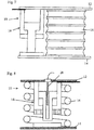
- Figure 8 Another embodiment is shown in Figure 8 shown.
- a displacement sensor 28 is also integrated in the reciprocating piston element 18.
- the piston 22 is designed to be hollow in the center for this purpose, so that the rod-shaped displacement sensor 28 can dip into the piston 22.
- the displacement sensor can be designed as an inductive measuring transducer here.
- any other position measuring system can also be used within the scope of the invention.
- Figure 9 is the embodiment according to Figure 8 in the event of overload or breakage of the spring element 16 and the simultaneous onset of emergency damping by the elastomer 26. This state is indicated by the displacement sensor 28 here.
- Figure 10 shows a variant in which the suspension unit is attached to the bogie and in which the pressure line 24 is also fed to the cylinder of the reciprocating piston element on the bogie 14.
- This embodiment variant also has a displacement sensor 28.
- Figure 11 shows the Figure 11 an embodiment variant corresponding to that according to Figure 1 , in which, however, the working medium is introduced into both chambers of the cylinder 20 via respective pressure lines 24 and 25 in order to be able to ensure a controlled retraction of the piston 22. Otherwise this embodiment corresponds to that according to FIG Figures 1 to 3 .
Landscapes
- Engineering & Computer Science (AREA)
- Mechanical Engineering (AREA)
- Vehicle Body Suspensions (AREA)
Claims (9)
- Véhicule sur rails avec une correction d'assiette avec des unités de suspension (10), qui sont disposées entre la caisse de wagon (12) et le bogie (14) du véhicule sur rails et sont constituées respectivement d'au moins un ressort (16) et d'au moins un élément formant piston alternatif (18) pneumatique ou hydraulique, dans lequel un milieu de travail est utilisé pour l'élément formant piston alternatif (18),
caractérisé en ce
que l'élément formant piston alternatif (18) est rentré en mode de déplacement si loin qu'il ne surmonte pas la distance entre la caisse de wagon (12) et le bogie (14). - Véhicule sur rails avec une correction d'assiette selon la revendication 1, caractérisé en ce que l'élément formant piston alternatif (18) de l'unité de suspension (10) est entouré par le ressort (16).
- Véhicule sur rails avec une correction d'assiette selon la revendication 1, caractérisé en ce que l'élément formant piston alternatif (18) de l'unité de suspension (10) est disposé à l'extérieur du ressort (16) de manière parallèle par rapport à celui-ci.
- Véhicule sur rails avec une correction d'assiette selon l'une quelconque des revendications 1 - 3, caractérisé en ce que le ressort (16) est réalisé en tant que ressort en acier, soufflet, élément en élastomère et/ou ressort hydropneumatique.
- Véhicule sur rails avec une correction d'assiette selon l'une quelconque des revendications précédentes, caractérisé en ce que l'amenée du milieu de travail est effectuée du côté de la caisse de wagon (12).
- Véhicule sur rails avec une correction d'assiette selon l'une quelconque des revendications précédentes, caractérisé en ce que l'amenée du milieu de travail est effectuée du côté du bogie (14).
- Véhicule sur rails avec une correction d'assiette selon l'une quelconque des revendications précédentes, caractérisé en ce que le milieu de travail pour l'élément formant piston alternatif (18) est liquide ou gazeux.
- Véhicule sur rails avec une correction d'assiette selon l'une quelconque des revendications précédentes, caractérisé en ce qu'un élastomère (26) est disposé en tant qu'élément d'amortissement d'urgence entre le bogie (14) et l'élément formant piston alternatif (18).
- Véhicule sur rails avec une correction d'assiette selon la revendication 8, caractérisé en ce qu'un système de mesure de distance parcourue coopère directement ou indirectement avec l'élément formant piston alternatif (18).
Applications Claiming Priority (2)
| Application Number | Priority Date | Filing Date | Title |
|---|---|---|---|
| DE102015013605.4A DE102015013605B4 (de) | 2015-10-21 | 2015-10-21 | Niveauregulierung |
| PCT/EP2016/001739 WO2017067662A1 (fr) | 2015-10-21 | 2016-10-20 | Dispositif de correction d'assiette |
Publications (2)
| Publication Number | Publication Date |
|---|---|
| EP3365218A1 EP3365218A1 (fr) | 2018-08-29 |
| EP3365218B1 true EP3365218B1 (fr) | 2021-09-22 |
Family
ID=57184399
Family Applications (1)
| Application Number | Title | Priority Date | Filing Date |
|---|---|---|---|
| EP16784793.8A Active EP3365218B1 (fr) | 2015-10-21 | 2016-10-20 | Dispositif de correction d'assiette |
Country Status (7)
| Country | Link |
|---|---|
| US (1) | US10882541B2 (fr) |
| EP (1) | EP3365218B1 (fr) |
| CN (1) | CN108349511B (fr) |
| CA (1) | CA3000282C (fr) |
| DE (1) | DE102015013605B4 (fr) |
| ES (1) | ES2901188T3 (fr) |
| WO (1) | WO2017067662A1 (fr) |
Families Citing this family (5)
| Publication number | Priority date | Publication date | Assignee | Title |
|---|---|---|---|---|
| WO2019091637A1 (fr) * | 2017-11-09 | 2019-05-16 | Knorr-Bremse Systeme für Schienenfahrzeuge GmbH | Système de réglage de niveau pour régler le niveau d'un véhicule, notamment d'un véhicule ferroviaire |
| FR3080077B1 (fr) | 2018-04-17 | 2020-09-18 | Alstom Transp Tech | Vehicule ferroviaire et procede de circulation associe |
| CN109204361B (zh) * | 2018-08-29 | 2020-04-14 | 中车青岛四方机车车辆股份有限公司 | 列车高度调节装置及列车高度调节方法 |
| FR3085932B1 (fr) * | 2018-09-14 | 2021-07-23 | Speedinnov | Suspension pneumatique pour vehicule ferroviaire |
| CN115649217B (zh) * | 2022-12-21 | 2023-03-10 | 济南工程职业技术学院 | 轨道车辆、转向架及其一系弹簧悬挂装置 |
Family Cites Families (21)
| Publication number | Priority date | Publication date | Assignee | Title |
|---|---|---|---|---|
| FI941446L (fi) | 1992-07-30 | 1994-03-29 | Man Ghh Schienenverkehr | Sekundäärijousitus kiskoajoneuvoja varten |
| AU1869097A (en) | 1995-12-12 | 1997-07-03 | Phoenix Aktiengesellschaft | Spring device |
| JPH10181596A (ja) * | 1998-02-16 | 1998-07-07 | Hitachi Ltd | 鉄道車両用軸ばね装置 |
| DE10056929A1 (de) | 2000-11-17 | 2002-05-29 | Knorr Bremse Systeme | Hydropneumatische Federungeinheit sowie hydropneumatisches Federungssystem |
| DE20105329U1 (de) | 2001-03-26 | 2001-06-07 | ZF Lemförder Metallwaren AG, 49448 Lemförde | Vorrichtung zur Federung und Niveauregulierung für Kraftfahrzeuge |
| DE10315000A1 (de) | 2002-04-26 | 2003-11-06 | Siemens Sgp Verkehrstech Gmbh | Niveauregulierung für ein Schienenfahrzeug |
| US6637348B1 (en) | 2002-07-02 | 2003-10-28 | Siemens Sgp Verkehrstechnik Gmbh | Level-adjustable main spring and actively biased emergency spring with fail-safe behavior |
| DE10238059B4 (de) | 2002-08-20 | 2014-02-13 | Liebherr-Aerospace Lindenberg Gmbh | Federelement |
| CN2597521Y (zh) * | 2003-01-29 | 2004-01-07 | 株洲时代新材料科技股份有限公司 | 一种钢弹簧加阻尼隔振器 |
| DE10360518B4 (de) | 2003-12-22 | 2007-08-23 | Knorr-Bremse Systeme für Schienenfahrzeuge GmbH | Vorrichtung zur Sekundärfederung eines Wagenkastens bei einem Schienenfahrzeug mit einem passiven Federelement |
| DE10360516C5 (de) | 2003-12-22 | 2010-12-16 | Knorr-Bremse Systeme für Schienenfahrzeuge GmbH | Vorrichtung zur Sekundärfederung eines Wagenkastens bei einem Schienenfahrzeug mit einem aktiven Federelement |
| DE102005018945A1 (de) | 2005-04-22 | 2006-10-26 | Knorr-Bremse Systeme für Schienenfahrzeuge GmbH | Vorrichtung zur Sekundärfederung eines Wagenkastens bei einem Schienenfahrzeug |
| DE202005009909U1 (de) | 2005-06-23 | 2006-10-26 | Liebherr-Aerospace Lindenberg Gmbh | Federsystem |
| DE102009043488A1 (de) | 2009-09-30 | 2011-05-05 | Bombardier Transportation Gmbh | Federanordnung zur Niveauregulierung in einem Fahrzeug |
| CN201914046U (zh) * | 2010-12-29 | 2011-08-03 | 刘道德 | 一种机动车升降悬挂装置 |
| CA2827898C (fr) * | 2011-02-22 | 2018-01-16 | Tec Tran Brake Corp. | Vehicule ferroviaire de mise a niveau et systemes et procedes s'y rapportant |
| US20130009350A1 (en) * | 2011-07-08 | 2013-01-10 | Friedrich Peter Wolf-Monheim | Semiactive Wheel Suspension |
| DE102013210556B4 (de) * | 2012-08-01 | 2015-03-19 | Ford Global Technologies, Llc | Vorrichtung zur Höhenverstellung eines Fahrzeugaufbaus |
| DE102013215360B4 (de) * | 2012-09-10 | 2015-09-10 | Ford Global Technologies, Llc | Höhenverstellvorrichtung für Fahrzeuge mit Luftfeder und Schwingungsdämpfer |
| CN103016607A (zh) * | 2012-12-24 | 2013-04-03 | 浙江金波减震器制造有限公司 | 一种减震装置 |
| US11445491B2 (en) | 2019-07-25 | 2022-09-13 | Qualcomm Incorporated | Reduced capability/complexity NR bandwidth part configuration |
-
2015
- 2015-10-21 DE DE102015013605.4A patent/DE102015013605B4/de not_active Expired - Fee Related
-
2016
- 2016-10-20 CN CN201680061338.5A patent/CN108349511B/zh active Active
- 2016-10-20 ES ES16784793T patent/ES2901188T3/es active Active
- 2016-10-20 CA CA3000282A patent/CA3000282C/fr active Active
- 2016-10-20 US US15/770,115 patent/US10882541B2/en active Active
- 2016-10-20 WO PCT/EP2016/001739 patent/WO2017067662A1/fr not_active Ceased
- 2016-10-20 EP EP16784793.8A patent/EP3365218B1/fr active Active
Also Published As
| Publication number | Publication date |
|---|---|
| CN108349511B (zh) | 2021-04-02 |
| WO2017067662A1 (fr) | 2017-04-27 |
| US20180312175A1 (en) | 2018-11-01 |
| DE102015013605B4 (de) | 2018-08-23 |
| CA3000282C (fr) | 2023-12-19 |
| EP3365218A1 (fr) | 2018-08-29 |
| ES2901188T3 (es) | 2022-03-21 |
| CN108349511A (zh) | 2018-07-31 |
| CA3000282A1 (fr) | 2017-04-27 |
| DE102015013605A1 (de) | 2017-04-27 |
| US10882541B2 (en) | 2021-01-05 |
Similar Documents
| Publication | Publication Date | Title |
|---|---|---|
| EP3365218B1 (fr) | Dispositif de correction d'assiette | |
| EP0663877B1 (fr) | Commande de niveau et d'inclinaison d'une caisse de wagon | |
| DE10360516C5 (de) | Vorrichtung zur Sekundärfederung eines Wagenkastens bei einem Schienenfahrzeug mit einem aktiven Federelement | |
| EP2414208B1 (fr) | Véhicule à compensation du roulis | |
| DE102013222705B4 (de) | Fahrzeugaufhängungssystem | |
| EP2483125B1 (fr) | Système amortisseur pour la régulation de niveau dans un véhicule | |
| EP1075407A1 (fr) | Dispositif anti-roulis pour chassis de bogie d'un vehicule ferroviaire | |
| DE10360518B4 (de) | Vorrichtung zur Sekundärfederung eines Wagenkastens bei einem Schienenfahrzeug mit einem passiven Federelement | |
| DE102015016024A1 (de) | Federsystem eines Schienenfahrzeuges | |
| EP1918137B1 (fr) | Remorqueur d'aéroport doté d'une suspension à air | |
| EP4339056A1 (fr) | Véhicule ferroviaire doté d'un châssis et d'un dispositif de compensation de roulis ainsi que dispositif de compensation de roulis, en particulier pour un véhicule ferroviaire | |
| DE10315000A1 (de) | Niveauregulierung für ein Schienenfahrzeug | |
| EP2703245A2 (fr) | Système de suspension pneumatique pour un véhicule ferroviaire | |
| EP2861476B1 (fr) | Véhicule pourvu d'un système à ressort présentant une caractéristique de ressort transversal pouvant être prédéfinie | |
| DE10360517B4 (de) | Vorrichtung zur Sekundärfederung eines Wagenkastens bei einem Schienenfahrzeug mit einem aktiven Federelement | |
| EP2353962A1 (fr) | Agencement de chassis pour un véhicule sur rail | |
| DE3510454A1 (de) | Drehgestell und schienenfahrzeug sowie verfahren zum notabstuetzen | |
| WO2013079480A1 (fr) | Dispositif à ressort hélicoïdal pour un véhicule | |
| DE202015101275U1 (de) | Niveauerzwingungseinrichtung | |
| CH670227A5 (en) | Rail vehicle superstructure transverse movement limiting equipment | |
| AT407032B (de) | Federung für ein schienenfahrzeug | |
| EP1897776B1 (fr) | Bogie | |
| WO2019007600A1 (fr) | Ressort pneumatique, en particulier pour véhicules routiers et/ou pour véhicules ferroviaires | |
| DE19956039B4 (de) | Radfederung mit Zentralfeder für ein Fahrzeug | |
| AT501225B1 (de) | Niveauregulierbare hauptfeder und aktiv vorgespannte notfeder mit ausfallsicherem verhalten |
Legal Events
| Date | Code | Title | Description |
|---|---|---|---|
| STAA | Information on the status of an ep patent application or granted ep patent |
Free format text: STATUS: UNKNOWN |
|
| STAA | Information on the status of an ep patent application or granted ep patent |
Free format text: STATUS: THE INTERNATIONAL PUBLICATION HAS BEEN MADE |
|
| PUAI | Public reference made under article 153(3) epc to a published international application that has entered the european phase |
Free format text: ORIGINAL CODE: 0009012 |
|
| STAA | Information on the status of an ep patent application or granted ep patent |
Free format text: STATUS: REQUEST FOR EXAMINATION WAS MADE |
|
| 17P | Request for examination filed |
Effective date: 20180504 |
|
| AK | Designated contracting states |
Kind code of ref document: A1 Designated state(s): AL AT BE BG CH CY CZ DE DK EE ES FI FR GB GR HR HU IE IS IT LI LT LU LV MC MK MT NL NO PL PT RO RS SE SI SK SM TR |
|
| AX | Request for extension of the european patent |
Extension state: BA ME |
|
| DAV | Request for validation of the european patent (deleted) | ||
| DAX | Request for extension of the european patent (deleted) | ||
| RIC1 | Information provided on ipc code assigned before grant |
Ipc: B61F 5/14 20060101ALI20200825BHEP Ipc: B61F 5/22 20060101AFI20200825BHEP Ipc: B61F 5/06 20060101ALI20200825BHEP |
|
| STAA | Information on the status of an ep patent application or granted ep patent |
Free format text: STATUS: EXAMINATION IS IN PROGRESS |
|
| 17Q | First examination report despatched |
Effective date: 20201020 |
|
| GRAP | Despatch of communication of intention to grant a patent |
Free format text: ORIGINAL CODE: EPIDOSNIGR1 |
|
| STAA | Information on the status of an ep patent application or granted ep patent |
Free format text: STATUS: GRANT OF PATENT IS INTENDED |
|
| INTG | Intention to grant announced |
Effective date: 20210416 |
|
| GRAS | Grant fee paid |
Free format text: ORIGINAL CODE: EPIDOSNIGR3 |
|
| GRAA | (expected) grant |
Free format text: ORIGINAL CODE: 0009210 |
|
| STAA | Information on the status of an ep patent application or granted ep patent |
Free format text: STATUS: THE PATENT HAS BEEN GRANTED |
|
| AK | Designated contracting states |
Kind code of ref document: B1 Designated state(s): AL AT BE BG CH CY CZ DE DK EE ES FI FR GB GR HR HU IE IS IT LI LT LU LV MC MK MT NL NO PL PT RO RS SE SI SK SM TR |
|
| REG | Reference to a national code |
Ref country code: GB Ref legal event code: FG4D Free format text: NOT ENGLISH |
|
| REG | Reference to a national code |
Ref country code: DE Ref legal event code: R096 Ref document number: 502016013885 Country of ref document: DE |
|
| REG | Reference to a national code |
Ref country code: IE Ref legal event code: FG4D Free format text: LANGUAGE OF EP DOCUMENT: GERMAN |
|
| REG | Reference to a national code |
Ref country code: CH Ref legal event code: EP Ref country code: AT Ref legal event code: REF Ref document number: 1432115 Country of ref document: AT Kind code of ref document: T Effective date: 20211015 |
|
| REG | Reference to a national code |
Ref country code: LT Ref legal event code: MG9D |
|
| REG | Reference to a national code |
Ref country code: NL Ref legal event code: MP Effective date: 20210922 |
|
| PG25 | Lapsed in a contracting state [announced via postgrant information from national office to epo] |
Ref country code: RS Free format text: LAPSE BECAUSE OF FAILURE TO SUBMIT A TRANSLATION OF THE DESCRIPTION OR TO PAY THE FEE WITHIN THE PRESCRIBED TIME-LIMIT Effective date: 20210922 Ref country code: SE Free format text: LAPSE BECAUSE OF FAILURE TO SUBMIT A TRANSLATION OF THE DESCRIPTION OR TO PAY THE FEE WITHIN THE PRESCRIBED TIME-LIMIT Effective date: 20210922 Ref country code: HR Free format text: LAPSE BECAUSE OF FAILURE TO SUBMIT A TRANSLATION OF THE DESCRIPTION OR TO PAY THE FEE WITHIN THE PRESCRIBED TIME-LIMIT Effective date: 20210922 Ref country code: FI Free format text: LAPSE BECAUSE OF FAILURE TO SUBMIT A TRANSLATION OF THE DESCRIPTION OR TO PAY THE FEE WITHIN THE PRESCRIBED TIME-LIMIT Effective date: 20210922 Ref country code: NO Free format text: LAPSE BECAUSE OF FAILURE TO SUBMIT A TRANSLATION OF THE DESCRIPTION OR TO PAY THE FEE WITHIN THE PRESCRIBED TIME-LIMIT Effective date: 20211222 Ref country code: LT Free format text: LAPSE BECAUSE OF FAILURE TO SUBMIT A TRANSLATION OF THE DESCRIPTION OR TO PAY THE FEE WITHIN THE PRESCRIBED TIME-LIMIT Effective date: 20210922 Ref country code: BG Free format text: LAPSE BECAUSE OF FAILURE TO SUBMIT A TRANSLATION OF THE DESCRIPTION OR TO PAY THE FEE WITHIN THE PRESCRIBED TIME-LIMIT Effective date: 20211222 |
|
| PG25 | Lapsed in a contracting state [announced via postgrant information from national office to epo] |
Ref country code: LV Free format text: LAPSE BECAUSE OF FAILURE TO SUBMIT A TRANSLATION OF THE DESCRIPTION OR TO PAY THE FEE WITHIN THE PRESCRIBED TIME-LIMIT Effective date: 20210922 Ref country code: GR Free format text: LAPSE BECAUSE OF FAILURE TO SUBMIT A TRANSLATION OF THE DESCRIPTION OR TO PAY THE FEE WITHIN THE PRESCRIBED TIME-LIMIT Effective date: 20211223 |
|
| REG | Reference to a national code |
Ref country code: ES Ref legal event code: FG2A Ref document number: 2901188 Country of ref document: ES Kind code of ref document: T3 Effective date: 20220321 |
|
| PG25 | Lapsed in a contracting state [announced via postgrant information from national office to epo] |
Ref country code: IS Free format text: LAPSE BECAUSE OF FAILURE TO SUBMIT A TRANSLATION OF THE DESCRIPTION OR TO PAY THE FEE WITHIN THE PRESCRIBED TIME-LIMIT Effective date: 20220122 Ref country code: SK Free format text: LAPSE BECAUSE OF FAILURE TO SUBMIT A TRANSLATION OF THE DESCRIPTION OR TO PAY THE FEE WITHIN THE PRESCRIBED TIME-LIMIT Effective date: 20210922 Ref country code: RO Free format text: LAPSE BECAUSE OF FAILURE TO SUBMIT A TRANSLATION OF THE DESCRIPTION OR TO PAY THE FEE WITHIN THE PRESCRIBED TIME-LIMIT Effective date: 20210922 Ref country code: PT Free format text: LAPSE BECAUSE OF FAILURE TO SUBMIT A TRANSLATION OF THE DESCRIPTION OR TO PAY THE FEE WITHIN THE PRESCRIBED TIME-LIMIT Effective date: 20220124 Ref country code: PL Free format text: LAPSE BECAUSE OF FAILURE TO SUBMIT A TRANSLATION OF THE DESCRIPTION OR TO PAY THE FEE WITHIN THE PRESCRIBED TIME-LIMIT Effective date: 20210922 Ref country code: NL Free format text: LAPSE BECAUSE OF FAILURE TO SUBMIT A TRANSLATION OF THE DESCRIPTION OR TO PAY THE FEE WITHIN THE PRESCRIBED TIME-LIMIT Effective date: 20210922 Ref country code: EE Free format text: LAPSE BECAUSE OF FAILURE TO SUBMIT A TRANSLATION OF THE DESCRIPTION OR TO PAY THE FEE WITHIN THE PRESCRIBED TIME-LIMIT Effective date: 20210922 Ref country code: CZ Free format text: LAPSE BECAUSE OF FAILURE TO SUBMIT A TRANSLATION OF THE DESCRIPTION OR TO PAY THE FEE WITHIN THE PRESCRIBED TIME-LIMIT Effective date: 20210922 Ref country code: AL Free format text: LAPSE BECAUSE OF FAILURE TO SUBMIT A TRANSLATION OF THE DESCRIPTION OR TO PAY THE FEE WITHIN THE PRESCRIBED TIME-LIMIT Effective date: 20210922 |
|
| REG | Reference to a national code |
Ref country code: DE Ref legal event code: R097 Ref document number: 502016013885 Country of ref document: DE Ref country code: BE Ref legal event code: MM Effective date: 20211031 |
|
| PG25 | Lapsed in a contracting state [announced via postgrant information from national office to epo] |
Ref country code: MC Free format text: LAPSE BECAUSE OF FAILURE TO SUBMIT A TRANSLATION OF THE DESCRIPTION OR TO PAY THE FEE WITHIN THE PRESCRIBED TIME-LIMIT Effective date: 20210922 |
|
| PG25 | Lapsed in a contracting state [announced via postgrant information from national office to epo] |
Ref country code: DK Free format text: LAPSE BECAUSE OF FAILURE TO SUBMIT A TRANSLATION OF THE DESCRIPTION OR TO PAY THE FEE WITHIN THE PRESCRIBED TIME-LIMIT Effective date: 20210922 Ref country code: BE Free format text: LAPSE BECAUSE OF NON-PAYMENT OF DUE FEES Effective date: 20211031 Ref country code: LU Free format text: LAPSE BECAUSE OF NON-PAYMENT OF DUE FEES Effective date: 20211020 |
|
| PLBE | No opposition filed within time limit |
Free format text: ORIGINAL CODE: 0009261 |
|
| STAA | Information on the status of an ep patent application or granted ep patent |
Free format text: STATUS: NO OPPOSITION FILED WITHIN TIME LIMIT |
|
| GBPC | Gb: european patent ceased through non-payment of renewal fee |
Effective date: 20211222 |
|
| 26N | No opposition filed |
Effective date: 20220623 |
|
| PG25 | Lapsed in a contracting state [announced via postgrant information from national office to epo] |
Ref country code: IE Free format text: LAPSE BECAUSE OF NON-PAYMENT OF DUE FEES Effective date: 20211020 Ref country code: GB Free format text: LAPSE BECAUSE OF NON-PAYMENT OF DUE FEES Effective date: 20211222 |
|
| PG25 | Lapsed in a contracting state [announced via postgrant information from national office to epo] |
Ref country code: SI Free format text: LAPSE BECAUSE OF FAILURE TO SUBMIT A TRANSLATION OF THE DESCRIPTION OR TO PAY THE FEE WITHIN THE PRESCRIBED TIME-LIMIT Effective date: 20210922 |
|
| PG25 | Lapsed in a contracting state [announced via postgrant information from national office to epo] |
Ref country code: IT Free format text: LAPSE BECAUSE OF FAILURE TO SUBMIT A TRANSLATION OF THE DESCRIPTION OR TO PAY THE FEE WITHIN THE PRESCRIBED TIME-LIMIT Effective date: 20210922 |
|
| PG25 | Lapsed in a contracting state [announced via postgrant information from national office to epo] |
Ref country code: HU Free format text: LAPSE BECAUSE OF FAILURE TO SUBMIT A TRANSLATION OF THE DESCRIPTION OR TO PAY THE FEE WITHIN THE PRESCRIBED TIME-LIMIT; INVALID AB INITIO Effective date: 20161020 |
|
| PG25 | Lapsed in a contracting state [announced via postgrant information from national office to epo] |
Ref country code: CY Free format text: LAPSE BECAUSE OF FAILURE TO SUBMIT A TRANSLATION OF THE DESCRIPTION OR TO PAY THE FEE WITHIN THE PRESCRIBED TIME-LIMIT Effective date: 20210922 |
|
| PG25 | Lapsed in a contracting state [announced via postgrant information from national office to epo] |
Ref country code: SM Free format text: LAPSE BECAUSE OF FAILURE TO SUBMIT A TRANSLATION OF THE DESCRIPTION OR TO PAY THE FEE WITHIN THE PRESCRIBED TIME-LIMIT Effective date: 20210922 |
|
| PG25 | Lapsed in a contracting state [announced via postgrant information from national office to epo] |
Ref country code: MK Free format text: LAPSE BECAUSE OF FAILURE TO SUBMIT A TRANSLATION OF THE DESCRIPTION OR TO PAY THE FEE WITHIN THE PRESCRIBED TIME-LIMIT Effective date: 20210922 |
|
| PG25 | Lapsed in a contracting state [announced via postgrant information from national office to epo] |
Ref country code: MT Free format text: LAPSE BECAUSE OF FAILURE TO SUBMIT A TRANSLATION OF THE DESCRIPTION OR TO PAY THE FEE WITHIN THE PRESCRIBED TIME-LIMIT Effective date: 20210922 |
|
| REG | Reference to a national code |
Ref country code: CH Ref legal event code: U11 Free format text: ST27 STATUS EVENT CODE: U-0-0-U10-U11 (AS PROVIDED BY THE NATIONAL OFFICE) Effective date: 20251101 |
|
| PG25 | Lapsed in a contracting state [announced via postgrant information from national office to epo] |
Ref country code: TR Free format text: LAPSE BECAUSE OF FAILURE TO SUBMIT A TRANSLATION OF THE DESCRIPTION OR TO PAY THE FEE WITHIN THE PRESCRIBED TIME-LIMIT Effective date: 20210922 |
|
| PGFP | Annual fee paid to national office [announced via postgrant information from national office to epo] |
Ref country code: DE Payment date: 20251030 Year of fee payment: 10 |
|
| PGFP | Annual fee paid to national office [announced via postgrant information from national office to epo] |
Ref country code: AT Payment date: 20251023 Year of fee payment: 10 |
|
| PGFP | Annual fee paid to national office [announced via postgrant information from national office to epo] |
Ref country code: FR Payment date: 20251024 Year of fee payment: 10 |
|
| PGFP | Annual fee paid to national office [announced via postgrant information from national office to epo] |
Ref country code: CH Payment date: 20251101 Year of fee payment: 10 |
|
| PGFP | Annual fee paid to national office [announced via postgrant information from national office to epo] |
Ref country code: ES Payment date: 20251103 Year of fee payment: 10 |