EP0794309A1 - Ferrure à arrêt pour un volet articulé autour d'un axe horizontal à la paroi de plafond d'une armoire - Google Patents
Ferrure à arrêt pour un volet articulé autour d'un axe horizontal à la paroi de plafond d'une armoire Download PDFInfo
- Publication number
- EP0794309A1 EP0794309A1 EP97102297A EP97102297A EP0794309A1 EP 0794309 A1 EP0794309 A1 EP 0794309A1 EP 97102297 A EP97102297 A EP 97102297A EP 97102297 A EP97102297 A EP 97102297A EP 0794309 A1 EP0794309 A1 EP 0794309A1
- Authority
- EP
- European Patent Office
- Prior art keywords
- lever
- flap
- fitting according
- holding fitting
- lever arm
- Prior art date
- Legal status (The legal status is an assumption and is not a legal conclusion. Google has not performed a legal analysis and makes no representation as to the accuracy of the status listed.)
- Granted
Links
Images


Classifications
-
- E—FIXED CONSTRUCTIONS
- E05—LOCKS; KEYS; WINDOW OR DOOR FITTINGS; SAFES
- E05D—HINGES OR SUSPENSION DEVICES FOR DOORS, WINDOWS OR WINGS
- E05D3/00—Hinges with pins
- E05D3/02—Hinges with pins with one pin
-
- E—FIXED CONSTRUCTIONS
- E05—LOCKS; KEYS; WINDOW OR DOOR FITTINGS; SAFES
- E05D—HINGES OR SUSPENSION DEVICES FOR DOORS, WINDOWS OR WINGS
- E05D15/00—Suspension arrangements for wings
- E05D15/26—Suspension arrangements for wings for folding wings
- E05D15/262—Suspension arrangements for wings for folding wings folding vertically
-
- E—FIXED CONSTRUCTIONS
- E05—LOCKS; KEYS; WINDOW OR DOOR FITTINGS; SAFES
- E05Y—INDEXING SCHEME ASSOCIATED WITH SUBCLASSES E05D AND E05F, RELATING TO CONSTRUCTION ELEMENTS, ELECTRIC CONTROL, POWER SUPPLY, POWER SIGNAL OR TRANSMISSION, USER INTERFACES, MOUNTING OR COUPLING, DETAILS, ACCESSORIES, AUXILIARY OPERATIONS NOT OTHERWISE PROVIDED FOR, APPLICATION THEREOF
- E05Y2900/00—Application of doors, windows, wings or fittings thereof
- E05Y2900/20—Application of doors, windows, wings or fittings thereof for furniture, e.g. cabinets
Definitions
- the invention relates to a mounting bracket for a pivotable about a horizontal pivot axis, hinged to a top wall of a cabinet flap, consisting of a hinged to the body part of the cabinet lever, the free end in a perpendicular to the pivot axis on the inside of the flap attachable rail and which is acted upon by a resilient device, which preferably consists of a rod which can be extended from a spring cylinder by gas or spring force and which can be pressed into it.
- a mounting bracket for a flap is known, the one from a handlebar, one end of which upper edge region of the flap and the other end of which is articulated at a recessed position with the top of the cabinet, and on the other hand consists of a spring-loaded lever arm articulated at one end on a side wall, the other end of which is at a distance from the articulation point of the handlebar with the flap is articulated so that the flap is connected by the handlebar and the lever arm to the cabinet body via four joints and can thus be pivoted out of its vertical closed position into an open position in which it is located obliquely above the body part.
- the complicated pivoting mechanism there must still be enough space above the cabinet when pivoting the flap with this known retaining fitting in order to be able to pivot the flap into its open position.
- a holding fitting for a flap is known, in which this is guided on the one hand in its central area by a handlebar with the upper part of the cabinet and on the other hand with its lower area by two links in the side guide rails of the side walls of the body part is, so that the flap can be pivoted outwards with its upper end.
- This mounting bracket also consists of a complicated joint system, with additional weight compensation for the flap pivoting outward over the head of the user.
- the object of the invention is to provide a retaining fitting of the type mentioned, which can be installed in a space-saving manner and which only presses and holds the flap into the open position after pivoting through a certain opening angle.
- this object is achieved with a retaining fitting Initially specified type solved in that the lever consists of a two-armed angle lever, the pivot axis between the lever arms, the longer lever arm is guided in the rail and on the shorter lever arm pointing in the closed state of the flap into the interior of the cabinet one end of the resilient Device is articulated, the other end is articulated to the furniture body.
- the retaining fitting according to the invention can be installed in a space-saving manner in the upper area of the body part of the cabinet without cantilevered parts appearing, which impair access to the cabinet or the storage space. Due to the characteristic of the extension of the shorter lever arm pointing into the interior of the cabinet on this articulated rod guided in the spring cylinder, when opening the resilient device does not exert any greater moment on the flap, pivoting it into the open position, so that an undesired opening is avoided.
- the two lever arms of the angle lever enclose an obtuse angle, the line of action of the spring force running above the pivot axis of the angle lever when the flap is closed, so that the resilient device in the closed position of the flap exerts a moment acting on it in the closing direction, through which the Flap is held in its closed position and that must be overcome when opening the flap before the resilient device exerts a moment acting in the opening direction on the shorter lever arm after passing through the dead center position.
- the length of the longer lever arm is expediently adjustable, so that it can be easily and quickly adapted to different lengths of the flaps.
- the spring cylinder and the angle lever are pivotably mounted between upstanding legs in a fastening plate.
- the fastening plate can then be fastened either in the middle area or adjacent to a side wall on the cover plate of the body part.
- a mounting plate in such a way that the spring cylinder and the angle lever can be attached to a side wall.
- a stop pin for the angle lever is expediently held between the legs above the bearing axis of the angle lever. This stop pin limits the swivel angle and thus relieves the hinges connecting the flap to the top wall.
- the stop pin is rotatably mounted and has an eccentric shaft. This configuration simplifies the assembly of the retaining fitting because, with a corresponding rotation of the eccentric shaft, the spring cylinder can be installed with the rod extended to the stop.
- the retaining fitting according to the invention is also particularly suitable as a lifting device for a two-leaf folding flap.
- a lifting device for a two-leaf flap which consists of an angle lever, on the shorter arm of which the rod of a spring cylinder is articulated and on the longer arm of which a sleeve is telescopically extendable, the front end of which is articulated with the lower wing of the two-leaf flap is connected.
- This known retaining fitting affects the free access to the inside of the cabinet.
- the flap is the upper wing of a two-wing folding flap, the lower wing of which is articulated on a support part which is guided in a guide rail articulated on the side wall of the body part.
- the characteristics of the resilient device can be selected so that the two-leaf folding flap automatically swivels under the spring force into the open position after a short pull-out and lifting of the lower leaf.
- the support part is provided with an elongated slide part, the width of which is provided in its central region for locking it in a C-shaped guide rail with a hammer-shaped head which can be rotated by a bolt about an axis perpendicular to the guide rail is smaller and its length is greater than the width of the longitudinal slot formed between the webs angled by the legs of the guide rail, and of a holding part connected to the slide part for fastening a fitting part carrying the door leaf, preferably a hinge arm.
- a supporting part is known from DE-OS 43 24 340, to which reference is made for a more detailed description.
- the slide part is preferably provided with a bearing part passing through the longitudinal slot, in which the holding part is pivotably mounted about an axis running transversely to the slide part.
- a support part which is easier to assemble, is known from DE-296 02 424.4, to which reference is made for a more detailed illustration of the support part.
- An essential feature of the present invention is that only the upper door leaf is supported by the retaining fitting and that the lower door leaf is guided in vertical guide rails of the side walls by the support parts described in DE-OS 43 24 340 and DE-296 02 424.4 .
- the user therefore only needs to pull the lower door leaf towards him via an appropriate door handle so that both door leaves are pivoted over the head of the user when opening, without projecting significantly from the furniture body.
- both the retaining fitting and the side guide rails with the support parts can be present twice, that is to say connected to both lateral end regions of the flap or the two-leaf folding flap.
- the length of the shorter lever arm of the two-armed angle lever is adjustable.
- the shorter lever arm is expediently also adjustable or adjustable in its angular position to the longer lever arm.
- an adjustment part can be guided, which is provided with a bore for articulating the resilient device.
- the shorter lever arm is expediently provided with two elongated holes, the adjusting part enclosing the shorter lever arm in a U-shaped manner and pins which pass through the elongated holes and are guided in the legs of the adjusting part.
- the elongated holes can be inclined to one another in such a way that the adjusting part is displaced on an arc on the shorter lever arm becomes. This type of shift is appropriate so as not to change the characteristic of the gas spring.
- a rotatable eccentric disc is mounted on the angle lever, which engages in a bore or an elongated hole of the adjustment part and is provided for its rotation, for example with a screwdriver with a slot or a cross recess.
- the eccentric disk is expediently held non-positively with its shaft in a bore in the bell crank so that it can only be rotated after a frictional force has been overcome.
- the holding fitting according to the invention can also be used as a closing or opening device for sliding sliding doors which can be pivoted about vertical axes.
- the resilient device or the gas spring only needs to exert a smaller force, since this does not have to hold or overcome the door weight.
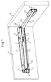
- the holding fitting consists of an essentially rectangular fastening plate 1, which is connected to two webs or legs 2 which run parallel to one another and are at right angles thereon.
- the legs 2 are provided with bush-like widenings 3, through which aligned transverse bores 4 pass.
- a bolt is held in these transverse bores, on which the rear end of the spring cylinder 5 is pivotably mounted via a web 6 that is understood as having a bearing bore.
- the legs 2 are provided with aligned transverse bores, in which a bearing pin 7 is held, on which an angle lever 8 is pivotably mounted.
- the angle lever 8 consists of a shorter lever arm 9 and a longer lever arm 10 which is provided at its free end with two rollers 11 mounted on a pin passing through it in a transverse bore.
- the shorter lever arm 9 has a bifurcated end, between the legs of which a bolt is held in aligned bores, on which the front end of the rod 12, which is displaceably guided in the spring cylinder 5, is mounted in a transverse bore.
- the resilient device consisting of the spring cylinder 5 and the rod 12 guided in it can be a gas spring or else a device in which a helical spring is clamped in the spring cylinder 5 between its base and the rod.
- the fastening plate is provided on both sides of the legs 2 with fastening bores 13, via which it can be fastened in the middle by means of fastening screws to the cover plate 14 of a cabinet or possibly near a side wall.
- a flap 16 is connected to the cover plate 14 by means of conventional handle-cup hinges 15 so as to be pivotable about a horizontal axis.
- a C-shaped guide rail 17 is fastened, in which the rollers 11 of the longer lever arm 10 of the angle lever 8 are guided.
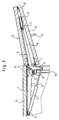
- the lever arms 9, 10 of the angle lever 8 enclose an obtuse angle, as can be seen from FIGS. 3 and 7.
- the legs are provided with further aligned bores 19, in which a bolt 20 is held with an eccentric shaft part 21.
- the bolt 20 can be rotated by a screwdriver so that the eccentricity of the shaft 21 can be adjusted.
- the pin 20 serves in the manner shown in FIG. 3 as a stop for the angle lever 8 in the open position.
- an angle lever can be seen, the longer arm of which is adjustable.
- the base body 24 of the angle lever has a U-shaped cross section.
- the displaceable extension part 26 is displaceably guided between the lateral legs of the longer lever arm 25.
- the extension part 26 has an elongated hole 27 which penetrates a pin 28 which is held in the legs of the longer arm 25.
- the longer arm is provided in its web part with an elongated hole 29 which penetrates a fixing screw 31 which can be screwed into a threaded bore 30 of the extension part 26 and whose widespread head is supported on the edges of the elongated hole 29.
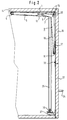
- the flap 16 forms the upper wing of a two-leaf folding flap
- the lower one Wing 32 is connected by a hinge strap 33 to the upper wing 16.
- the lower wing is provided with a handle 34 in its middle area on its outside.
- a C-shaped guide rail 35 is fastened parallel to the opening edges, in which a supporting part 36 is slidably guided, which is connected to the lower edge region of the lower wing via a conventional four-articulated double-link hinge 37. Because of the closer design of the support parts 36 and their connection by the hinges 37 to the lower wings and the design of the guide rails 35, reference is made to DE-OS 43 24 340 and DE-296 02 424.4.
- the spring cylinder with the rod displaceably guided against spring force in the closed state of the flaps extends approximately parallel to the top wall 14 into the interior of the cabinet. Due to the obtuse angle that the arms 9, 10 of the angle lever 8 enclose, the resilient device exerts a closing moment on the flaps in the closed position.
- the shorter lever arm of the angle lever 8 in the open position projects only slightly beyond the lower wing of the folding flap, so that access to the interior of the cabinet is hardly impaired by the lifting retaining fitting according to the invention.
- the longer lever arm 10 lies close to the upper wing 16 both in the closed position and in the open position of the folding flap, so that it takes up little space.
- the eccentric pin 20 not only forms a stop, but it can also be rotated for the purpose of assembly into a position in which the gas spring or spring device extended to its greatest length can be mounted. After assembly, the eccentric bolt is turned to a position in which the angle lever is supported on it under pretension.
- the mounting plate 1 is first attached to the inside of the cover plate.
- the mounting plate can be moved for depth adjustment via the elongated holes.
- the angle lever is advantageously already stored between the legs of the mounting plate.
- the gas spring or the resilient device is mounted in the extended position.
- the longer lever arm of the angle lever is pivoted by a small angle into the closed position by hand and the bolt 20 is rotated by a small angle into a position in which the longer lever arm is supported on it under spring force.
- the upper door leaf is expediently articulated on the top wall via conventional hinges, preferably so-called clip hinges.
- the lower door wing is then connected to the support member in a known manner.
- the angle lever 40 shown in FIG. 8 consists of a one-piece base body 41 shown in FIG. 9.
- This base body can be punched out of a thicker sheet or it can also consist of a package of thinner sheets which are then riveted together to form a base body.
- the longer lever arm is provided with a bead 42 for stiffening.
- the adjustment part 43 is guided displaceably on the base body 41.
- the adjustment part 43 consists of a U-shaped bent middle part 44, with which it surrounds the shorter lever arm 45 of the base body 41.
- the shorter lever arm 45 is provided in the manner shown in FIG. 9 with two oblong holes 46 arranged at an angle to one another.
- two pins are riveted in aligned bores 49 which pass through the elongated holes 46.
- the adjusting part 43 has aligned bores 50 at its free forked end for articulating the piston rod of the gas spring.
- the leg 48 of the adjustment part 43 is extended and provided with an elongated hole 51.
- a circular disc-shaped and provided with a cross slot eccentric 52 the eccentric shaft is riveted in a bore 53 of the longer lever arm so that it is held in this frictionally but rotatably.
- the elongated holes 46 are inclined to one another in such a way that when the eccentric 42 rotates, the adjusting part 43 is displaced approximately on the dash-dotted circular line 54 in FIG. 8.
- the adjustment part is shown in Fig. 8 in dashed lines in its extended position.
Landscapes
- Engineering & Computer Science (AREA)
- Mechanical Engineering (AREA)
- Hinges (AREA)
- Closing And Opening Devices For Wings, And Checks For Wings (AREA)
- Support Devices For Sliding Doors (AREA)
- Hinge Accessories (AREA)
- Control Of Vending Devices And Auxiliary Devices For Vending Devices (AREA)
- Wing Frames And Configurations (AREA)
Applications Claiming Priority (2)
| Application Number | Priority Date | Filing Date | Title |
|---|---|---|---|
| DE29604354U DE29604354U1 (de) | 1996-03-08 | 1996-03-08 | Haltebeschlag für eine um eine horizontale Schwenkachse an einer Deckwand eines Schranks angelenkte Klappe |
| DE29604354U | 1996-03-08 |
Publications (2)
| Publication Number | Publication Date |
|---|---|
| EP0794309A1 true EP0794309A1 (fr) | 1997-09-10 |
| EP0794309B1 EP0794309B1 (fr) | 2004-09-08 |
Family
ID=8020779
Family Applications (1)
| Application Number | Title | Priority Date | Filing Date |
|---|---|---|---|
| EP97102297A Expired - Lifetime EP0794309B1 (fr) | 1996-03-08 | 1997-02-13 | Ferrure à arrêt pour un volet articulé autour d'un axe horizontal à la paroi de plafond d'une armoire |
Country Status (13)
| Country | Link |
|---|---|
| US (1) | US5882099A (fr) |
| EP (1) | EP0794309B1 (fr) |
| JP (1) | JP2987338B2 (fr) |
| KR (1) | KR100202764B1 (fr) |
| AT (1) | ATE275687T1 (fr) |
| BR (1) | BR9701235A (fr) |
| CZ (1) | CZ294594B6 (fr) |
| DE (2) | DE29604354U1 (fr) |
| ES (1) | ES2229291T3 (fr) |
| HU (1) | HU219781B (fr) |
| PL (1) | PL182337B1 (fr) |
| SI (1) | SI9700044A (fr) |
| TW (1) | TW328977B (fr) |
Cited By (2)
| Publication number | Priority date | Publication date | Assignee | Title |
|---|---|---|---|---|
| US6877830B2 (en) | 2001-01-15 | 2005-04-12 | Arturo Salice S.P.A. | Lifting apparatus for a two-leaf folding flap |
| EP2801687A1 (fr) * | 2013-05-06 | 2014-11-12 | HUWIL Bútoripari és Üzletberendezési | Système de retenue d'une armoire comprenant un corps et un couvercle pliant articulé de façon mobile au niveau de celui-ci |
Families Citing this family (37)
| Publication number | Priority date | Publication date | Assignee | Title |
|---|---|---|---|---|
| US6095344A (en) * | 1998-01-07 | 2000-08-01 | White; Kenneth D. | Overhead storage system |
| DE29808185U1 (de) | 1998-05-06 | 1998-08-27 | Arturo Salice S.P.A., Novedrate, Como | Möbel mit einem durch eine zweiflügelige Faltschiebetür verschließbaren Korpusteil |
| US6145942A (en) * | 1998-07-17 | 2000-11-14 | Margaret Platt Borgen | Hold-open door closure assembly and method for using same |
| DE10082488T1 (de) * | 1999-07-30 | 2001-10-18 | Snap On Tech Inc | Speichereinheit |
| US6471312B1 (en) * | 2000-03-23 | 2002-10-29 | Steelcase Development Corporation | Binder bin including dampening mechanism for door |
| US6302278B1 (en) * | 2000-06-22 | 2001-10-16 | Raymond Dueck | Bicycle display rack |
| JP3363897B2 (ja) * | 2001-01-23 | 2003-01-08 | 精工技研株式会社 | トラック等のウイング開閉装置 |
| US6679572B2 (en) * | 2001-02-14 | 2004-01-20 | Maytag Corporation | Lid or door for household appliances |
| CA2439139C (fr) | 2001-02-22 | 2007-12-04 | Krueger International, Inc. | Systeme de portes a contrepoids pour meuble de rangement |
| DE10145856B4 (de) * | 2001-09-17 | 2005-09-08 | Huwil-Werke Gmbh Möbelschloss- Und Beschlagfabriken | Faltdeckel |
| US6863358B2 (en) | 2002-02-28 | 2005-03-08 | Haworth, Inc. | Storage cabinet with movable door |
| US20040239217A1 (en) * | 2002-10-15 | 2004-12-02 | The Stanley Works | Storage system |
| DE20307958U1 (de) * | 2003-05-21 | 2003-09-04 | Arturo Salice S.P.A., Novedrate, Como | Korpuselement mit Klappe |
| US20040262828A1 (en) * | 2003-06-24 | 2004-12-30 | Bauman Walter Douglas | Device to provide initial pop-up of an automotive deck lid via a gas spring |
| DE20311189U1 (de) | 2003-07-21 | 2003-09-25 | Arturo Salice S.P.A., Novedrate, Como | Hebevorrichtung für eine zweiflüglige Faltklappe oder -tür |
| US20050264144A1 (en) * | 2004-06-01 | 2005-12-01 | Tk Canada Limited | Cabinet door support mechanism |
| US7197790B1 (en) * | 2004-08-18 | 2007-04-03 | Pe Marine Designz, Ltd | Hinge including a gas strut |
| AT502938A1 (de) * | 2004-11-18 | 2007-06-15 | Blum Gmbh Julius | Stellantrieb zum bewegen einer klappe eines möbels |
| ITRM20050126U1 (it) * | 2005-10-18 | 2006-01-17 | Salice Arturo Spa | Dispositivo di apertura di un'anta rotante a ribalta. |
| US7814957B2 (en) * | 2006-07-24 | 2010-10-19 | David A Crown | Door assembly |
| JP2008088798A (ja) * | 2006-09-04 | 2008-04-17 | Atom Livin Tech Co Ltd | 扉開閉装置 |
| ITMI20070282A1 (it) * | 2007-02-15 | 2008-08-16 | Effegi Brevetti Srl | Dispositivo d'apertura-chiusura di un'anta a ribalta doppia di un mobile |
| AU2008260418B2 (en) * | 2007-12-21 | 2011-11-17 | Carrosserie Hess Ag | Side panel for a vehicle |
| EP2402536A4 (fr) * | 2009-02-27 | 2014-03-12 | Sugatsune Kogyo | Compas pour l'ouverture et la fermeture d'un battant |
| AT508698B1 (de) | 2009-08-20 | 2017-07-15 | Blum Gmbh Julius | Möbel mit stellarmanordnung |
| KR101047855B1 (ko) | 2009-10-21 | 2011-07-08 | 표진호 | 고정판을 고정한 가구힌지 |
| US8714229B2 (en) * | 2012-05-31 | 2014-05-06 | Crown Industries, Inc. | Hydraulic leveraged overhead door assembly |
| AT515216B1 (de) * | 2014-05-02 | 2015-07-15 | Blum Gmbh Julius | Stellantrieb für Möbelklappen |
| AT516784B1 (de) * | 2015-02-13 | 2017-02-15 | Blum Gmbh Julius | Möbel |
| US10087669B1 (en) * | 2015-10-08 | 2018-10-02 | Grindmaster Corporation | Front door assembly for beverage dispenser |
| IT201700112315A1 (it) * | 2017-10-06 | 2019-04-06 | Effegi Brevetti Srl | Meccanismo di apertura automatica per ante a ribalta |
| ES2882801T3 (es) * | 2019-04-02 | 2021-12-02 | Flap Competence Center Kft | Herraje de solapa |
| US11428036B1 (en) * | 2020-03-10 | 2022-08-30 | Powerlift Door Consultants, Inc. | Bi-fold overhead door with concealed hydraulic cylinder |
| WO2022015391A1 (fr) * | 2020-07-17 | 2022-01-20 | Powerlift Door Consultants, Inc. | Porte basculante à deux volets à vérin hydraulique dissimulé |
| AT524341B1 (de) * | 2020-10-22 | 2023-09-15 | Blum Gmbh Julius | Möbelbeschlag mit Mehrgelenkmechanismus |
| US11542739B1 (en) * | 2021-10-13 | 2023-01-03 | Shern Dar Indusrial Corp. | Door closer mechanism |
| DE102022101401A1 (de) * | 2022-01-21 | 2023-07-27 | Hettich-Oni Gmbh & Co. Kg | Möbel |
Citations (8)
| Publication number | Priority date | Publication date | Assignee | Title |
|---|---|---|---|---|
| US1716394A (en) * | 1927-12-02 | 1929-06-11 | El Paso Sash & Door Co | Door for kitchen cabinets |
| LU55310A1 (fr) * | 1967-02-03 | 1968-03-30 | ||
| FR2091715A5 (fr) * | 1970-05-13 | 1972-01-14 | Hettich F Kg | |
| DE7705285U1 (de) | 1977-02-22 | 1977-06-02 | Robert Krause Kg, 4992 Espelkamp | Moebelbeschlag fuer um eine waagerechte schwenkachse klappbare moebelklappen zu deren abstuetzung zumindest in ihrer hochgeklappten stellung |
| DE2648085A1 (de) | 1976-10-23 | 1978-04-27 | Hettich Hetal Werke | Scharnierbeschlag |
| DE3605637A1 (de) | 1985-04-16 | 1986-10-16 | Alfred Grass GmbH Metallwarenfabrik, Höchst, Vorarlberg | Beschlag fuer einen schrank mit hochschwenkbarer tuer |
| US4991255A (en) * | 1989-08-01 | 1991-02-12 | Liu James C | Pneumatic door-closer usable for left-hinged and right-hinged doors |
| EP0635614A1 (fr) * | 1993-07-20 | 1995-01-25 | Arturo Salice S.p.A. | Rail de guidage avec élément porteur coulissant dans celui-ci |
Family Cites Families (19)
| Publication number | Priority date | Publication date | Assignee | Title |
|---|---|---|---|---|
| US654501A (en) * | 1900-06-18 | 1900-07-24 | George T Wilson | Attachment for carriage-boots. |
| US1994785A (en) * | 1931-12-30 | 1935-03-19 | Premo Fred | Hangar door |
| US2758900A (en) * | 1954-12-20 | 1956-08-14 | Marchand Adolph | Vanity cabinet |
| US2849270A (en) * | 1956-08-09 | 1958-08-26 | Aln D Warnock | Cabinet with upfolding door |
| FR1371328A (fr) * | 1963-07-24 | 1964-09-04 | Système de verrouillage d'un auvent rabattable | |
| FR1419272A (fr) * | 1964-12-30 | 1965-11-26 | Appareil compensateur de manoeuvre de portes de camions qui rabattues servent de plan incliné de chargement | |
| US3698464A (en) * | 1968-08-02 | 1972-10-17 | Bus & Car Co Sa | Folding door for luggage compartment of vehicles such as motor-coaches for example |
| US3493033A (en) * | 1968-08-12 | 1970-02-03 | Patrick Joseph Mcgirr | Doors |
| DE2001191A1 (de) * | 1970-01-13 | 1971-07-22 | Metz Gmbh Carl | Kraftfahrzeug mit eine Be- und/oder Entladeoeffnung verschliessender Klapptuer aus mindestens zwei fuer Verschwenkung relativ zueinander aneinander angelenkten Teilstuecken |
| IT1083669B (it) * | 1977-07-15 | 1985-05-25 | Fiat Veicoli Ind | Porta per veicoli particolarmente autoveicoli industriali |
| CH630437A5 (en) * | 1978-07-04 | 1982-06-15 | Giuseppe Frigerio | Cabinet with up-and-over door |
| FR2512486A1 (fr) * | 1981-09-04 | 1983-03-11 | Renault | Dispositif d'equilibrage de hayon de vehicule automobile |
| DE3343903A1 (de) * | 1983-12-05 | 1985-06-13 | Arturo Salice S.P.A., Novedrate, Como | Weitwinkelscharnier |
| DE3808585A1 (de) * | 1988-03-15 | 1989-09-28 | Lautenschlaeger Kg Karl | Schnaepperscharnier fuer moebeltueren |
| DE3914103A1 (de) * | 1989-04-28 | 1990-10-31 | Lautenschlaeger Kg Karl | Schnaepperscharnier |
| US5215366A (en) * | 1990-06-25 | 1993-06-01 | Givens Charles S | Storage apparatus and method |
| DE4106018A1 (de) * | 1991-02-26 | 1992-08-27 | Premark Feg Corp | Faltbare tuer |
| US5639149A (en) * | 1993-05-04 | 1997-06-17 | Hussmann Corporation | Glass front merchandiser with invisible hinge and seals |
| US5622414A (en) * | 1993-06-07 | 1997-04-22 | Ardco, Inc. | Refrigerator display cabinet with thermally insulated pivotable all glass front window panel |
-
1996
- 1996-03-08 DE DE29604354U patent/DE29604354U1/de not_active Expired - Lifetime
-
1997
- 1997-02-13 AT AT97102297T patent/ATE275687T1/de not_active IP Right Cessation
- 1997-02-13 EP EP97102297A patent/EP0794309B1/fr not_active Expired - Lifetime
- 1997-02-13 ES ES97102297T patent/ES2229291T3/es not_active Expired - Lifetime
- 1997-02-13 DE DE59711891T patent/DE59711891D1/de not_active Expired - Fee Related
- 1997-02-14 CZ CZ1997462A patent/CZ294594B6/cs not_active IP Right Cessation
- 1997-02-17 HU HU9700458A patent/HU219781B/hu not_active IP Right Cessation
- 1997-02-24 SI SI9700044A patent/SI9700044A/sl not_active IP Right Cessation
- 1997-03-06 PL PL97318826A patent/PL182337B1/pl not_active IP Right Cessation
- 1997-03-07 KR KR1019970007758A patent/KR100202764B1/ko not_active Expired - Fee Related
- 1997-03-07 US US08/813,600 patent/US5882099A/en not_active Expired - Fee Related
- 1997-03-10 JP JP9054584A patent/JP2987338B2/ja not_active Expired - Fee Related
- 1997-03-10 BR BR9701235A patent/BR9701235A/pt not_active IP Right Cessation
- 1997-03-12 TW TW086103040A patent/TW328977B/zh active
Patent Citations (9)
| Publication number | Priority date | Publication date | Assignee | Title |
|---|---|---|---|---|
| US1716394A (en) * | 1927-12-02 | 1929-06-11 | El Paso Sash & Door Co | Door for kitchen cabinets |
| LU55310A1 (fr) * | 1967-02-03 | 1968-03-30 | ||
| FR2091715A5 (fr) * | 1970-05-13 | 1972-01-14 | Hettich F Kg | |
| DE2648085A1 (de) | 1976-10-23 | 1978-04-27 | Hettich Hetal Werke | Scharnierbeschlag |
| DE7705285U1 (de) | 1977-02-22 | 1977-06-02 | Robert Krause Kg, 4992 Espelkamp | Moebelbeschlag fuer um eine waagerechte schwenkachse klappbare moebelklappen zu deren abstuetzung zumindest in ihrer hochgeklappten stellung |
| DE3605637A1 (de) | 1985-04-16 | 1986-10-16 | Alfred Grass GmbH Metallwarenfabrik, Höchst, Vorarlberg | Beschlag fuer einen schrank mit hochschwenkbarer tuer |
| US4991255A (en) * | 1989-08-01 | 1991-02-12 | Liu James C | Pneumatic door-closer usable for left-hinged and right-hinged doors |
| EP0635614A1 (fr) * | 1993-07-20 | 1995-01-25 | Arturo Salice S.p.A. | Rail de guidage avec élément porteur coulissant dans celui-ci |
| DE4324340A1 (de) | 1993-07-20 | 1995-01-26 | Salice Arturo Spa | Führungsschiene mit einem in dieser verschieblich geführten Tragteil |
Cited By (2)
| Publication number | Priority date | Publication date | Assignee | Title |
|---|---|---|---|---|
| US6877830B2 (en) | 2001-01-15 | 2005-04-12 | Arturo Salice S.P.A. | Lifting apparatus for a two-leaf folding flap |
| EP2801687A1 (fr) * | 2013-05-06 | 2014-11-12 | HUWIL Bútoripari és Üzletberendezési | Système de retenue d'une armoire comprenant un corps et un couvercle pliant articulé de façon mobile au niveau de celui-ci |
Also Published As
| Publication number | Publication date |
|---|---|
| US5882099A (en) | 1999-03-16 |
| HU219781B (hu) | 2001-08-28 |
| KR970065949A (ko) | 1997-10-13 |
| PL182337B1 (pl) | 2001-12-31 |
| HUP9700458A3 (en) | 1998-03-02 |
| KR100202764B1 (ko) | 1999-06-15 |
| EP0794309B1 (fr) | 2004-09-08 |
| SI9700044A (en) | 1997-10-31 |
| TW328977B (en) | 1998-04-01 |
| CZ294594B6 (cs) | 2005-02-16 |
| PL318826A1 (en) | 1997-09-15 |
| BR9701235A (pt) | 1998-11-17 |
| JP2987338B2 (ja) | 1999-12-06 |
| DE59711891D1 (de) | 2004-10-14 |
| HU9700458D0 (en) | 1997-04-28 |
| CZ46297A3 (en) | 1997-10-15 |
| HUP9700458A2 (en) | 1997-10-28 |
| DE29604354U1 (de) | 1996-06-05 |
| ATE275687T1 (de) | 2004-09-15 |
| JPH09328952A (ja) | 1997-12-22 |
| ES2229291T3 (es) | 2005-04-16 |
Similar Documents
| Publication | Publication Date | Title |
|---|---|---|
| EP0794309A1 (fr) | Ferrure à arrêt pour un volet articulé autour d'un axe horizontal à la paroi de plafond d'une armoire | |
| EP1223282B1 (fr) | Appareil de levage de porte pliante à deux battants | |
| EP0679775B1 (fr) | Fenêtre basculante/oscillante de toiture avec contrebalance | |
| EP0268748B1 (fr) | Dispositif d'ouverture d'un panneau de fenêtre, porte ou similaire | |
| EP0736659B1 (fr) | Dispositif pour le support pivotant d'un battant | |
| EP0601324B1 (fr) | Charnière de meuble | |
| AT398602B (de) | Schnäpperscharnier für möbeltüren | |
| WO2008083864A1 (fr) | Ferrure non apparente pour une fenêtre ou une porte | |
| DE20108229U1 (de) | Führungseinrichtung für eine Faltschiebetür | |
| EP0789125B1 (fr) | Pièce porteuse pour élément de fermeture, de préférence pour vantail de porte pliante et coulissante | |
| EP1605796A1 (fr) | Tiroir | |
| DE4236444C2 (de) | Scharnier, vorzugsweise Möbelscharnier | |
| DE3026630C2 (de) | Scharnier mit Bremsvorrichtung für um horizontale Achsen schwenkbare Klappen o.dgl. | |
| EP1785567A2 (fr) | Ferrure pour un volet de meuble | |
| DE102008028633B4 (de) | Antriebsanordnung für einen Schwenkflügel | |
| DE3843680C2 (de) | Verdeckt angeordneter Beschlag für Schwenklager von Türen, Fenstern oder dergleichen | |
| EP0972885B1 (fr) | Fenêtre de toiture basculante | |
| DE3307777C2 (de) | Verdecktes Scharniergelenk mit Zuhalteeinrichtung | |
| EP0031055B1 (fr) | Ferrure pour le guidage parallèle d'une porte | |
| DE2648085A1 (de) | Scharnierbeschlag | |
| DE3249809C2 (de) | Beschlag zum schwenkbaren Befestigen einer Klappe an einem Schrank | |
| DE2723160A1 (de) | Schwenkachsvorrichtung fuer geldschrank-, panzerschranktueren o.dgl. | |
| DE969168C (de) | Lager fuer um eine mittlere waagerechte oder lotrechte Achse schwenkbare Fluegel von Fenstern | |
| EP1581712B1 (fr) | Unite d'armature pour fenetre ou porte | |
| DE2646371A1 (de) | Beschlag fuer eine klappe eines oberschrankes |
Legal Events
| Date | Code | Title | Description |
|---|---|---|---|
| PUAI | Public reference made under article 153(3) epc to a published international application that has entered the european phase |
Free format text: ORIGINAL CODE: 0009012 |
|
| AK | Designated contracting states |
Kind code of ref document: A1 Designated state(s): AT DE ES IT |
|
| 17P | Request for examination filed |
Effective date: 19971015 |
|
| 17Q | First examination report despatched |
Effective date: 19981207 |
|
| GRAP | Despatch of communication of intention to grant a patent |
Free format text: ORIGINAL CODE: EPIDOSNIGR1 |
|
| GRAS | Grant fee paid |
Free format text: ORIGINAL CODE: EPIDOSNIGR3 |
|
| GRAA | (expected) grant |
Free format text: ORIGINAL CODE: 0009210 |
|
| AK | Designated contracting states |
Kind code of ref document: B1 Designated state(s): AT DE ES IT |
|
| REF | Corresponds to: |
Ref document number: 59711891 Country of ref document: DE Date of ref document: 20041014 Kind code of ref document: P |
|
| PGFP | Annual fee paid to national office [announced via postgrant information from national office to epo] |
Ref country code: ES Payment date: 20050203 Year of fee payment: 9 |
|
| PGFP | Annual fee paid to national office [announced via postgrant information from national office to epo] |
Ref country code: AT Payment date: 20050218 Year of fee payment: 9 |
|
| PGFP | Annual fee paid to national office [announced via postgrant information from national office to epo] |
Ref country code: DE Payment date: 20050225 Year of fee payment: 9 |
|
| REG | Reference to a national code |
Ref country code: ES Ref legal event code: FG2A Ref document number: 2229291 Country of ref document: ES Kind code of ref document: T3 |
|
| PLBE | No opposition filed within time limit |
Free format text: ORIGINAL CODE: 0009261 |
|
| STAA | Information on the status of an ep patent application or granted ep patent |
Free format text: STATUS: NO OPPOSITION FILED WITHIN TIME LIMIT |
|
| 26N | No opposition filed |
Effective date: 20050609 |
|
| PG25 | Lapsed in a contracting state [announced via postgrant information from national office to epo] |
Ref country code: AT Free format text: LAPSE BECAUSE OF NON-PAYMENT OF DUE FEES Effective date: 20060213 |
|
| PG25 | Lapsed in a contracting state [announced via postgrant information from national office to epo] |
Ref country code: ES Free format text: LAPSE BECAUSE OF NON-PAYMENT OF DUE FEES Effective date: 20060214 |
|
| PGFP | Annual fee paid to national office [announced via postgrant information from national office to epo] |
Ref country code: IT Payment date: 20060228 Year of fee payment: 10 |
|
| PG25 | Lapsed in a contracting state [announced via postgrant information from national office to epo] |
Ref country code: DE Free format text: LAPSE BECAUSE OF NON-PAYMENT OF DUE FEES Effective date: 20060901 |
|
| REG | Reference to a national code |
Ref country code: ES Ref legal event code: FD2A Effective date: 20060214 |
|
| PG25 | Lapsed in a contracting state [announced via postgrant information from national office to epo] |
Ref country code: IT Free format text: LAPSE BECAUSE OF NON-PAYMENT OF DUE FEES Effective date: 20070213 |