EP0794403A2 - Echangeur de chaleur à haute pression en céramique - Google Patents
Echangeur de chaleur à haute pression en céramique Download PDFInfo
- Publication number
- EP0794403A2 EP0794403A2 EP97300235A EP97300235A EP0794403A2 EP 0794403 A2 EP0794403 A2 EP 0794403A2 EP 97300235 A EP97300235 A EP 97300235A EP 97300235 A EP97300235 A EP 97300235A EP 0794403 A2 EP0794403 A2 EP 0794403A2
- Authority
- EP
- European Patent Office
- Prior art keywords
- header assembly
- refractory material
- ceramic
- ceramic member
- reinforcement
- Prior art date
- Legal status (The legal status is an assumption and is not a legal conclusion. Google has not performed a legal analysis and makes no representation as to the accuracy of the status listed.)
- Withdrawn
Links
- 239000000919 ceramic Substances 0.000 title claims abstract description 88
- 239000011819 refractory material Substances 0.000 claims abstract description 41
- 238000005728 strengthening Methods 0.000 claims abstract description 32
- 230000003014 reinforcing effect Effects 0.000 claims abstract description 14
- 230000002787 reinforcement Effects 0.000 claims description 27
- 239000000835 fiber Substances 0.000 claims description 14
- 239000000203 mixture Substances 0.000 claims description 7
- 239000010419 fine particle Substances 0.000 claims description 5
- PNEYBMLMFCGWSK-UHFFFAOYSA-N aluminium oxide Inorganic materials [O-2].[O-2].[O-2].[Al+3].[Al+3] PNEYBMLMFCGWSK-UHFFFAOYSA-N 0.000 claims description 2
- 229910052593 corundum Inorganic materials 0.000 claims description 2
- 235000013619 trace mineral Nutrition 0.000 claims description 2
- 239000011573 trace mineral Substances 0.000 claims description 2
- 229910001845 yogo sapphire Inorganic materials 0.000 claims description 2
- 239000002245 particle Substances 0.000 claims 4
- 230000001419 dependent effect Effects 0.000 claims 1
- 239000012530 fluid Substances 0.000 abstract description 7
- 239000007789 gas Substances 0.000 abstract description 4
- 238000005382 thermal cycling Methods 0.000 abstract description 3
- 230000000694 effects Effects 0.000 abstract description 2
- 238000004519 manufacturing process Methods 0.000 abstract description 2
- 238000012423 maintenance Methods 0.000 abstract 2
- 239000002184 metal Substances 0.000 description 11
- 239000000463 material Substances 0.000 description 8
- 229910010293 ceramic material Inorganic materials 0.000 description 7
- HBMJWWWQQXIZIP-UHFFFAOYSA-N silicon carbide Chemical compound [Si+]#[C-] HBMJWWWQQXIZIP-UHFFFAOYSA-N 0.000 description 7
- 239000002131 composite material Substances 0.000 description 5
- 229910010271 silicon carbide Inorganic materials 0.000 description 5
- 238000010276 construction Methods 0.000 description 4
- 229910001220 stainless steel Inorganic materials 0.000 description 4
- UGFAIRIUMAVXCW-UHFFFAOYSA-N Carbon monoxide Chemical compound [O+]#[C-] UGFAIRIUMAVXCW-UHFFFAOYSA-N 0.000 description 3
- 239000003546 flue gas Substances 0.000 description 3
- 238000005304 joining Methods 0.000 description 3
- 239000002002 slurry Substances 0.000 description 3
- 239000010935 stainless steel Substances 0.000 description 3
- VYPSYNLAJGMNEJ-UHFFFAOYSA-N Silicium dioxide Chemical compound O=[Si]=O VYPSYNLAJGMNEJ-UHFFFAOYSA-N 0.000 description 2
- 230000004323 axial length Effects 0.000 description 2
- 230000007797 corrosion Effects 0.000 description 2
- 238000005260 corrosion Methods 0.000 description 2
- 239000004744 fabric Substances 0.000 description 2
- 239000003292 glue Substances 0.000 description 2
- 230000035882 stress Effects 0.000 description 2
- 239000011800 void material Substances 0.000 description 2
- 239000004593 Epoxy Substances 0.000 description 1
- 229910000831 Steel Inorganic materials 0.000 description 1
- 229910045601 alloy Inorganic materials 0.000 description 1
- 239000000956 alloy Substances 0.000 description 1
- 230000015556 catabolic process Effects 0.000 description 1
- 229910052681 coesite Inorganic materials 0.000 description 1
- 238000002485 combustion reaction Methods 0.000 description 1
- 229910052906 cristobalite Inorganic materials 0.000 description 1
- 238000006731 degradation reaction Methods 0.000 description 1
- 238000005137 deposition process Methods 0.000 description 1
- 238000001035 drying Methods 0.000 description 1
- 239000000945 filler Substances 0.000 description 1
- 239000011159 matrix material Substances 0.000 description 1
- 229910001092 metal group alloy Inorganic materials 0.000 description 1
- 238000000034 method Methods 0.000 description 1
- 239000011226 reinforced ceramic Substances 0.000 description 1
- 239000000377 silicon dioxide Substances 0.000 description 1
- 125000006850 spacer group Chemical group 0.000 description 1
- 239000010959 steel Substances 0.000 description 1
- 229910052682 stishovite Inorganic materials 0.000 description 1
- 230000008646 thermal stress Effects 0.000 description 1
- 229910052905 tridymite Inorganic materials 0.000 description 1
- 238000003466 welding Methods 0.000 description 1
Images


Classifications
-
- F—MECHANICAL ENGINEERING; LIGHTING; HEATING; WEAPONS; BLASTING
- F28—HEAT EXCHANGE IN GENERAL
- F28F—DETAILS OF HEAT-EXCHANGE AND HEAT-TRANSFER APPARATUS, OF GENERAL APPLICATION
- F28F21/00—Constructions of heat-exchange apparatus characterised by the selection of particular materials
- F28F21/04—Constructions of heat-exchange apparatus characterised by the selection of particular materials of ceramic; of concrete; of natural stone
-
- F—MECHANICAL ENGINEERING; LIGHTING; HEATING; WEAPONS; BLASTING
- F28—HEAT EXCHANGE IN GENERAL
- F28D—HEAT-EXCHANGE APPARATUS, NOT PROVIDED FOR IN ANOTHER SUBCLASS, IN WHICH THE HEAT-EXCHANGE MEDIA DO NOT COME INTO DIRECT CONTACT
- F28D7/00—Heat-exchange apparatus having stationary tubular conduit assemblies for both heat-exchange media, the media being in contact with different sides of a conduit wall
- F28D7/10—Heat-exchange apparatus having stationary tubular conduit assemblies for both heat-exchange media, the media being in contact with different sides of a conduit wall the conduits being arranged one within the other, e.g. concentrically
- F28D7/12—Heat-exchange apparatus having stationary tubular conduit assemblies for both heat-exchange media, the media being in contact with different sides of a conduit wall the conduits being arranged one within the other, e.g. concentrically the surrounding tube being closed at one end, e.g. return type
-
- F—MECHANICAL ENGINEERING; LIGHTING; HEATING; WEAPONS; BLASTING
- F28—HEAT EXCHANGE IN GENERAL
- F28F—DETAILS OF HEAT-EXCHANGE AND HEAT-TRANSFER APPARATUS, OF GENERAL APPLICATION
- F28F9/00—Casings; Header boxes; Auxiliary supports for elements; Auxiliary members within casings
- F28F9/02—Header boxes; End plates
-
- Y—GENERAL TAGGING OF NEW TECHNOLOGICAL DEVELOPMENTS; GENERAL TAGGING OF CROSS-SECTIONAL TECHNOLOGIES SPANNING OVER SEVERAL SECTIONS OF THE IPC; TECHNICAL SUBJECTS COVERED BY FORMER USPC CROSS-REFERENCE ART COLLECTIONS [XRACs] AND DIGESTS
- Y10—TECHNICAL SUBJECTS COVERED BY FORMER USPC
- Y10S—TECHNICAL SUBJECTS COVERED BY FORMER USPC CROSS-REFERENCE ART COLLECTIONS [XRACs] AND DIGESTS
- Y10S165/00—Heat exchange
- Y10S165/906—Reinforcement
Definitions
- This invention relates generally to a ceramic joint construction utilized in a recuperator or heat exchanger tube assembly and more particularly to strengthening of a refractory used within the joint.
- recuperators and heat exchangers typically used a combination of metal component and ceramic components which must be bonded together.
- the joint therebetween is difficult to form, and the use of metal components has several major drawbacks.
- metal components used in the recuperator or heat exchanger are susceptible to high temperatures and highly corrosive gases.
- ceramic materials within recuperator and heat exchanger application to resist high temperature and high corrosive conditions has become necessary to provide longevity, serviceability and quality for future applications.
- US-A-4,784,313 describes a method for bounding silicon carbide molded parts together or with ceramics or metal parts.
- SiC can be firmly bonded to itself or to molded bodies of other ceramic material or to metal work pieces by the establishment of diffusion-welding condition when a metal alloy layer is interposed between cleaned and polished surfaces.
- a joint construction for joining ceramic and metallic components for use in a recuperator or heat exchanger tube assembly is disclosed.
- the joint includes a bonding material cast between a ceramic tube and a metal member.
- the joint further has a seal member with sufficient ductility within a predetermined thermal operating range which will plastically deform and yet maintain an effective fluid seal between the ceramic and metal members.
- a joint construction for joining ceramic to ceramic components for use in a recuperator or heat exchanger tube assembly is disclosed.
- the joint includes a refractory material disposed in a groove forming a mechanical locking device.
- the joint provides a high strength load bearing joint having good thermal cycling characteristics, good resistance to corrosive environment and good steady state strength at elevated temperatures.
- a header assembly is comprised of a first ceramic member, a second ceramic member being in spaced relationship to the first ceramic member, a reinforcement member being position in spaced relationship to the first ceramic member and the second ceramic member, a refractory material contacting the first ceramic member, the second ceramic member and the reinforcement member and maintaining the spaced relationship and a strengthening member being wrapped about the refractory material.
- a recuperator or heat exchanger 10 is shown being at least partially positioned within a duct 11.
- the heat exchanger 10 includes an air inlet manifold 12 and an air outlet manifold 14.
- the air inlet manifold 12 has a generally cylindrical configuration and is substantially formed by a cylindrical wall 16 having a closed end 18 and an open end 20.
- the air inlet manifold 12 is made from a metal cylinder and the closed end 18 is formed thereon.
- a plurality of openings 22 are defined in the wall 20 and are axially positioned in preestablished spaced relation one to another.
- a metallic tube 24 is disposed within each of the plurality of openings 22 and is fixedly attached thereto in a conventional manner. As further shown in Fig.
- each of the metallic tubes 24 comprises a wall 26 defined by an outer diameter and an inner diameter.
- the wall 26 further defines an inner cylindrical surface 30 and an outer cylindrical surface 32.
- Each of the tubes 24 has opposite ends which are open. The end of the tube 24 which is disposed within the opening 22 extends beyond the wall 16 a preestablished length.
- the air outlet manifold 14 includes a ceramic composite member or first ceramic member 40 having a generally cylindrical configuration defining an axis 42.
- the first ceramic member 40 includes a cylindrical wall member 44 having a closed end 46 and an open end 48.
- the first ceramic member 40 which can be made of a continuous fiber reinforced ceramic composite material of silicon carbide/silicon carbide composite. Nicalon fiber, a silicon carbide is used as the fiber for fabrication of the preform and the matrix deposition process to form the composite material.
- a plurality of apertures 50 are defined within the cylindrical wall member 44 and are axially spaced apart to coincide with the preestablished spaced relationship of the plurality of openings 22 in the air intake manifold 12.
- a plurality of openings 52 are defined within the cylindrical wall member 44 opposite the plurality of apertures 50 and are axial aligned therewith.
- the open end 48 of the first ceramic member 40 is surrounded by a metallic ring 54 having an attachment flange 56 thereon.
- the metallic ring 54 is sealingly attached to the first ceramic member 40.
- the attachment flange 56 has a duct 58 attached thereto to fluidly communicate the heated gaseous fluid away from the heat exchanger 10.
- a plurality of tubes 60 are sealingly positioned within the apertures 50 and have a threaded end 62 extending beyond the cylindrical wall member 44. Each of the tubes 60 has a threaded nut 64 being sealedly attached thereto.
- a plurality of ceramic tubes or second ceramic members 70 are positioned within the openings 52 defined within the first ceramic member 40. Each tube 70 is positioned within each of the openings 52 in spaced relationship thereto. A sealed joint 74 is formed between the ceramic header 40 and each of the ceramic tubes 70.
- Each of the ceramic tubes 70 has a hollow, elongate ceramic tube configuration.
- Each tube 70 is formed of a ceramic material.
- each of the tubes 70 is a monolithic silicon carbide structure.
- each metallic tube 24 is less than the inner diameter of each ceramic tube 70.
- Each of the metallic tubes 24 coaxially extends inside one of the ceramic tube 70 so that the distal end of the metallic tube 24 is near a closed end 76 of the ceramic tube 70.
- the positioning of each of the plurality of metallic tubes 24 within the plurality of ceramic tubes 70 forms a tube-within-a-tube relationship.
- the outer surfaces 32 of each of the metallic tubes 24 can be maintained in concentric relationship with the ceramic tube 70 by suitable spacers, not shown.
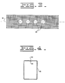
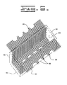
- a mold or casing as shown in phantom in Fig. 5, is used to form a header assembly 80 having a generally rectangular configuration defining a top 81, a bottom 82, a pair of sides 83 and a pair of ends 84.
- the mold in this application, has a generally rectangular configuration being formed by a bottom, a pair of ends and a pair of sides having a plurality of openings defined therein corresponding in position to the plurality of tubes 60 and the ceramic tubes 70.
- a strengthening member 86 being constructed of a ceramic woven cloth mesh has a plurality of openings 88 defined therein corresponding to the position of the plurality of tubes 60 and the ceramic tubes 70.
- the strengthening member 86 is positioned within the mold in contacting relationship with the bottom and the pair of sides and in the assembled position the plurality of openings 84 nest about the plurality of tubes 60 and the ceramic tubes 70.
- the strengthening member 86 does not overlap the ends of the mold.
- a pair of ends 89 of the strengthening member 86 extends beyond the sides of the mold a preestablished distance.
- the strengthening member 86 extends along an axis 90 generally corresponding to the axis 42 of the first ceramic member 40.
- the strengthening member 86 is a Nextel 312 Fabric, leno weave .2 tow spacing in wrap and fill direction.
- the first ceramic member 40 is positioned in the mold in spaced relationship thereto forming a void or chamber or cavity therearound.
- the spacing around the first ceramic member 40 from the mold is generally uniform or equal.
- the mold could have a generally square or possibly a cylindrical configuration.
- a reinforcement member 91 positioned within the mold and spaced from the mold and the first ceramic member 40 is a reinforcement member 91.
- the reinforcement member 91 extends along the axis 42 of the first ceramic member 40, is spaced from the first ceramic member 40 a preestablished distance and is spaced from the mold a preestablished distance. In this application, the preestablished distance from the first ceramic member 40 and the mold is equal.
- the reinforcement member 91 surrounds the first ceramic member 40 and includes a plurality of openings, not shown, therein positioned in corresponding relationship to the location of the plurality of tubes 60 and the ceramic tubes 70.
- the plurality of openings are sized to provide clearance between the reinforcement member 91, and the plurality of tubes 60 and the ceramic tubes 70.
- the reinforcement member 91 is formed from a sheet, bent into the rectangular configuration and has the ends of the sheet overlapping each other at a generally middle point on a side. The overlapping portion of the reinforcement member 91 is rigidly connected.
- the reinforcing member 91 further has a plurality of fasteners 96 attached thereto.
- the plurality of fasteners 96 are spaced apart along the axis 42 and are alternately offset one from another.
- the reinforcing member 91 is constructed from 3mm diameter stainless steel wire having a 50mm X 50mm mesh.
- the construction of the reinforcing member 91 could be that of a stainless steel expanded metal flattened mesh.
- the mesh is this application is made of stainless steel other materials such as plastic could be used.
- the essential characteristics of the reinforcement member 91 are that a portion of the reinforcement member 91 should extend substantially the entire axial length of the header assembly 80, surround the ceramic member 40 and provide openings or spaces between the extension such as are formed in a mesh.
- the reinforcement member 91 could be slightly shorter than the axial length of the header assembly 80 such as by about 12 mm, and may not totally surround the ceramic member 40, such as being of a "U" configuration being void of a complete or closed loop.
- a glue or filler, such as epoxy, not shown can be used to position the ceramic tubes 70, the plurality of tubes 60 and the reinforcing member 91 in spaced relationship to the first ceramic member 40 prior to pouring a refractory material 100 into the chamber.
- the refractory material 100 is in a slurry form and when poured into the chamber within the mold comes into contact with the strengthening member 86 and flows within the mesh portion thereof.
- the refractory material 100 nests around the first ceramic member 40, the plurality of tubes 60, the ceramic tubes 70 and within the mesh of the reinforcing member 91 filling the chamber without forming voids.
- the predetermined length of the pair of ends 89 of the strengthening material 86 extending beyond the mold are folded about the refractory material 100 to a position in which the pair of ends 89 overlap.
- a plurality of fasteners 102 as shown in Fig. 2, being made of stainless steel can be used to further attach the strengthening member 86 to the refractory material 100.
- the mold can be vibrated while the refractory material 100 is in the slurry state.
- the refractory material 100 is fiber reinforced and attaches to the strengthening member 86, the fasteners 102, the first ceramic member 40, the plurality of tubes 60, the ceramic tubes 70 and the reinforcing member 91.
- the refractory material 100 in this application, is a dense castable material having a composition by weight, of about 70% Al 2 O 3 , 25% SiO 2 , and 5% trace elements.
- One such commercially available material is sold by Babcock and Wilcox Co., New York, N.Y., under the trademark name Kaocrete 32-C. This material, as purchased is a mixture of aggregate and fine particles, the fine particles comprise about 60% of the total mixture and are defined as that portion of the mixture that will pass a no.
- the fiber reinforcement use is this application is steel fibers or whiskers which is mixed in the ratio of about 1.4 kgs of fibers to every 45.4 kgs of refractory.
- the use of high strength alloy fibers can be substituted to reduce the corrosion.
- the mold is removed and the heat exchanger 10 having the reinforcing member 91 positioned therein and the strengthening member 86 wrapped therearound is assembled and positioned within the conventional furnace or flue gas duct 11.
- the recuperator 10 includes the header assembly 80 assembled in the following manner.
- the metallic tubes 24 are positioned within the respective plurality of openings 22 within the cylindrical wall 16 of the air inlet manifold 12 and are fixedly attached to the wall 16.
- the internal surface of the inlet manifold 12 is coated with the refractory material in a conventional manner.
- strengthening member 86 is positioned within the mold along with the reinforcing member 91 positioned about the first ceramic member 40, the respective tubes 60 are inserted through corresponding ones of plurality of openings 88 in the strengthening member 86 and the plurality of openings 94 in the reinforcement member 91 and into corresponding ones of the plurality of apertures 50 in the first ceramic member 40.
- respective ceramic tubes 70 are inserted through corresponding ones of the plurality of openings 88 in the strengthening member 86 and the plurality of openings 94 in the reinforcement member 91 and into corresponding ones of the plurality of openings 52 in the first ceramic member 40.
- the threaded nut 64 with the seal 66 positioned therein is threadedly engaged onto the threaded end 62 of each of the tubes 60.
- the assembled nut 64 and sealingly position the tubes 60 about the outer surface 32 of respective tubes 24 and the nut 64 is tightened on the threaded end 62 and positions the tubes 60 relatively to the air inlet manifold 16 and the tubes 24 relatively to the ceramic tubes 70.
- the metallic ring 54 is sealingly attached to the first ceramic member 40. Glue can be added to the interface of the tubes 24 and the air inlet manifold 16, the tubes 60 and the first ceramic member 40 and the ceramic tubes 70 and the first ceramic member 40 to maintain the relative position therebetween.
- the header assembly 80 is ready to be formed.
- the refractory material 100 is poured or cast into the cavity formed by the spaced relationship of the components and the mold.
- the fiber reinforced refractory material 100 after drying fixedly attaches the components.
- the castable refractory material 100 flows into the cavity formed by the spaced relationship of the components and the mold, comes into contact with the strengthening member 86 filling the voids in the mesh, fills the spacing within the mesh of the reinforcing member 91 and contacts therewith, contacts the cylindrical wall member 44, contacts the tubes 60 and contacts the ceramic tubes 70.
- the ends 89 of the strengthening member 86 Prior to the refractory material 100 becoming hard, the ends 89 of the strengthening member 86 are extended over the refractory material 100 to a position where the ends 89 are in an overlapping position. At this point, a vibrator is attached to the mold and the refractory material 100 settles into any voids. Thus, a mechanical joint is formed which provides a high strength load bearing header assembly 80 having good thermal cycling characteristics, good resistance to a corrosive environment and good steady state strength at elevated temperatures.
- the header assembly 80 having the strengthening member 86 wrapped therearound is used with the recuperator or heat exchanger 10 which is partially disposed within the flue gas duct 11 in a conventional manner of a conventional furnace.
- the recuperator 10 within the flue gas duct 11 and the strengthening member 86 and the reinforcing member 91 aid to increase the strength of the header assembly 80 by reducing the effects of the brittleness of the refractory material 100.
- high pressure gaseous fluid or recipient fluid which in this application is air, to be heated, enters the open end 20 of the inlet manifold 12. From the inlet manifold 12, the air passes through the tubes 24 and exits the open end of each of the tubes 24.
- the air passes along the ceramic tube 70 absorbing heat from the high temperature low pressure gases or donor fluid of combustion passing through the duct 11.
- the heated air rises between the outer surfaces 32 of the tubes 24 and the ceramic tubes 70 and exits into the air outlet manifold 14.
- the heated air exits the outlet manifold 14 through the metallic ring 54 and is used in a conventional manner.
- the strengthening member 86 provides an effective reinforcement even through the more brittle refractory material 100 may crack under repeated thermal stress loading.
- the interlaced characteristics of the mesh type strengthening member 86 helps to compensate for the brittle characteristic of the refractory material 100 increasing the effective life of the header assembly 80.
Landscapes
- Engineering & Computer Science (AREA)
- Physics & Mathematics (AREA)
- Thermal Sciences (AREA)
- Mechanical Engineering (AREA)
- General Engineering & Computer Science (AREA)
- Ceramic Engineering (AREA)
- Heat-Exchange Devices With Radiators And Conduit Assemblies (AREA)
Applications Claiming Priority (2)
| Application Number | Priority Date | Filing Date | Title |
|---|---|---|---|
| US08/611,861 US5954128A (en) | 1996-03-06 | 1996-03-06 | High pressure ceramic heat exchanger |
| US611861 | 1996-03-06 |
Publications (2)
| Publication Number | Publication Date |
|---|---|
| EP0794403A2 true EP0794403A2 (fr) | 1997-09-10 |
| EP0794403A3 EP0794403A3 (fr) | 1998-08-05 |
Family
ID=24450684
Family Applications (1)
| Application Number | Title | Priority Date | Filing Date |
|---|---|---|---|
| EP97300235A Withdrawn EP0794403A3 (fr) | 1996-03-06 | 1997-01-16 | Echangeur de chaleur à haute pression en céramique |
Country Status (2)
| Country | Link |
|---|---|
| US (1) | US5954128A (fr) |
| EP (1) | EP0794403A3 (fr) |
Cited By (3)
| Publication number | Priority date | Publication date | Assignee | Title |
|---|---|---|---|---|
| EP0941759A1 (fr) * | 1998-03-12 | 1999-09-15 | Nederlandse Organisatie Voor Toegepast-Natuurwetenschappelijk Onderzoek Tno | Echangeur et son procédé de fabrication |
| US6712131B1 (en) | 1998-03-12 | 2004-03-30 | Nederlandse Organisatie Voor Toegepast - Natuurwetenschappelijk Onderzoek Tno | Method for producing an exchanger and exchanger |
| DE10331209A1 (de) * | 2003-07-10 | 2005-02-03 | Alto Deutschland Gmbh | Wärmetauscher mit Keramikboden |
Families Citing this family (8)
| Publication number | Priority date | Publication date | Assignee | Title |
|---|---|---|---|---|
| US7147050B2 (en) * | 2003-10-28 | 2006-12-12 | Capstone Turbine Corporation | Recuperator construction for a gas turbine engine |
| US7065873B2 (en) * | 2003-10-28 | 2006-06-27 | Capstone Turbine Corporation | Recuperator assembly and procedures |
| US8162040B2 (en) * | 2006-03-10 | 2012-04-24 | Spinworks, LLC | Heat exchanging insert and method for fabricating same |
| DE202009005398U1 (de) | 2009-04-08 | 2010-09-02 | Man Dwe Gmbh | Kühlsystem und Mantelreaktor mit einem solchen Kühlsystem |
| JP2012097991A (ja) * | 2010-11-04 | 2012-05-24 | Covalent Materials Corp | 熱交換器 |
| US20170219302A1 (en) * | 2014-07-29 | 2017-08-03 | Kyocera Corporation | Heat exchanger |
| US10741741B2 (en) * | 2016-06-20 | 2020-08-11 | Phononic, Inc. | Multi header for thermoelectric device |
| US10619929B2 (en) * | 2017-12-04 | 2020-04-14 | General Electric Company | Additive manufactured flow components with stress-resistant structures |
Citations (3)
| Publication number | Priority date | Publication date | Assignee | Title |
|---|---|---|---|---|
| US4642864A (en) | 1985-12-20 | 1987-02-17 | Solar Turbines Incorporated | Recuperator tube assembly |
| US4784313A (en) | 1986-03-14 | 1988-11-15 | Kernforschungsanlage Julich Gesellschaft Mit Beschrankter Haftung | Method for bonding silicon carbide molded parts together or with ceramic or metal parts |
| US5265918A (en) | 1991-11-20 | 1993-11-30 | Solar Turbines Incorporated | High pressure ceramic joint |
Family Cites Families (8)
| Publication number | Priority date | Publication date | Assignee | Title |
|---|---|---|---|---|
| US2225634A (en) * | 1938-03-04 | 1940-12-24 | Houdry Process Corp | Regulation of temperature of chemical reactions |
| US3922411A (en) * | 1958-06-02 | 1975-11-25 | Avco Corp | Honeycomb reinforced material and method of making the same |
| US4106556A (en) * | 1976-11-26 | 1978-08-15 | Thermal Transfer, Division Of Kleinewefers | Ceramic tube recuperators |
| US4269266A (en) * | 1979-08-23 | 1981-05-26 | United States Steel Corporation | Recuperator tube construction |
| US4330031A (en) * | 1979-09-12 | 1982-05-18 | Holcroft & Company | Ceramic tube recuperator |
| JPS5677692A (en) * | 1979-11-27 | 1981-06-26 | Toyo Eng Corp | Heat exchanger |
| SE461275B (sv) * | 1983-07-28 | 1990-01-29 | Mtu Muenchen Gmbh | Foerfarande foer framstaellning av varmhaallfast keramik samt enligt foerfarandet framstaelld keramikkomponent |
| DE4102909A1 (de) * | 1991-01-31 | 1992-08-06 | Man Technologie Gmbh | Werkstuecke aus faserverstaerkter keramik |
-
1996
- 1996-03-06 US US08/611,861 patent/US5954128A/en not_active Expired - Fee Related
-
1997
- 1997-01-16 EP EP97300235A patent/EP0794403A3/fr not_active Withdrawn
Patent Citations (3)
| Publication number | Priority date | Publication date | Assignee | Title |
|---|---|---|---|---|
| US4642864A (en) | 1985-12-20 | 1987-02-17 | Solar Turbines Incorporated | Recuperator tube assembly |
| US4784313A (en) | 1986-03-14 | 1988-11-15 | Kernforschungsanlage Julich Gesellschaft Mit Beschrankter Haftung | Method for bonding silicon carbide molded parts together or with ceramic or metal parts |
| US5265918A (en) | 1991-11-20 | 1993-11-30 | Solar Turbines Incorporated | High pressure ceramic joint |
Cited By (4)
| Publication number | Priority date | Publication date | Assignee | Title |
|---|---|---|---|---|
| EP0941759A1 (fr) * | 1998-03-12 | 1999-09-15 | Nederlandse Organisatie Voor Toegepast-Natuurwetenschappelijk Onderzoek Tno | Echangeur et son procédé de fabrication |
| US6174490B1 (en) | 1998-03-12 | 2001-01-16 | Nederlandse Organisatie Voor Toegepast-Natuurwetenschappelijk Onderzoek (Tno) | Method for producing an exchanger |
| US6712131B1 (en) | 1998-03-12 | 2004-03-30 | Nederlandse Organisatie Voor Toegepast - Natuurwetenschappelijk Onderzoek Tno | Method for producing an exchanger and exchanger |
| DE10331209A1 (de) * | 2003-07-10 | 2005-02-03 | Alto Deutschland Gmbh | Wärmetauscher mit Keramikboden |
Also Published As
| Publication number | Publication date |
|---|---|
| EP0794403A3 (fr) | 1998-08-05 |
| US5954128A (en) | 1999-09-21 |
Similar Documents
| Publication | Publication Date | Title |
|---|---|---|
| US5954128A (en) | High pressure ceramic heat exchanger | |
| EP1293715B1 (fr) | Procédé pour joindre des matériaux composites à matrice céramique et des métaux | |
| US4642864A (en) | Recuperator tube assembly | |
| US5687787A (en) | Fiber reinforced ceramic matrix composite internal combustion engine exhaust manifold | |
| US6464456B2 (en) | Turbine vane assembly including a low ductility vane | |
| DE60122819T2 (de) | Brennkammer mit Brennkammerwand aus Verbundwerkstoff mit keramischer Matrix | |
| US5630470A (en) | Ceramic heat exchanger system | |
| US6182442B1 (en) | Combustion chamber wall construction for high power engines and thrust nozzles | |
| CN1871488A (zh) | 尤其用于砌衬燃气轮机燃烧室壁的带有埋置在内的加强元件的陶瓷热屏砖 | |
| CA1100712A (fr) | Lamelle metal/ceramique | |
| US5881802A (en) | Refractory shield design for superheater tubes | |
| EP0190701A2 (fr) | Structure de joint pour une plaque d'extrémité et un tube | |
| US5810076A (en) | High pressure ceramic heat exchanger | |
| JP4499024B2 (ja) | アルミダイカスト用給湯管およびその製造方法 | |
| US5265918A (en) | High pressure ceramic joint | |
| US20100011776A1 (en) | Elimination of plate fins in combustion baskets by cmc insulation installed by shrink fit | |
| JPS61256194A (ja) | セラミツクチユ−ブの接続構造 | |
| JPH0144954B2 (fr) | ||
| EP1213557B1 (fr) | Structure de tubes, structure de passage de fluides et échangeur de chaleur | |
| JP3030203B2 (ja) | 高温型ラジアントチューブ | |
| JPS63243630A (ja) | ガスタ−ビン燃焼器 | |
| JPH11211375A (ja) | 熱交換器用伝熱管 | |
| MXPA98001317A (en) | Multiple ceramic reinforced with ceramic fiber, coated with me | |
| JP2001090906A (ja) | ディフューザーコーン | |
| JPH0581741B2 (fr) |
Legal Events
| Date | Code | Title | Description |
|---|---|---|---|
| PUAI | Public reference made under article 153(3) epc to a published international application that has entered the european phase |
Free format text: ORIGINAL CODE: 0009012 |
|
| AK | Designated contracting states |
Kind code of ref document: A2 Designated state(s): DE FR GB NL |
|
| PUAL | Search report despatched |
Free format text: ORIGINAL CODE: 0009013 |
|
| AK | Designated contracting states |
Kind code of ref document: A3 Designated state(s): DE FR GB NL |
|
| STAA | Information on the status of an ep patent application or granted ep patent |
Free format text: STATUS: THE APPLICATION IS DEEMED TO BE WITHDRAWN |
|
| 18D | Application deemed to be withdrawn |
Effective date: 19990206 |