EP0794422A2 - Verfahren zum Kontrollieren eines Produktes und Robot zur Durchführung des Verfahrens - Google Patents
Verfahren zum Kontrollieren eines Produktes und Robot zur Durchführung des Verfahrens Download PDFInfo
- Publication number
- EP0794422A2 EP0794422A2 EP97200641A EP97200641A EP0794422A2 EP 0794422 A2 EP0794422 A2 EP 0794422A2 EP 97200641 A EP97200641 A EP 97200641A EP 97200641 A EP97200641 A EP 97200641A EP 0794422 A2 EP0794422 A2 EP 0794422A2
- Authority
- EP
- European Patent Office
- Prior art keywords
- sample
- probe
- robot
- spectrometer
- sample holder
- Prior art date
- Legal status (The legal status is an assumption and is not a legal conclusion. Google has not performed a legal analysis and makes no representation as to the accuracy of the status listed.)
- Withdrawn
Links
- 238000000034 method Methods 0.000 title claims description 3
- 239000012467 final product Substances 0.000 title claims 2
- 239000000523 sample Substances 0.000 claims abstract description 78
- 238000005259 measurement Methods 0.000 claims abstract description 19
- 238000004458 analytical method Methods 0.000 claims abstract description 14
- 239000002184 metal Substances 0.000 claims abstract description 11
- 229910052751 metal Inorganic materials 0.000 claims abstract description 11
- 238000003556 assay Methods 0.000 claims description 6
- 239000000047 product Substances 0.000 claims 1
- 230000001680 brushing effect Effects 0.000 abstract description 6
- 229910000831 Steel Inorganic materials 0.000 description 4
- 239000010959 steel Substances 0.000 description 4
- 230000003287 optical effect Effects 0.000 description 3
- XKRFYHLGVUSROY-UHFFFAOYSA-N Argon Chemical compound [Ar] XKRFYHLGVUSROY-UHFFFAOYSA-N 0.000 description 2
- 229910052786 argon Inorganic materials 0.000 description 1
- QVGXLLKOCUKJST-UHFFFAOYSA-N atomic oxygen Chemical compound [O] QVGXLLKOCUKJST-UHFFFAOYSA-N 0.000 description 1
- 238000005097 cold rolling Methods 0.000 description 1
- 238000011109 contamination Methods 0.000 description 1
- 239000007789 gas Substances 0.000 description 1
- 238000005098 hot rolling Methods 0.000 description 1
- 238000004519 manufacturing process Methods 0.000 description 1
- 239000000463 material Substances 0.000 description 1
- 239000000155 melt Substances 0.000 description 1
- 150000002739 metals Chemical class 0.000 description 1
- 238000012986 modification Methods 0.000 description 1
- 230000004048 modification Effects 0.000 description 1
- 239000001301 oxygen Substances 0.000 description 1
- 229910052760 oxygen Inorganic materials 0.000 description 1
- 238000001228 spectrum Methods 0.000 description 1
Images

Classifications
-
- G—PHYSICS
- G01—MEASURING; TESTING
- G01N—INVESTIGATING OR ANALYSING MATERIALS BY DETERMINING THEIR CHEMICAL OR PHYSICAL PROPERTIES
- G01N21/00—Investigating or analysing materials by the use of optical means, i.e. using sub-millimetre waves, infrared, visible or ultraviolet light
- G01N21/62—Systems in which the material investigated is excited whereby it emits light or causes a change in wavelength of the incident light
- G01N21/66—Systems in which the material investigated is excited whereby it emits light or causes a change in wavelength of the incident light electrically excited, e.g. electroluminescence
- G01N21/67—Systems in which the material investigated is excited whereby it emits light or causes a change in wavelength of the incident light electrically excited, e.g. electroluminescence using electric arcs or discharges
-
- G—PHYSICS
- G01—MEASURING; TESTING
- G01N—INVESTIGATING OR ANALYSING MATERIALS BY DETERMINING THEIR CHEMICAL OR PHYSICAL PROPERTIES
- G01N1/00—Sampling; Preparing specimens for investigation
- G01N1/28—Preparing specimens for investigation including physical details of (bio-)chemical methods covered elsewhere, e.g. G01N33/50, C12Q
- G01N1/286—Preparing specimens for investigation including physical details of (bio-)chemical methods covered elsewhere, e.g. G01N33/50, C12Q involving mechanical work, e.g. chopping, disintegrating, compacting, homogenising
-
- G—PHYSICS
- G01—MEASURING; TESTING
- G01N—INVESTIGATING OR ANALYSING MATERIALS BY DETERMINING THEIR CHEMICAL OR PHYSICAL PROPERTIES
- G01N1/00—Sampling; Preparing specimens for investigation
- G01N1/28—Preparing specimens for investigation including physical details of (bio-)chemical methods covered elsewhere, e.g. G01N33/50, C12Q
- G01N1/32—Polishing; Etching
-
- G—PHYSICS
- G01—MEASURING; TESTING
- G01N—INVESTIGATING OR ANALYSING MATERIALS BY DETERMINING THEIR CHEMICAL OR PHYSICAL PROPERTIES
- G01N33/00—Investigating or analysing materials by specific methods not covered by groups G01N1/00 - G01N31/00
- G01N33/20—Metals
- G01N33/202—Constituents thereof
- G01N33/2028—Metallic constituents
-
- G—PHYSICS
- G01—MEASURING; TESTING
- G01N—INVESTIGATING OR ANALYSING MATERIALS BY DETERMINING THEIR CHEMICAL OR PHYSICAL PROPERTIES
- G01N35/00—Automatic analysis not limited to methods or materials provided for in any single one of groups G01N1/00 - G01N33/00; Handling materials therefor
- G01N35/0099—Automatic analysis not limited to methods or materials provided for in any single one of groups G01N1/00 - G01N33/00; Handling materials therefor comprising robots or similar manipulators
Definitions
- the present invention relates to a robot for spectrometric analysis of metal samples and to a method for carrying out final control of metal products.
- the objective of the present invention is to simplify analysis measurement of metal samples, to make it more reliable and to make a mix-up check simple and reliable.
- the spectrometer shown in the drawing is identified generally by the reference numeral 12, with an assay probe 13.
- the spectrometer can be of type SPECTROTEST Jr which is an optical emission spectrometer (OES).
- OES optical emission spectrometer
- the assay probe melts by sparking a small amount of metal in the sample, and the light is transferred through an optical cable 14 to the spectrometer 12 where the intensities for the spectra of different metals are analysed and translated to metal contents. It is possible to program the analysis limits of the different steel grades so that a signal indicating an accepted or unaccepted measurement is obtained.
- the robot has a fixed frame of which only a pair of guides 16 is shown.
- a movable frame 17 is mounted on the guiders 16. Only the bottom plate 18 of the movable frame 17 is shown with sliding components 19, 20 on the guiders 16 and a back wall 21.
- a compressed-air cylinder 22 is connected to slide the movable frame 17 along the guiders 16 of the fixed frame.
- a sample holder 25 is mounted onto the fixed frame. It has a compressed-air cylinder 26 with a plate 27 with which it holds the sheet-metal sample 28 in place.
- a brushing machine 30 is also on the fixed frame, it has an axially rotating brush 31 and a compressed-air cylinder 32 the piston rod of which carries a plate 33.
- the movable frame 17 has a guider 35 on which a carriage 36 for the assay probe 13 is mounted.
- a compressed-air cylinder 37 is connected to advance the probe carriage 36 along the guider 35.
- a grinding machine 40 is mounted on a guider 39 which is also supported by the movable frame 17. It can be advanced along the guider 39 by a compressed-air cylinder 42.
- the grinding machine 40 has a rotating grinding wheel 41 with loose radial grinding belts which give a relatively large grinding surface.
- the guiders 35 and 39 are in parallel with each other but perpendicular to the guiders 16 of the fixed frame. Two compressed-air cylinders are mounted onto the movable frame 17 parallel to each other so that only one of them 45 can be seen in the figure.
- stop lug 46 which, when the piston rod is projected as in the figure, is in position to stop against a cross bar 47 attached between the guider pair 16 of the fixed frame.
- the lug 48 on the other cylinder can be seen in the figure where it is shown in non-operative position.
- the lugs 46, 48 are different sizes so that they will define two different stop positions for the movement to the right of the movable frame 17 in the figure. When both lugs 46, 48 are in their non-operative positions, the bottom plate 18 will rest against the cross bar 47 which gives a third stop position.
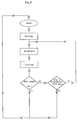
- FIG. 2 is a flow chart showing the sequences in a measurement operation and such a measurement operation shall now be described.
- the steering system for sequential control is of a conventional type and is therefore not shown.
- Figure 1 the robot is shown in its idle position, in which the probe 13 is in line with the brushing machine 30 and the grinding wheel 41 is directly in front of the sample holder 25.
- the probe 13 is moved towards the plate 33 so that the working surface of the probe is protected and the grinding machine 40 is in a retired idle position.
- a measurement sequence begins when the operator puts a sheet-metal sample 28 into the sample holder 25 and adjusts the spectrometer for the correct steel grade.
- the cylinder 26 clamps the sheet sample 28 and the grinding machine 40 starts and is brought upwards by the cylinder 42 so that the grinding wheel 41 grinds smooth an approximately square area on the sheet sample 28.
- the grinding machine 40 goes down again as the probe carriage 36 also goes down.
- the cylinder 22 then advances the movable frame 17 to the right until the stop lug 46 of the cylinder 45 stops against the cross bar 47. In this relative position between the fixed frame 16 and the movable frame 17, the probe 13 is in front of the sheet sample 28 and is brought up against the sheet sample and begins sparking.
- the spectrometer 12 gives a clear signal and initiates release of the sheet sample 28 and the return of the movable frame 17 to the initial position shown in the figure.
- the cylinder 32 has withdrawn its plate 33 and the probe 13 is brought up against the brushing machine which is started and brushes clean the top surface of the probe so that it is clean before the next measurement and does not itself add contamination.
- the cylinder 32 brings the plate 33 forth when the probe 13 has gone down and thereafter the probe goes up again to bear on the plate 33 where the top surface of the probe is protected.
- Shrouding gas e.g. argon is introduced through a hose which lies within the same casing as the optical cable, in a low continuous flow towards the top surface of the probe and protects it from atmospheric oxygen.
- the probe does not go up into the idle position but the movable frame 17 is advanced to the right in the figure to a second measurement position.
- the cylinder 45 first pulls up the stop lug 46 and the next cylinder brings down another stop lug 48 so that the frame 17 comes to an operative position somewhat more than 1 cm to the side of the previous operative position. In this way the probe 13 can make a new measurement on a clean surface right beside the area where it took the first measurement.
- the robot repeats the measurement one more time; this time with both stop lugs 46, 48 in non-operative positions. If the third measurement is also unaccepted, the robot stops in idle position with the sheet sample 28 in grip. The operator must therefore give an extra command so that the sheet sample can be released, and he can therefore not avoid noticing that the sample is not accepted, which increases the reliability.
- both the brushing machine 30 and sample holder 25 are fixed while the probe carriage 36 and grinding machine 40 are movable.
- the different power units have been described as compressed-air cylinders, but they can be other types of power units.
Landscapes
- Health & Medical Sciences (AREA)
- Physics & Mathematics (AREA)
- Life Sciences & Earth Sciences (AREA)
- Chemical & Material Sciences (AREA)
- Analytical Chemistry (AREA)
- Biochemistry (AREA)
- General Health & Medical Sciences (AREA)
- General Physics & Mathematics (AREA)
- Immunology (AREA)
- Pathology (AREA)
- Nuclear Medicine, Radiotherapy & Molecular Imaging (AREA)
- Sampling And Sample Adjustment (AREA)
Applications Claiming Priority (2)
| Application Number | Priority Date | Filing Date | Title |
|---|---|---|---|
| SE9600858 | 1996-03-06 | ||
| SE9600858A SE515080C2 (sv) | 1996-03-06 | 1996-03-06 | Robot för spektrometeranalysering av metallprover och ett sätt att utföra leveranskontroll av metalliska produkter |
Publications (2)
| Publication Number | Publication Date |
|---|---|
| EP0794422A2 true EP0794422A2 (de) | 1997-09-10 |
| EP0794422A3 EP0794422A3 (de) | 1998-07-08 |
Family
ID=20401676
Family Applications (1)
| Application Number | Title | Priority Date | Filing Date |
|---|---|---|---|
| EP97200641A Withdrawn EP0794422A3 (de) | 1996-03-06 | 1997-03-04 | Verfahren zum Kontrollieren eines Produktes und Robot zur Durchführung des Verfahrens |
Country Status (2)
| Country | Link |
|---|---|
| EP (1) | EP0794422A3 (de) |
| SE (1) | SE515080C2 (de) |
Cited By (2)
| Publication number | Priority date | Publication date | Assignee | Title |
|---|---|---|---|---|
| EP0988908A1 (de) * | 1998-09-22 | 2000-03-29 | KM Europa Metal AG | Verfahren zur Lokalisierung von Elementkonzentrationen in einem Gussstrang und Anordnung zur Durchführung des Verfahrens |
| CN113252927A (zh) * | 2021-06-17 | 2021-08-13 | 上海美诺福科技股份有限公司 | 光谱自动上样机 |
Families Citing this family (2)
| Publication number | Priority date | Publication date | Assignee | Title |
|---|---|---|---|---|
| CN108801724B (zh) * | 2018-03-26 | 2021-09-24 | 翟如扬 | 一种污水污染物检验用样品处理装置 |
| CN118408774B (zh) * | 2024-04-28 | 2024-10-29 | 青岛海洋地质研究所 | 一种基于水下机器人的海洋地质勘查用钻探设备及方法 |
Family Cites Families (6)
| Publication number | Priority date | Publication date | Assignee | Title |
|---|---|---|---|---|
| JPS6038657B2 (ja) * | 1980-08-25 | 1985-09-02 | マツダ株式会社 | 分光分析方法 |
| DE3344944C2 (de) * | 1983-12-13 | 1986-06-05 | Knieps & Pöckler, 5828 Ennepetal | Verfahren zur Analyse von Stahl während seiner Herstellung und Weiterverarbeitung |
| US4641968A (en) * | 1984-12-17 | 1987-02-10 | Baird Corporation | Mobile spectrometric apparatus |
| DE4103059A1 (de) * | 1991-02-01 | 1992-08-13 | Gutehoffnungshuette Man | Metallurgisches, vollautomatisch arbeitendes labor |
| JPH07225188A (ja) * | 1994-02-15 | 1995-08-22 | Sumitomo Metal Ind Ltd | 発光分光分析方法 |
| DE4413090C2 (de) * | 1994-04-15 | 1999-08-12 | Herzog Maschinenfabrik Gmbh & | Probenvorbereitungsmaschine |
-
1996
- 1996-03-06 SE SE9600858A patent/SE515080C2/sv not_active IP Right Cessation
-
1997
- 1997-03-04 EP EP97200641A patent/EP0794422A3/de not_active Withdrawn
Cited By (4)
| Publication number | Priority date | Publication date | Assignee | Title |
|---|---|---|---|---|
| EP0988908A1 (de) * | 1998-09-22 | 2000-03-29 | KM Europa Metal AG | Verfahren zur Lokalisierung von Elementkonzentrationen in einem Gussstrang und Anordnung zur Durchführung des Verfahrens |
| US6411379B1 (en) * | 1998-09-22 | 2002-06-25 | Km Europa Metal Ag | Method and apparatus for the localization of element concentrations in a continuous casting |
| KR100681803B1 (ko) * | 1998-09-22 | 2007-02-15 | 카엠 오이로파 메탈 악티엔 게젤샤프트 | 연속 주조물에서의 원소 농도 집중부를 국소진단하는 장치 |
| CN113252927A (zh) * | 2021-06-17 | 2021-08-13 | 上海美诺福科技股份有限公司 | 光谱自动上样机 |
Also Published As
| Publication number | Publication date |
|---|---|
| EP0794422A3 (de) | 1998-07-08 |
| SE9600858L (sv) | 1997-09-07 |
| SE515080C2 (sv) | 2001-06-05 |
| SE9600858D0 (sv) | 1996-03-06 |
Similar Documents
| Publication | Publication Date | Title |
|---|---|---|
| US4794221A (en) | Apparatus and method for exchanging electrode chips used for resistance welding | |
| US4084752A (en) | Gap adjusting system for crusher and method | |
| KR100536118B1 (ko) | 연속 주조된 재료의 표면 결함을 연속적으로 기계적인 가공에 의해 제거하기 위하여 표면의 결함을 자동으로 검출하는 방법 및 장치 | |
| US4509295A (en) | Controlled grinding of rollers for elimination of cracks | |
| EP0154319A2 (de) | Walzenschleifvorrichtung für Walzwerke | |
| EP0794422A2 (de) | Verfahren zum Kontrollieren eines Produktes und Robot zur Durchführung des Verfahrens | |
| US4388722A (en) | Automatic cleaning device for use in an extracting furnace of an apparatus for analyzing gases in metals | |
| EP0591128A1 (de) | Vorrichtung und verfahren zum schneiden von segmenten von blocken | |
| US3839829A (en) | Machine tool fault indicator | |
| CN111251092A (zh) | 一种铝合金棒材的同轴度校准加工设备及工作方法 | |
| CN113000729B (zh) | 燃烧试验专用整直裁线机 | |
| JPH05154516A (ja) | 圧延ロールのオンラインプロフィル測定法および装置 | |
| JPH06114706A (ja) | 管内ビードの研削装置 | |
| CN212443020U (zh) | 一种五金制品的自动测量剪切设备 | |
| JP2984772B2 (ja) | プレス入側材料測長方法並びに測長装置およびプレス入側材料供給装置 | |
| KR100554744B1 (ko) | 압연코일 시편 채취장치 | |
| JPH06335848A (ja) | センタレス研磨機のワーク供給装置、同ワーク排出装置及びこれらを用いた研磨装置 | |
| US5455990A (en) | Device for cleaning Morel cylinders on a card | |
| KR200262008Y1 (ko) | 자동시료연마장치 | |
| CN219104428U (zh) | 一种钢水取样测温装置 | |
| CN116590508B (zh) | 一种汽车刹车盘用的热处理设备 | |
| SU804248A1 (ru) | Лини резки труб | |
| JPH07318495A (ja) | 発光分光分析装置用試料自動回転装置 | |
| KR970006493Y1 (ko) | 철강재 절단용 원형톱날 검사장치 | |
| CN113878275B (zh) | 一种端盖焊接机构 |
Legal Events
| Date | Code | Title | Description |
|---|---|---|---|
| PUAI | Public reference made under article 153(3) epc to a published international application that has entered the european phase |
Free format text: ORIGINAL CODE: 0009012 |
|
| AK | Designated contracting states |
Kind code of ref document: A2 Designated state(s): DE ES FI FR GB IT |
|
| PUAL | Search report despatched |
Free format text: ORIGINAL CODE: 0009013 |
|
| AK | Designated contracting states |
Kind code of ref document: A3 Designated state(s): DE ES FI FR GB IT |
|
| 17P | Request for examination filed |
Effective date: 19981126 |
|
| RAP1 | Party data changed (applicant data changed or rights of an application transferred) |
Owner name: AVESTAPOLARIT AB |
|
| 17Q | First examination report despatched |
Effective date: 20030523 |
|
| GRAP | Despatch of communication of intention to grant a patent |
Free format text: ORIGINAL CODE: EPIDOSNIGR1 |
|
| STAA | Information on the status of an ep patent application or granted ep patent |
Free format text: STATUS: THE APPLICATION IS DEEMED TO BE WITHDRAWN |
|
| 18D | Application deemed to be withdrawn |
Effective date: 20040311 |