EP0795414A2 - Bildaufzeichnungsgerät versehen mit einer Vorrichtung zum Entfernen von Ladungen von dem Aufzeichnungsträger - Google Patents
Bildaufzeichnungsgerät versehen mit einer Vorrichtung zum Entfernen von Ladungen von dem Aufzeichnungsträger Download PDFInfo
- Publication number
- EP0795414A2 EP0795414A2 EP97301723A EP97301723A EP0795414A2 EP 0795414 A2 EP0795414 A2 EP 0795414A2 EP 97301723 A EP97301723 A EP 97301723A EP 97301723 A EP97301723 A EP 97301723A EP 0795414 A2 EP0795414 A2 EP 0795414A2
- Authority
- EP
- European Patent Office
- Prior art keywords
- recording medium
- ink
- recording apparatus
- eject
- image
- Prior art date
- Legal status (The legal status is an assumption and is not a legal conclusion. Google has not performed a legal analysis and makes no representation as to the accuracy of the status listed.)
- Withdrawn
Links
Images





Classifications
-
- B—PERFORMING OPERATIONS; TRANSPORTING
- B41—PRINTING; LINING MACHINES; TYPEWRITERS; STAMPS
- B41J—TYPEWRITERS; SELECTIVE PRINTING MECHANISMS, i.e. MECHANISMS PRINTING OTHERWISE THAN FROM A FORME; CORRECTION OF TYPOGRAPHICAL ERRORS
- B41J2/00—Typewriters or selective printing mechanisms characterised by the printing or marking process for which they are designed
- B41J2/005—Typewriters or selective printing mechanisms characterised by the printing or marking process for which they are designed characterised by bringing liquid or particles selectively into contact with a printing material
- B41J2/01—Ink jet
- B41J2/015—Ink jet characterised by the jet generation process
- B41J2/04—Ink jet characterised by the jet generation process generating single droplets or particles on demand
- B41J2/06—Ink jet characterised by the jet generation process generating single droplets or particles on demand by electric or magnetic field
-
- B—PERFORMING OPERATIONS; TRANSPORTING
- B41—PRINTING; LINING MACHINES; TYPEWRITERS; STAMPS
- B41J—TYPEWRITERS; SELECTIVE PRINTING MECHANISMS, i.e. MECHANISMS PRINTING OTHERWISE THAN FROM A FORME; CORRECTION OF TYPOGRAPHICAL ERRORS
- B41J11/00—Devices or arrangements of selective printing mechanisms, e.g. ink-jet printers or thermal printers, for supporting or handling copy material in sheet or web form
- B41J11/0015—Devices or arrangements of selective printing mechanisms, e.g. ink-jet printers or thermal printers, for supporting or handling copy material in sheet or web form for treating before, during or after printing or for uniform coating or laminating the copy material before or after printing
-
- B—PERFORMING OPERATIONS; TRANSPORTING
- B41—PRINTING; LINING MACHINES; TYPEWRITERS; STAMPS
- B41J—TYPEWRITERS; SELECTIVE PRINTING MECHANISMS, i.e. MECHANISMS PRINTING OTHERWISE THAN FROM A FORME; CORRECTION OF TYPOGRAPHICAL ERRORS
- B41J29/00—Details of, or accessories for, typewriters or selective printing mechanisms not otherwise provided for
-
- B—PERFORMING OPERATIONS; TRANSPORTING
- B41—PRINTING; LINING MACHINES; TYPEWRITERS; STAMPS
- B41J—TYPEWRITERS; SELECTIVE PRINTING MECHANISMS, i.e. MECHANISMS PRINTING OTHERWISE THAN FROM A FORME; CORRECTION OF TYPOGRAPHICAL ERRORS
- B41J2/00—Typewriters or selective printing mechanisms characterised by the printing or marking process for which they are designed
- B41J2/005—Typewriters or selective printing mechanisms characterised by the printing or marking process for which they are designed characterised by bringing liquid or particles selectively into contact with a printing material
- B41J2/01—Ink jet
- B41J2/015—Ink jet characterised by the jet generation process
- B41J2/04—Ink jet characterised by the jet generation process generating single droplets or particles on demand
- B41J2/06—Ink jet characterised by the jet generation process generating single droplets or particles on demand by electric or magnetic field
- B41J2002/061—Ejection by electric field of ink or of toner particles contained in ink
Definitions
- the present invention relates to an image recording apparatus such as a copying machine, a facsimile, a printer, and the like. Particularly, the present invention relates to an image recording apparatus that ejects ink intermittently by controlling charged vaporous ink with an electric field to have ink adhere onto or permeate into the recording medium selectively to form an image.
- the Applicant discloses in U.S. Patent Application Number 08/612,339 an image recording method and apparatus that ejects vaporous ink intermittently according to a signal corresponding to image data to be recorded to have the ink adhere onto or permeate into the recording medium to obtain an image.
- An image recording apparatus includes a print head unit 1, a recording medium 12, and a back electrode 11.
- Print head unit 1 includes a heater device 2, a charging electrode 4, an electrostatic shutter 8, and a control unit 9.
- Heater device 2 includes vaporizing heater 13.
- Electrostatic shutter 8 includes a common electrode 8A and a control electrode 8B provided in a comb-like manner at the interval of 169 ⁇ m corresponding to the recording density. Common electrode 8A is grounded.
- Powder ink 3 is stored within print head unit 1.
- Print head unit 1 includes heater device 2 formed of heater 13 for heating and converting powder ink 3 into vaporous ink 3G and a heat radiation plate not shown, and a thin wire electrode of 50-100 ⁇ m in diameter which is charge electrode 4 for charging vaporous ink 3G.
- a plurality of eject holes 14 through which ink 3G is sprayed out are formed at the upper portion of print heat unit 1.
- Electrostatic shutter 8 is provided at both sides of eject holes 14.
- the plurality of eject holes 14 are formed along a length corresponding to the print width.
- the distance between each eject hole 14 is set according to the recording density. For example, the distance is 200 ⁇ m when the recording density is 150dpi.
- the colorant includes anthoraisothiazole type, quinophthalone type, pyrazolone type, pyridoneazo type, styryl type, and the like for yellow.
- magenta anthraquinone type, dicyanoimidazole type, thiadiazoleazo type, tricyanovinyl type, and the like are used.
- cyan azo type, anthraquinone type, naphthoquinone type, and indoaniline type and the like are used.
- Powder ink 3 is vaporized to be cunverted into vaporous ink 3G.
- a voltage of +2 to 5kV is applied to charge electrode 4
- corona discharge occurs from charge electrode 4 towards heater device 2 that is grounded.
- vaporous ink 3G is charged with plus ions.
- Recording medium 12 is carried by a transport device 22 in the direction of arrow Al to arrive at a position facing eject hole 14.
- a minus voltage of -0.5 to -2kV is applied to back electrode 11 provided at the back surface side of the printing face of recording medium 12, the charged vaporous ink 3G is attracted towards recording medium 12.
- control electrode 8B When the voltage of control electrode 8B attains 500V (H), for example, electrostatic shutter 8 is turned on. More specifically, an electric field is generated from control electrode 8B towards common electrode 8A. Therefore, gaseous ink 3G positively charged cannot pass through electrostatic shutter 8. In contrast, when the voltage of control electrode 8B attains 0V (L), no electric field is generated between control electrode 8B and common electrode 8A. In other words, electrostatic shutter 8 is OFF. Therefore, ink 3G is attracted by the electric field of back electrode 11 to pass through electrostatic shutter 8.
- H 500V
- electrostatic shutter 8 When the voltage of control electrode 8B attains 500V (H), for example, electrostatic shutter 8 is turned on. More specifically, an electric field is generated from control electrode 8B towards common electrode 8A. Therefore, gaseous ink 3G positively charged cannot pass through electrostatic shutter 8. In contrast, when the voltage of control electrode 8B attains 0V (L), no electric field is generated between control electrode 8B and common electrode 8A. In other words, electrostatic shutter
- ejection of ink can be controlled in an intermittent manner by altering the voltage applied to electrostatic shutter 8. Also, by controlling the application of voltage to electrostatic shutter 8 corresponding to each pixel, the passage of vaporous ink 3G can be controlled on a pixel-by-pixel basis.
- a print head unit 1A has an eject hole 14A formed in a slit configuration.
- Electrostatic shutter 8 is provided at both of the longer sides of eject hole 14A. Similar to the case of Fig. 2, electrostatic shutter 8 includes common electrode 8A and control electrodes 8B provided in a comb-like manner at an interval of 169 ⁇ m corresponding to the recording density. Common electrode 8A is grounded.
- the length of eject hole 14A is set corresponding to the print width in a line head. For example, the length of eject hole 14A is approximately 200mm with a print width of A4 in size and approximately 140mm with the print width of A5 in size.
- the width of eject hole 14A is set according to the recording density.
- the width of eject hole 14A is 200 ⁇ m when the recording density is 150dpi.
- the eject hole formed in a slit configuration is advantageous over eject holes 14 formed as shown in Fig. 2 in that clogging does not easily occur.
- Print head 1B has a plurality of eject holes 14B formed of an annular configuration.
- An electrostatic shutter 81 is provided at the upper and lower portions of eject hole 14B.
- the plurality of eject holes 14B is formed of a length corresponding to the print width. The length is approximately 200mm for a print width of A4 in size and approximately 140mm for a print width of A5 in size.
- the respective pitch of eject hole 14B is set according to the recording density. For example, the pitch is 169 ⁇ m when the recording density is 150dpi.
- Each electrostatic shutter 81 includes annular electrodes 8B1 and 8A1 formed at the upper and lower portions of eject hole 14B. Electrode 8A1 is grounded. The other electrode 8B1 is connected to a power source of high voltage.
- the above-described image recording apparatus controls ejection of the charged vaporous ink by controlling the electric field.
- ejection of the charged vaporous ink cannot be controlled.
- the recording medium may be charged when forwarded by a transport device such as a roller.
- a transport device such as a roller.
- the location of the charged vaporous ink on the recording medium is offset if the recording medium is charged. As a result, there is a problem that the picture quality of the recording image is degraded.
- An object of the present invention is to provide an image recording apparatus that can record an image of high accuracy.
- Another object of the present invention is to provide an image recording apparatus that has ejected charged ink hit a predetermined position accurately on a recording medium to adhere onto or permeate into the recording medium.
- a further object of the present invention is to provide an image recording apparatus that can always have ejected charged ink sprayed out from an eject hole towards a predetermined direction of a recording medium side.
- Still another object of the present invention is to provide an image recording apparatus that can maintain at a predetermined state an electric field by an electrostatic shutter and a back electrode to eject charged ink.
- Yet another object of the present invention is to provide an image recording apparatus that can remove charge of a recording medium which becomes a cause of disturbing the state of an electric field for ejecting charged ink.
- an image recording apparatus includes a transport unit for conveying a recording medium, and a print head.
- the print head includes a heater unit for heating and vaporizing ink, an eject unit for ejecting ink vaporized by the heater unit onto a recording medium, and an eject control unit for controlling the eject unit so that vaporous ink is ejected intermittently according to image data corresponding to an image to be recorded.
- the eject unit includes a charging unit for charging vaporous ink, and a back electrode unit provided at the backside of the recording medium for attracting vaporous ink charged by the charging unit onto the recording medium.
- the eject control unit includes an electrostatic shutter unit for controlling ejection of the vaporous ink charged by the charging unit with an electric field.
- the image recording apparatus further includes a discharger provided upstream of the eject unit in the conveying direction of the recording medium for removing charges of the recording medium.
- the discharger unit preferably includes a first discharger device provided at the recording face side of the recording medium and a second discharger device provided at the back surface side of the recording medium.
- Each of the first and second discharger devices can include a contact unit provided at a position forming contact with the recording medium.
- the contact unit is formed of a conductive material.
- the contact unit is grounded.
- the heater unit heats and vaporizes ink.
- the charging unit charges the vaporous ink.
- the transportation unit initiates transportation of the recording medium.
- the contact of the recording medium with the discharger unit causes the charges present on the surface of the recording medium to be removed.
- ejection of the charged vaporous ink onto the recording medium is controlled by the electric field of the electrostatic shutter unit.
- the vaporous ink is ejected towards the recording medium having the charges removed by the discharger unit.
- the electric field for controlling ejection of vaporous ink is maintained at a predetermined state without being affected by the charge on the recording medium. Therefore, the ejected vaporous ink is accurately sprayed out from the eject hole to a predetermined direction to accurately hit a predetermined position on the recording medium.
- the ink adheres onto or permeates into the recording medium. As a result, an image recording apparatus that can record a fine image can be provided.
- an image recording apparatus includes a transport unit for conveying a recording medium, and a print head.
- the print head includes a heater unit for heating and vaporizing ink, an eject unit for ejecting ink vaporized by the heater unit onto a recording medium, and an eject control unit for controlling the eject unit so that vaporous ink is discharged intermittently according to image data corresponding to an image to be recorded.
- the eject unit includes a charging unit for charging vaporous ink, and a back electrode unit provided at the backside of the recording medium for attracting vaporous ink charged by the charger unit onto the recording medium.
- the eject control unit includes an electrostatic shutter unit for controlling ejection of vaporous ink charged by the charging unit with an electric field.
- the transport unit includes a pair of rollers provided upstream of the eject unit in the conveyed direction of the recording medium, extending in the width direction of the recording medium so as to sandwich the recording medium.
- the roller of the pair of rollers provided at the recording face side of the recording medium is formed of a conductive material, and grounded.
- the recording medium By bringing the recording medium in contact with the roller formed of a conductive material, the charges present on the surface of the recording medium in contact with the roller are removed.
- the recording medium is conveyed to arrive at the eject unit of the print head, ejection of the charged vaporous ink towards the recording medium is controlled by the electric field of the electrostatic shutter unit.
- Vaporous ink is ejected towards the surface of the recording medium having the charges removed by the roller formed of a conductive material.
- the electric field for controlling ejection of vaporous ink is maintained at a predetermined state without being affected by the charges on the recording medium. Therefore, the ejected vaporous ink is accurately sprayed out from the eject hole in a predetermined direction to accurately hit a predetermined position on the recording medium.
- the ink adheres onto or permeates into the recording medium. As a result, an image recording apparatus that can record a fine image is provided.
- Fig. 1 is a sectional view showing an entire structure of an image recording apparatus according to related art.
- Figs. 2, 3A and 3B are perspective sectional views of a structure of an electrostatic shutter unit.
- Fig. 4 is a sectional view showing an entire structure of an image recording apparatus according to a first embodiment of the present invention.
- Fig. 5 is a perspective view of main components of the image recording apparatus according to the first embodiment.
- Figs. 6A - 6H show the timing of the operation of the image recording apparatus of the first embodiment.
- Figs. 7A - 7C are diagrams for describing a circuit detecting the beginning of a recording medium in the image recording apparatus of the first embodiment.
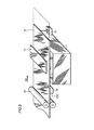
- Figs. 8 and 9 are perspective view of main components of an image recording apparatus according to a second embodiment.
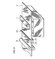
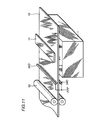
- Figs. 10 and 11 are perspective views of main components of an image recording apparatus according to a third embodiment.
- Fig. 12 is a perspective view of main components of an image recording apparatus according to a fourth embodiment.
- FIG. 4 An image recording apparatus of the first embodiment will be described hereinafter with reference to Figs. 4 and 5. Components identical to those of the above-described image recording apparatus have the same reference characters allotted, and detailed description thereof will not be repeated here.
- the direction at right angles to the drawing sheet is referred to as the X axis
- the horizontal direction on the drawing sheet perpendicular to the X axis is referred to as the Y axis
- the vertical direction on the drawing sheet crossing the X and Y axes at right angles is referred to the Z axis.
- the image recording apparatus of the first embodiment includes a print head unit 1 for recording an image on a recording medium 12, a transport device 22 for conveying the recording medium to print head unit 1, a discharger device 24 provided upstream of print head unit 1 in the conveying direction of recording medium 12 for removing the charges on recording medium 12, and a photo interrupter 23 provided downstream of print head unit 1 in the conveying direction of recording medium 12 for detecting a leading edge of recording medium 12.
- Print head unit 1 includes a heater device 2 provided at the bottom of print head unit 1 for heating powder ink 3 into vaporous ink 3G, a charging electrode 4 provided inside print head unit 1 for charging vaporous ink 3G, a back electrode unit 11 at the backside of recording medium 12 for attracting vaporous ink 3G charged by charging electrode 4 onto recording medium 12, and an electrostatic shutter 8 provided in the proximity of an eject hole 14 formed at the upper portion of print head unit 1 for controlling ejection of vaporous ink 3G by an electric field.
- Powder ink 3 is stored within print head unit 1.
- Heater device 2 for heating and vaporizing powder ink 3 is provided at the bottom portion of print head unit 1. Heater device 2 is controlled by a heating control device. The interior of print head unit 1 is gradually filled with vaporous ink 3G when powder ink 3 is heated by heater device 2.
- a thin wire electrode of 50 to 100 ⁇ m in diameter which is a charging electrode 4 is provided in the X axis direction.
- Charging electrode 4 is connected to a power source.
- a voltage of +2 to +5kV is applied to charging electrode 4.
- Vaporous ink 3G is charged positively by charging electrode 4.
- a plurality of eject holes 14 at an interval according to the resolution and electrostatic shutter 8 are provided in the X axis direction at the upper portion of print head unit 1.
- one eject hole of a slit configuration and electrostatic shutters at both sides thereof may be provided.
- an annular eject hole and an annular electrostatic shutter may be provided.
- Back electrode 11 is provided in the X axis direction at the backside of recording medium 12. A minus voltage of -0.5 to -2kV is applied to back electrode 11 from the power supply.
- Discharger device 24 is provided between one pair of rollers which is transportation device 22 and print head unit 1. Referring to Figs. 4 and 5, discharger device 24 is provided extending in the X axis direction so as to form contact with the printing face of recording medium 12. Although the width of discharger device 24, i.e. the length in the X axis direction, is illustrated to be substantially equal to the width of recording medium 12, the present invention is not limited to this length. It may be made greater than the width of recording medium 12. Discharger device 24 is formed of a conductive member such as metal, conductive rubber, or conductive resin. Discharger device 24 is grounded.
- Recording medium 12 is conveyed in the direction of arrow A2 by transport device 22. Recording medium 12 passing through transport device 22 is brought into contact with discharger device 24 prior to arriving at print head unit 1. Discharger device 24 is grounded. The charges, if any, present on recording medium 12 at the area in contact with discharger device 24 are removed by discharger device 24 and the ground line. Therefore, recording medium 12 is electrically neutral when arriving at print head unit 1. Therefore, the spray out of the charged vaporous ink 3G will not be disturbed.
- the CPU of the image recording apparatus provides a print operation signal to the heating control device at time TA.
- the print operation signal indicates that the image recording apparatus attains a standby state when at an L level and an operational state at an H level.
- This print operation signal provides the timing of initiating a printout operation at its rising edge and the timing of terminating a print out operation at its falling edge.
- Heater device 2 is driven at time TB, triggered at the rise of the print operation signal at time TA.
- a voltage of +2 to 5kV is applied to charging electrode 4.
- Powder ink 3 is heated when heater device 2 is driven.
- the temperature of powder ink 3 becomes higher than the sublimation temperature of TG, powder ink 3 is vaporized into ink 3G.
- the amount of vaporous ink 3G increases over time.
- the threshold value is reached at time TC.
- the threshold value is the amount of vaporous ink adequate for ejection.
- the printer enters a print enable state when the amount of vaporous ink exceeds the threshold value.
- Vaporous ink 3G is charged positively by the corona discharge of charging electrode 4.
- Heater device 2 is controlled by the heating control device so that the interior of print head unit 1 is maintained at a constant temperature T which is higher than the ink sublimation temperature TG.
- T TG+ ⁇ T where ⁇ T is the temperature stable level (a value determined taking into consideration change in the ambient temperature and the like).
- transport device 22 commences convey of recording medium 12.
- recording medium 12 comes into contact with discharger device 24, the charge existing on the surface of recording medium 12 forming contact with discharger device 24 is removed.
- Recording medium 12 is sequentially discharged from the leading edge since it is conveyed in the Y axis direction.
- a print start/end signal is provided to a control unit from the CPU to control electrostatic shutter 8.
- a photo interrupter 23 which is a photo detector is provided as means for detecting time TE at the downstream of print head unit 1 in the conveying direction of recording medium 12. Time TE is detected by photo interrupter 23 detecting the leading edge of recording medium 12.
- the print start/end signal indicates that print head unit 1 attains a non-printing state when at an L level and a printing state when at an H level.
- the print start/end signal provides the timing of initiating printing at its leading edge and the timing of ending printing at its falling edge.
- the control unit is triggered at the rise of the print start/end signal at time TE to initiate the ON/OFF control of electrostatic shutter 8.
- Electrostatic shutter 8 is connected to a power source supplying a voltage of 500V. A voltage of 500V is applied to each control electrode 8B according to a signal corresponding to the image data. At time TE where electrostatic shutter 8 initiates its ON/OFF state, a voltage of -1KV is applied to back electrode 11. Recording medium 12 is conveyed in the Y axis direction at a constant speed by transport device 22 during printing.
- the print start/end signal is driven to an L level.
- heater device 2, charging electrode 4, and back electrode 11 are all turned off.
- Transport 22 continues its operation up to time TI even after printing ends to output recording medium 12. At time TI, the series of printing operation ends.
- the present invention is not limited to the usage of powder ink 3, and ink of a solid phase or a liquid phase can be used.
- the invention is described of providing a transmissive type photo interrupter as photo interrupter 23, a reflective type photo interrupter can be used.
- FIG. 7A, 7B and 7C An example of a detection circuit for detecting the aforementioned time TE will be described with reference to Figs. 7A, 7B and 7C.
- the cathode which is the second terminal PI2 and the emitter which is the fourth terminal PI4 of photo interrupter 23 are grounded.
- the anode which is the first terminal PII and the collector which is the third terminal PI3 are connected to a power source VCC via a resistor R1 and a resistor R2, respectively.
- the output of photo interrupter 23 is connected to the input terminal of a logic element 74HC14, for example having a logic inversion function. The output thereof is the final output.
- the output of photo interrupter 23 attains an L level when there is no recording medium 12. Therefore, logic element HC14 provides an output of an H level.
- the output of photo interrupter 23 is driven to an H level and the output of logic element 74HC14 is driven to an L level.
- Time T1 represents the detection time of the leading edge of recording medium 12 passing photo interrupter 23.
- Time T2 represents the detected time of the trailing edge of recording medium 12 passing photo interrupter 23.
- Times T3 and T4 represent the transition timing of the output waveform of the logic element according to the output waveform of photo interrupter 23.
- the CPU provides a print start/end signal to the control unit. For example, the CPU outputs a print start/end signal to the control unit in response to the fall of the detection signal of the recording medium shown in Fig. 7C.
- Recording medium 12 is brought into contact with discharger device 24 during transportation. Therefore, the surface of discharger device 24 that comes into contact with recording medium 12 is formed of a member that has high conductance and slidability such as a conductive fluorine resin in order to reduce the load on transportation device 22.
- An image recording apparatus according to a second embodiment of the present invention will be described hereinafter with reference to Figs. 8 and 9. Components corresponding to those of the image recording apparatus of the first embodiment have the same reference characters allotted, and detailed description thereof will not be repeated here.
- the image recording apparatus of the second embodiment differs from the image recording apparatus of the first embodiment in that a discharger device 24 is provided at the backside of recording medium 12 in addition to discharger device 24 provided at the printing face of recording medium 12. Therefore, the effect of the charges at the backside of recording medium 12 can also be removed.
- Fig. 8 shows an example where two discharger devices 24 of the same configuration are provided at the printing face and the backside face of recording medium 12.
- the two discharger devices 24A and 24B do not necessarily have to be identical in shape.
- the discharging effect at the printing face of recording medium 12 differs from the discharging effect at the backside face of recording medium 12.
- the area where discharger devices 24A and 24B come into contact with recording medium 12 is set as small as possible while insuring the discharging effect at respective faces.
- discharger device 24A of the printing face is not necessarily identical in shape with discharger device 24B at the backside face, increase of load caused by the discharger device on transportation device 22 is minimized.
- FIG. 10 shows an example where a brush 24C is provided. Also, a member 24D including a resilient portion of a serrated configuration can be provided as shown in Fig. 11.
- the contacting portion of the discharger device with respect to the recording medium can be made flexible. This provides the advantage that the printing face of the recording medium is not deteriorated by the contact with the discharger device. Furthermore, the parallelism between the recording medium and the discharger device does not have to be set so strictly.
- rollers 22A and 22B functioning as a transportation device are formed of a conductive member, such as conductive rubber or conductive resin, and grounded, as an alternative to the discharger device. It is to be noted that only roller 22A provided at the printing face side can be formed of a conductive member and grounded.
- the recording medium can be discharged by forming contact with the roller while being conveyed by the roller.
- the need to provide an additional discharger device is eliminated.
- a discharger device is provided at a position prior to the conveyed recording medium arriving at the print head and where the charge on the recording medium is removed. Therefore, the electric field for controlling ejection of the charged ink will not be disturbed by the charge on the recording medium. Therefore, the spray out direction of the charged ink and the attached location of the charged ink on the recording medium will not be disturbed. As a result, an image of high accuracy can be recorded on a recording medium.
- a roller for conveying the recording medium is formed of a conductive member, and grounded. Therefore, the charges on the recording medium can be removed while transporting the recording medium without provision of an additional discharger.
Landscapes
- Particle Formation And Scattering Control In Inkjet Printers (AREA)
- Electronic Switches (AREA)
Applications Claiming Priority (2)
| Application Number | Priority Date | Filing Date | Title |
|---|---|---|---|
| JP57257/96 | 1996-03-14 | ||
| JP5725796A JP3163249B2 (ja) | 1996-03-14 | 1996-03-14 | 画像記録装置 |
Publications (2)
| Publication Number | Publication Date |
|---|---|
| EP0795414A2 true EP0795414A2 (de) | 1997-09-17 |
| EP0795414A3 EP0795414A3 (de) | 1998-01-28 |
Family
ID=13050486
Family Applications (1)
| Application Number | Title | Priority Date | Filing Date |
|---|---|---|---|
| EP97301723A Withdrawn EP0795414A3 (de) | 1996-03-14 | 1997-03-14 | Bildaufzeichnungsgerät versehen mit einer Vorrichtung zum Entfernen von Ladungen von dem Aufzeichnungsträger |
Country Status (2)
| Country | Link |
|---|---|
| EP (1) | EP0795414A3 (de) |
| JP (1) | JP3163249B2 (de) |
Cited By (3)
| Publication number | Priority date | Publication date | Assignee | Title |
|---|---|---|---|---|
| WO2006068281A3 (en) * | 2004-12-22 | 2006-11-16 | Canon Kk | Printing appratus, ink mist collecting method, and printing method |
| WO2010069901A1 (de) * | 2008-12-17 | 2010-06-24 | Basf Se | Verfahren und druckmaschine zum bedrucken eines substrates |
| US7832841B2 (en) | 2004-12-22 | 2010-11-16 | Canon Kabushiki Kaisha | Printing apparatus and printing method for discharging fine ink droplets using an ion emitter |
Families Citing this family (1)
| Publication number | Priority date | Publication date | Assignee | Title |
|---|---|---|---|---|
| JP6790455B2 (ja) * | 2016-05-23 | 2020-11-25 | セイコーエプソン株式会社 | 記録装置、記録方法 |
Family Cites Families (5)
| Publication number | Priority date | Publication date | Assignee | Title |
|---|---|---|---|---|
| JPS5991083A (ja) * | 1982-11-17 | 1984-05-25 | Canon Inc | 記録装置 |
| JPS60209769A (ja) * | 1984-07-17 | 1985-10-22 | Matsushita Graphic Commun Syst Inc | 静電潜像現像装置 |
| JPH01202483A (ja) * | 1988-02-09 | 1989-08-15 | Mitsubishi Pencil Co Ltd | カセツトの静電気除去フエルト |
| US5374949A (en) * | 1989-11-29 | 1994-12-20 | Kyocera Corporation | Image forming apparatus |
| JPH05104724A (ja) * | 1991-10-17 | 1993-04-27 | Minolta Camera Co Ltd | インクジエツト記録装置 |
-
1996
- 1996-03-14 JP JP5725796A patent/JP3163249B2/ja not_active Expired - Fee Related
-
1997
- 1997-03-14 EP EP97301723A patent/EP0795414A3/de not_active Withdrawn
Cited By (5)
| Publication number | Priority date | Publication date | Assignee | Title |
|---|---|---|---|---|
| WO2006068281A3 (en) * | 2004-12-22 | 2006-11-16 | Canon Kk | Printing appratus, ink mist collecting method, and printing method |
| US7832841B2 (en) | 2004-12-22 | 2010-11-16 | Canon Kabushiki Kaisha | Printing apparatus and printing method for discharging fine ink droplets using an ion emitter |
| US7934791B2 (en) | 2004-12-22 | 2011-05-03 | Canon Kabushiki Kaisha | Printing apparatus, ink mist collecting method, and printing method |
| WO2010069901A1 (de) * | 2008-12-17 | 2010-06-24 | Basf Se | Verfahren und druckmaschine zum bedrucken eines substrates |
| CN102317078B (zh) * | 2008-12-17 | 2014-05-28 | 巴斯夫欧洲公司 | 印刷基底的方法和印刷机 |
Also Published As
| Publication number | Publication date |
|---|---|
| JPH09239987A (ja) | 1997-09-16 |
| JP3163249B2 (ja) | 2001-05-08 |
| EP0795414A3 (de) | 1998-01-28 |
Similar Documents
| Publication | Publication Date | Title |
|---|---|---|
| JP3014815B2 (ja) | インクジェット記録装置 | |
| JP3224528B2 (ja) | インクジェット記録装置 | |
| CN101031431B (zh) | 成像设备 | |
| EP0795414A2 (de) | Bildaufzeichnungsgerät versehen mit einer Vorrichtung zum Entfernen von Ladungen von dem Aufzeichnungsträger | |
| JP2873879B2 (ja) | インクジェット記録装置 | |
| EP0838335B1 (de) | Tintenstrahlaufzeichnungsapparat | |
| US5881646A (en) | Method and apparatus for image recording by emitting evaporated ink onto a recording medium | |
| JP2867167B2 (ja) | ハイブリット半導体ストラクチャの製造法 | |
| EP0778136A2 (de) | Bildaufzeichnungsgerät | |
| EP0771653B1 (de) | Elektrostatische Tintenstrahlvorrichtung | |
| EP0730963A2 (de) | Bildaufzeichnungsverfahren und Vorrichtung zu dessen Verwendung | |
| US6364462B1 (en) | Image recording method and image recording apparatus permitting good picture quality to be provided | |
| JP3148620B2 (ja) | 画像形成装置 | |
| US6045217A (en) | Image recording apparatus gasifying and discharging ink for forming image, improved in ink leakage prevention | |
| JP2834099B2 (ja) | 静電式インクジェット記録装置 | |
| EP0761445A2 (de) | Gerät zum Aufzeichnen von Bildern durch Emittieren von verdampfter Tinte auf ein Aufzeichnungsmedium | |
| JP2795740B2 (ja) | インクジェット記録装置 | |
| JP2734402B2 (ja) | 静電式インクジェット記録装置 | |
| EP1188562B1 (de) | Steuerung von Tintenstrahlausstosselektroden | |
| EP0893261B1 (de) | Tintenstrahlaufzeichnungsgerät und zugehöriges Steuerverfahren | |
| JP2004351889A (ja) | インクジェット記録方法およびインクジェット記録装置 | |
| JP3153742B2 (ja) | 画像記録方法および装置 | |
| JP3642617B2 (ja) | 画像記録装置 | |
| EP1894734A1 (de) | Druckvorrichtung und Vorrichtung zum Fördern eines Druckmediums | |
| JP2000006385A (ja) | 画像形成装置 |
Legal Events
| Date | Code | Title | Description |
|---|---|---|---|
| PUAI | Public reference made under article 153(3) epc to a published international application that has entered the european phase |
Free format text: ORIGINAL CODE: 0009012 |
|
| AK | Designated contracting states |
Kind code of ref document: A2 Designated state(s): DE FR GB |
|
| PUAL | Search report despatched |
Free format text: ORIGINAL CODE: 0009013 |
|
| AK | Designated contracting states |
Kind code of ref document: A3 Designated state(s): DE FR GB |
|
| STAA | Information on the status of an ep patent application or granted ep patent |
Free format text: STATUS: THE APPLICATION IS DEEMED TO BE WITHDRAWN |
|
| 18D | Application deemed to be withdrawn |
Effective date: 19980729 |