EP0795426B1 - Bandages pneumatiques radiaux ayant au moins deux plis de sommet armés de monofilaments d'acier - Google Patents
Bandages pneumatiques radiaux ayant au moins deux plis de sommet armés de monofilaments d'acier Download PDFInfo
- Publication number
- EP0795426B1 EP0795426B1 EP97103104A EP97103104A EP0795426B1 EP 0795426 B1 EP0795426 B1 EP 0795426B1 EP 97103104 A EP97103104 A EP 97103104A EP 97103104 A EP97103104 A EP 97103104A EP 0795426 B1 EP0795426 B1 EP 0795426B1
- Authority
- EP
- European Patent Office
- Prior art keywords
- tire
- monofilament
- pneumatic tire
- cord
- diameter
- Prior art date
- Legal status (The legal status is an assumption and is not a legal conclusion. Google has not performed a legal analysis and makes no representation as to the accuracy of the status listed.)
- Expired - Lifetime
Links
- 229910000831 Steel Inorganic materials 0.000 title claims description 19
- 239000010959 steel Substances 0.000 title claims description 19
- 238000009661 fatigue test Methods 0.000 claims description 3
- 229910052751 metal Inorganic materials 0.000 claims description 3
- 239000002184 metal Substances 0.000 claims description 3
- 150000002739 metals Chemical class 0.000 claims description 2
- 238000013000 roll bending Methods 0.000 claims description 2
- 239000011324 bead Substances 0.000 description 16
- 238000010276 construction Methods 0.000 description 5
- 230000002787 reinforcement Effects 0.000 description 4
- 230000003014 reinforcing effect Effects 0.000 description 4
- 238000000034 method Methods 0.000 description 3
- 238000012360 testing method Methods 0.000 description 3
- XEEYBQQBJWHFJM-UHFFFAOYSA-N Iron Chemical compound [Fe] XEEYBQQBJWHFJM-UHFFFAOYSA-N 0.000 description 2
- 230000004888 barrier function Effects 0.000 description 2
- 239000000835 fiber Substances 0.000 description 2
- 239000000463 material Substances 0.000 description 2
- 241000254043 Melolonthinae Species 0.000 description 1
- 239000000956 alloy Substances 0.000 description 1
- 229910045601 alloy Inorganic materials 0.000 description 1
- HGAZMNJKRQFZKS-UHFFFAOYSA-N chloroethene;ethenyl acetate Chemical compound ClC=C.CC(=O)OC=C HGAZMNJKRQFZKS-UHFFFAOYSA-N 0.000 description 1
- 229910052804 chromium Inorganic materials 0.000 description 1
- 229910052802 copper Inorganic materials 0.000 description 1
- 238000005034 decoration Methods 0.000 description 1
- 229910052742 iron Inorganic materials 0.000 description 1
- 238000009533 lab test Methods 0.000 description 1
- 238000002372 labelling Methods 0.000 description 1
- 229910052748 manganese Inorganic materials 0.000 description 1
- 229910052750 molybdenum Inorganic materials 0.000 description 1
- 229910052759 nickel Inorganic materials 0.000 description 1
- 229910052758 niobium Inorganic materials 0.000 description 1
- 210000000006 pectoral fin Anatomy 0.000 description 1
- 239000004033 plastic Substances 0.000 description 1
- 230000008569 process Effects 0.000 description 1
- 230000001681 protective effect Effects 0.000 description 1
- 230000009467 reduction Effects 0.000 description 1
- 229910052710 silicon Inorganic materials 0.000 description 1
- 239000000126 substance Substances 0.000 description 1
- 238000010998 test method Methods 0.000 description 1
- 229910052720 vanadium Inorganic materials 0.000 description 1
Images
Classifications
-
- B—PERFORMING OPERATIONS; TRANSPORTING
- B60—VEHICLES IN GENERAL
- B60C—VEHICLE TYRES; TYRE INFLATION; TYRE CHANGING; CONNECTING VALVES TO INFLATABLE ELASTIC BODIES IN GENERAL; DEVICES OR ARRANGEMENTS RELATED TO TYRES
- B60C9/00—Reinforcements or ply arrangement of pneumatic tyres
- B60C9/0007—Reinforcements made of metallic elements, e.g. cords, yarns, filaments or fibres made from metal
-
- B—PERFORMING OPERATIONS; TRANSPORTING
- B60—VEHICLES IN GENERAL
- B60C—VEHICLE TYRES; TYRE INFLATION; TYRE CHANGING; CONNECTING VALVES TO INFLATABLE ELASTIC BODIES IN GENERAL; DEVICES OR ARRANGEMENTS RELATED TO TYRES
- B60C9/00—Reinforcements or ply arrangement of pneumatic tyres
- B60C9/0064—Reinforcements comprising monofilaments
-
- B—PERFORMING OPERATIONS; TRANSPORTING
- B60—VEHICLES IN GENERAL
- B60C—VEHICLE TYRES; TYRE INFLATION; TYRE CHANGING; CONNECTING VALVES TO INFLATABLE ELASTIC BODIES IN GENERAL; DEVICES OR ARRANGEMENTS RELATED TO TYRES
- B60C9/00—Reinforcements or ply arrangement of pneumatic tyres
- B60C9/18—Structure or arrangement of belts or breakers, crown-reinforcing or cushioning layers
- B60C9/20—Structure or arrangement of belts or breakers, crown-reinforcing or cushioning layers built-up from rubberised plies each having all cords arranged substantially parallel
- B60C9/2003—Structure or arrangement of belts or breakers, crown-reinforcing or cushioning layers built-up from rubberised plies each having all cords arranged substantially parallel characterised by the materials of the belt cords
- B60C9/2006—Structure or arrangement of belts or breakers, crown-reinforcing or cushioning layers built-up from rubberised plies each having all cords arranged substantially parallel characterised by the materials of the belt cords consisting of steel cord plies only
-
- B—PERFORMING OPERATIONS; TRANSPORTING
- B60—VEHICLES IN GENERAL
- B60C—VEHICLE TYRES; TYRE INFLATION; TYRE CHANGING; CONNECTING VALVES TO INFLATABLE ELASTIC BODIES IN GENERAL; DEVICES OR ARRANGEMENTS RELATED TO TYRES
- B60C2200/00—Tyres specially adapted for particular applications
- B60C2200/04—Tyres specially adapted for particular applications for road vehicles, e.g. passenger cars
-
- Y—GENERAL TAGGING OF NEW TECHNOLOGICAL DEVELOPMENTS; GENERAL TAGGING OF CROSS-SECTIONAL TECHNOLOGIES SPANNING OVER SEVERAL SECTIONS OF THE IPC; TECHNICAL SUBJECTS COVERED BY FORMER USPC CROSS-REFERENCE ART COLLECTIONS [XRACs] AND DIGESTS
- Y10—TECHNICAL SUBJECTS COVERED BY FORMER USPC
- Y10T—TECHNICAL SUBJECTS COVERED BY FORMER US CLASSIFICATION
- Y10T152/00—Resilient tires and wheels
- Y10T152/10—Tires, resilient
- Y10T152/10495—Pneumatic tire or inner tube
- Y10T152/10765—Characterized by belt or breaker structure
Definitions
- the present invention relates to a radial tire containing steel monofilaments in at least two belt ply layers of the tire.
- U.S. Patent 4,371,025 discloses a radial tire having an annular reinforcing structure comprising at least two layers of steel monofilaments arranged on a carcass having a radius of curvature, on the meridian plane in the crown point, equal to or greater than 400 mm.
- the monofilaments preferably have a specific tensile strength of at least 2000 N/mm 2 , a modulus of elasticity of 205,000 N/mm 2 , an elongation of 1.4 percent for a stress equal to 100 percent of the tensile strength.
- This patent does not address the fatigue properties of the monofilament. Whereas tires have been manufactured with belt plies incorporating steel monofilaments exceeding the values listed in this patent, those tires using steel monofilaments falling below the required fatigue properties described herein miserably failed practical testing conditions.
- Document EP-A-0 679 543 is considered to represent the most relevant state of the art and discloses a pneumatic radial tire comprising a radial carcass having a crown region; a tread disposed radially outwardly of said crown region; and at least two belt ply layers located between the tread an the crown region of the carcass, wherein each belt ply is composed of a rubber reinforcing layer having embedded therein a plurality of spaced apart parallel steel monofilaments inclined at an angle between 18°-28° with respect to the equatorial plane, said monofilaments being laid at a count ranging of less than 16,5 per inch; each monofilament having a diameter of from 0,35 to 0,6 mm and a tensile strength of between 2700 and 4000 MPa.
- the present invention relates to a pneumatic radial tire having at least two belt plies each of which comprises a layer of steel monofilaments.
- the advantages of the present invention include a tire which not only maintains excellent handling characteristics but does so without the unacceptable wire breakage in the belt plies.
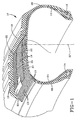
- Figure 1 shows a pneumatic tire in partial sectional view.
- Bead means that part of the tire comprising an annular tensile member wrapped by ply cords and shaped, with our without other reinforcement elements such as flippers, chippers, apexes, toe guards and chafers, to fit the design of the tire rim.
- Belt structure means at least two rubber reinforced annular layers of plies of parallel monofilaments, underlying the tread, unanchored to the bead, and having both left and right cord angles in the range from about 10 to about 30 degrees with respect to the equatorial plane (EP) of the tire.
- EP equatorial plane
- Carcass means the tire structure apart from the belt structure, the tread and the undertread, but including the beads.
- the carcass ply includes reinforcing cords embedded in an elastomeric substance and that these components are considered to be a single entity.
- the "main portion of the carcass ply” means the portion of the carcass ply which extends between the bead cores.
- Core means one or more of the reinforcement elements, formed by one or more filaments/wires which may or may not be twisted or otherwise formed and which may further include strands that may or may not be also so formed.
- “Crown” means that portion of the tire within the width limits of the tire tread.
- Equatorial plane means the plane perpendicular to the tire's axis of rotation and passing through the center of the tire's tread.
- Fatigue Resistance is determined by a three-roll fatigue tester and method described in A Prakash et al, Fatigue Behavior of Wire and Cable, American Society for Metals, pages 405-408 (1985). The procedure is modified to accommodate a monofilament by placing the monofilament in a Tygon® plastic tube instead of being encapsulated in rubber. The diameter of the roller is one inch (2.54 cm) with a tension of 10 percent of the breaking strength of the monofilament.
- Load Range means load and inflation limits for a given tire used in a specific type of service as defined by tables in The Tire and Rim Association, Inc. 1995 Year Book.
- Ply means a continuous layer of rubber-coated parallel filaments.
- Plastic tire means a laminated mechanical device of generally toroidal shape (usually an open-torous) having beads, a carcass ply and a tread.
- Standard Gravel Wheel Test means a laboratory test in which the endurance of a belt package of a tire is evaluated.
- the tire is inflated to 26 psi and tested at 100°F (38°C).
- the tire is tested against a 67.23 inch (1.72 m) diameter flywheel having a row of rounded metal knobs at six locations (every 60°) around the outer circumference. Each row of knobs are across the total width of the flywheel and are approximately 2 inches wide and 1 1/4 inches in height.
- the tire is tested at 35 mph at a load of 1,031 pounds.
- Thread means a molded rubber component which, when bonded to a tire casing, includes that portion of the tire that comes into contact with the road when the tire is normally inflated and under normal load.
- Prefix Letters means those identifications used and defined in The Tire and Rim Association, Inc, 1995 Year Book.
- Ring and radially are used to mean directions radially perpendicular from the axis of rotation through the tire.
- Ring-ply tire means a belted or circumferentially restricted pneumatic tire in which the carcass ply reinforcements which extend from bead to bead are laid at angles between 75° and 105° with respect to the equatorial plane of the tire.
- Ring means the open space between cords in a layer.
- “Section width” means the maximum linear distance parallel to the axis of the tire and between the exterior of its sidewalls when and after it has been inflated at normal pressure for 24 hours, but unloaded, excluding elevations of the sidewalls due to labeling, decoration or protective bands.
- Tensile strength is determined by ASTM E8M-93 as applied to steel wire product.
- pneumatic radial tire comprising:
- the present invention relates to a pneumatic tire 10.
- the pneumatic tire 10 has a carcass ply 12 incorporating a plurality of rubber-coated parallel cords 13. Whereas only one carcass ply 12 is shown, more than one carcass ply may be used, for example, 2, 4, 6 or 8 plies may be used.
- the cords 13 for use in the carcass ply 12 may comprise from one (monofilament) to multiple filaments.
- the number of total filaments in the cord may range from 1 to 13.
- the individual diameter of each filament generally ranges from .15 to .30 mm for each filament.
- the diameter of each filament ranges from .17 mm to .22 mm.
- cord constructions include 1 ⁇ , 2 ⁇ , 3 ⁇ , 4 ⁇ , 5 ⁇ , 6 ⁇ , 7 ⁇ , 8 ⁇ , 11 ⁇ , 12 ⁇ , 1 + 2, 1 + 4, 1 + 5, 1 + 6, 1 + 7, 1 + 8, 2 + 1, 3 + 1, 5 + 1, 6 + 1, 11 + 1, 12 + 1, 2 + 7, 2 + 7 + 1, 3 + 9, 1 + 5 + 1 and 1 + 6 + 1 or 3 + 9 + 1.
- the most preferred cord constructions including filament diameters are 3 ⁇ .18, 1 + 5 ⁇ .18, 1 + 6 ⁇ .18, 2 + 7 ⁇ .18, 2 + 7 ⁇ .18 ⁇ 1 ⁇ .15, 3 + 9 ⁇ .18 + 1 ⁇ .15, 3 + 9 ⁇ .18, 3 ⁇ .20 + 9 ⁇ .18 and 3 ⁇ .20 + 9 ⁇ .18 + 1 ⁇ .15.
- the above cord designations are understandable to those skilled in the art. For example, designations such as 2 ⁇ , 3 ⁇ and 4 ⁇ mean a bunch of filaments; ie, two filaments, three filaments, four filaments and the like. Designations such as 1 + 2 and 1 + 4 indicate, for example, a single filament wrapped by two or four filaments.
- the above cord constructions may be composed of organic fiber or steel.
- the cord construction for the carcass is steel.
- the carcass ply 12 has a layer of the above-described cords 13 arranged so as to have from about 5 to about 70 ends per inch ( ⁇ 2 to 28 ends per cm) when measured at the equatorial plane of the tire.
- the layer of cords are arranged so as to have about 7 to about 20 ends per inch ( ⁇ 2.7 to 8 ends per cm) at the equatorial plane.
- the above calculations for ends per inch are based upon the range of diameters for the cord, strength of the cord and the practical strength requirement for the carcass ply. For example, the high number of ends per inch would include the use of a lower diameter cord for a given strength versus a lower number of ends per inch for a higher diameter wire for the same strength. In the alternative, if one elects to use a cord of a given diameter, one may have to use more or less ends per inch depending on the strength of the cord.
- the steel cord 13 of the carcass ply 12 intersect the equatorial plane (EP) of the tire at an angle in the range of from 75° to 105°.
- the steel cords intersect at an angle of from 82° to 98°.
- the preferred range is from 89° to 91°.
- a tire 10 according to the present invention has a pair of axially spaced-apart bead cores 14,16 which each comprise a plurality of wraps of a single metallic filament.
- the carcass ply 12 extends between the beads 14,16 and is folded thereabout.
- Each of the bead cores 14,16 has a radial cross-sectional shape which may be substantially pentagonal, hexagonal, rectangular or circular. In the instance where the bead has a radial cross-sectional shape which is substantially pentagonal, the greatest axial width of the bead core is located radially outwardly of the radially innermost edge of the bead core.
- a "radial cross section” is a cross section taken in a plane which contains the axis of rotation of a tire or tire and rim assembly.
- substantially pentagonal is understood to mean a five-sided cross section, even though some or all of the sides may be curvilinear rather than rectilinear, as in a regular pentagon.
- the radially outermost extent of the bead core being a vertex of two of the sides of the pentagon and the greatest axial width of the bead core being located radially outwardly of the radially innermost edge of the bead core.
- the pneumatic tire 10 has a conventional tread 18 disposed on the crown of the carcass 12.
- the pneumatic tire 10 has a belt structure comprising at least two belt ply layers 20, 22.
- One critical aspect of the invention is a belt structure comprising at least two belt ply layers 20,22 reinforced with parallel metallic monofilament cords 19.
- One way of achieving such strength is by merging the proper process and alloys as disclosed in U.S. Patent 4,960,473 and 5,066,455, with a steel rod microalloyed with one or more of the following elements: Ni, Cr, Nb, Si, Mo, Mn, Cu, Co, V and B.
- the preferred chemistry is listed below in weight percentages: C 0.82 to 1.0 Mn 0.30 to 0.50 Si 0.10 to 0.30 Cr 0 to 0.4 V 0 to 0.1 Cu 0 to 0.5 Ni 0 to 0.5 Co 0 to 0.1 the balance being iron and residuals The resulting rod is then drawn to the appropriate tensile strength.
- the monofilament cords used in the belt structure of the present invention have higher strength and higher fatigue life over prior art monofilament cords used in belt structures. These advantages lead to pneumatic tires which have less reinforcement material and thus lower weight and cost. Further the life of the tire can be increased with the increase in fatigue resistance of the monofilament.
- the belt structures incorporate monofilament cords, there is a resulting reduction in gauge material and cost as compared with the use of cords containing more than one filament, making the tires lighter in weight and less costly.
- the individual diameter (D) of each monofilament cord generally ranges from .25 mm to .40 mm having at least a tensile strength of 4080 MPa -(2000 ⁇ D) ⁇ 95 percent where D is the filament diameter in mm.
- the tensile strength of each monofilament cord is at least 4400 MPa -(2000 ⁇ D) ⁇ 95 percent.
- the diameter of each monofilament cord ranges from .30 to .35 mm.
- the total elongation should be at least 2 percent over a gauge length of 25 centimeters. Total elongation is measured according to ASTM A370-92. Preferably, the total elongation of the monofilament cord ranges from about 2 percent to 4 percent. A particularly preferred total elongation ranges from about 2.2 to about 3.0.
- the torsion values for the monofilament cord should be at least 20 turns with a gauge length of 200 times the diameter of the wire. Generally, the torsion value ranges from about 20 to about 100 turns. Preferably, the torsion values range from about 30 to about 80 turns with a range of at least 50 turns being particularly preferred.
- the torsion values are determined according to ASTM Test Method E 558-83 with test lengths of 200 times the diameter of the wire.
- the monofilaments for use in the belt ply layers 20,22 must have a fatigue resistance of at least 3500 cycles as measured by the 3 Roll Bending Fatigue Test.
- the monofilament has a fatigue resistance ranging from 3500 to 6000, with a range of at least 4000 cycles being particularly preferred.
- Each belt ply layer 20,22 has a layer of steel monofilaments arranged so as to have from about 25 to 60 ends per inch (25.4 cm).
- the layer of steel monofilament cords are arranged so as to have about 30 to 50 ends per inch (25.4 cm).
- a gum rubber in a flat or wedge shape, 23, is disposed between axially outer belt edges 25,27 of the two belt ply layers 20,22.
- a substantially air impervious layer 24 is disposed inwardly of the carcass ply 12 and contiguous to an inflation chamber defined by the volume bounded by the tire 10 and rim assembly (not shown).
- a barrier layer (not shown) is disposed between the air impervious layer 24 and the carcass ply 12. The barrier ply functions to separate the air impervious layer from the elastomeric layer in which the steel monofilaments of the carcass ply 12 are embedded.
- Elastomeric sidewalls 26, 28 are disposed axially outwardly of the carcass structure.
- steel monofilament cords in the belt ply layers as disclosed herein may be applied to general passenger radial tires as well as racing tires, agricultural tires, motor cycles, small or medium size truck tires and leisure vehicle tires.
- the pneumatic tires of the present invention are directed to passenger tires and medium to light truck tires.
- the pneumatic tires of the present invention may be designed for various load ranges.
- the load ranges may be A, B, C, D or E.
- the load range is E.
- the pneumatic tires of the present invention may also be designated by various prefix letters depending on the designed service conditions requiring different loads and inflations.
- the tires may be designated by AT, LT, P and ST.
- the pneumatic tire is LT.
Landscapes
- Engineering & Computer Science (AREA)
- Mechanical Engineering (AREA)
- Tires In General (AREA)
Claims (10)
- Bandage pneumatique radial (10) comprenantlesdits câblés (19) constitués par des monofilaments étant posés en une quantité telle que l'on obtient un nombre de bouts se situant dans le domaine de 25 à 60 bouts par pouce (25,4 mm), chaque câblé (19) constitué par des monofilaments possédant un diamètre de 0,25 à 0,40 mm, une résistance à la traction d'au moins 4080 MPa - (2000 x D) x 95 pour cent, où D représente le diamètre des filaments en millimètres, et une résistance à la fatigue d'au moins 3500 cycles telle qu'on la mesure via l'essai de résistance à la fatigue par flexion dans lequel on utilise trois cylindres, décrit dans A. Prakash et collaborateurs, Fatigue Behaviour of Wire and Cable, American Society for Metals, 1985.(a) une nappe de carcasse radiale (12) possédant une région de couronne;(b) une bande de roulement (18) disposée en direction radiale à l'extérieur de ladite région de couronne; et(c) au moins deux couches de nappes de ceintures (20, 22) disposées entre la bande de roulement (18) et la région de couronne de la nappe de carcasse (12), dans lequel chaque couche de nappe de ceinture (20, 22) est composée d'une couche renforcée du caoutchouc dans laquelle sont enrobés plusieurs câblés parallèles (19) espacés les uns des autres et constitués par des monofilaments en acier, qui sont inclinés en formant un angle entre 10° et 30° par rapport au plan équatorial (EP),(d) un pont de gomme (23) de forme plate ou cunéiforme disposé entre les bords de ceintures externes en direction axiale des deux couches de nappes de ceintures (20, 22),
- Bandage pneumatique selon la revendication 1, caractérisé en ce que ladite résistance à la traction s'élève à au moins 4400 MPa - (2000 x D) x 95 pour cent.
- Bandage pneumatique selon la revendication 1, caractérisé en ce que ledit diamètre D dudit câblé (19) constitué par des monofilaments se situe dans le domaine de 0,30 à 0,35 mm.
- Bandage pneumatique selon la revendication 1, caractérisé en ce que ledit câblé (19) constitué par des monofilaments possède une résistance à la fatigue de 3500 à 6000 cycles.
- Bandage pneumatique selon la revendication 1, caractérisé en ce que ledit câblé (19) constitué par des monofilaments possède une résistance à la fatigue d'au moins 4000 cycles.
- Bandage pneumatique selon la revendication 1, caractérisé en ce que ledit câblé (19) constitué par des monofilaments possède un allongement total de 2 pour cent à 3 pour cent.
- Bandage pneumatique selon la revendication 1, caractérisé en ce que ledit câblé (19) constitué par des monofilaments possède une valeur de torsion d'au moins 20 spires avec une longueur nominale représentant 200 fois le diamètre dudit monofilament.
- Bandage pneumatique selon la revendication 1, caractérisé en ce que lesdits câblés (19) sont constitués par des monofilaments en une quantité telle que l'on obtient un nombre de bouts se situant dans le domaine de 30 à 50 bouts par pouce (25,4 mm).
- Bandage pneumatique selon la revendication 1, caractérisé en ce que ledit bandage pneumatique est un bandage pneumatique (10) pour véhicule de tourisme.
- Bandage pneumatique selon la revendication 1, caractérisé en ce que ledit bandage pneumatique possède un domaine de charge choisi parmi le groupe constitué par A, B, C, D et E, tels que définis par des tableaux dans le Tire and Rim Association, Inc. 1995 Year Book.
Applications Claiming Priority (2)
| Application Number | Priority Date | Filing Date | Title |
|---|---|---|---|
| US611391 | 1996-03-06 | ||
| US08/611,391 US5858137A (en) | 1996-03-06 | 1996-03-06 | Radial tires having at least two belt plies reinforced with steel monofilaments |
Publications (2)
| Publication Number | Publication Date |
|---|---|
| EP0795426A1 EP0795426A1 (fr) | 1997-09-17 |
| EP0795426B1 true EP0795426B1 (fr) | 2001-11-21 |
Family
ID=24448836
Family Applications (1)
| Application Number | Title | Priority Date | Filing Date |
|---|---|---|---|
| EP97103104A Expired - Lifetime EP0795426B1 (fr) | 1996-03-06 | 1997-02-26 | Bandages pneumatiques radiaux ayant au moins deux plis de sommet armés de monofilaments d'acier |
Country Status (5)
| Country | Link |
|---|---|
| US (1) | US5858137A (fr) |
| EP (1) | EP0795426B1 (fr) |
| JP (1) | JP4005658B2 (fr) |
| CA (1) | CA2176861A1 (fr) |
| DE (1) | DE69708355T2 (fr) |
Cited By (1)
| Publication number | Priority date | Publication date | Assignee | Title |
|---|---|---|---|---|
| WO2012048930A1 (fr) | 2010-10-14 | 2012-04-19 | Continental Reifen Deutschland Gmbh | Pneumatique de véhicule |
Families Citing this family (38)
| Publication number | Priority date | Publication date | Assignee | Title |
|---|---|---|---|---|
| US6247514B1 (en) * | 1994-12-20 | 2001-06-19 | The Goodyear Tire & Rubber Company | Tires with high strength reinforcement |
| FI103463B1 (fi) * | 1997-04-23 | 1999-06-30 | Nokia Mobile Phones Ltd | Tietokone ja menetelmä tietokoneen käyttämiseksi |
| US6223797B1 (en) | 1998-01-29 | 2001-05-01 | The Yokohama Rubber Co. | Pneumatic tire with specified rubber properties |
| DE69921236T2 (de) * | 1998-06-23 | 2006-03-09 | Sumitomo Rubber Industries Ltd., Kobe | Radialer Lkw-Reifen |
| DE60018547T2 (de) * | 1999-12-22 | 2006-04-13 | Sumitomo Rubber Industries Ltd., Kobe | Luftreifen |
| JP2001334809A (ja) * | 2000-05-24 | 2001-12-04 | Bridgestone Corp | 空気入りラジアルタイヤ |
| US20050269005A1 (en) * | 2000-09-20 | 2005-12-08 | Steinke Richard A | Air no air elastomeric tire |
| ES2257530T3 (es) * | 2001-03-16 | 2006-08-01 | Bridgestone Corporation | Cubiertas neumaticas. |
| FR2836655B1 (fr) * | 2002-03-04 | 2005-02-11 | Michelin Soc Tech | Armature de sommet avec nappe d'epaule |
| JP4535430B2 (ja) * | 2004-06-11 | 2010-09-01 | 株式会社ブリヂストン | 空気入りラジアルタイヤ |
| JP4596526B2 (ja) * | 2004-12-21 | 2010-12-08 | 株式会社ブリヂストン | 空気入りラジアルタイヤ |
| FR2887815A1 (fr) * | 2005-06-30 | 2007-01-05 | Michelin Soc Tech | Pneumatique pour vehicules lourds |
| FR2887812A1 (fr) * | 2005-06-30 | 2007-01-05 | Michelin Soc Tech | Pneumatique pour vehicules lourds |
| US20070131332A1 (en) * | 2005-12-14 | 2007-06-14 | Cornelius Maus Peter J | Pneumatic tire with monofilament reinforcement |
| US20130206302A1 (en) * | 2010-06-29 | 2013-08-15 | The Yokohama Rubber Co., Ltd. | Pneumatic tire |
| US9073389B2 (en) | 2011-10-21 | 2015-07-07 | Bridgestone Americas Tire Operations, Llc | All steel fabric radial construction for agricultural tires |
| CN104010832A (zh) * | 2011-12-26 | 2014-08-27 | 横滨橡胶株式会社 | 充气子午轮胎 |
| FR2986740B1 (fr) * | 2012-02-09 | 2014-03-21 | Michelin & Cie | Pneumatique a structure de ceinture allegee |
| FR2986739B1 (fr) | 2012-02-09 | 2014-03-21 | Michelin & Cie | Pneumatique a structure de ceinture allegee |
| US20140174614A1 (en) * | 2012-12-21 | 2014-06-26 | Bridgestone Americas Tire Operations, Llc | Agricultural Radial Implement Tire |
| CN109822008B (zh) | 2013-07-29 | 2021-06-18 | 贝卡尔特公司 | 用于带束层上的直的单丝 |
| FR3009238B1 (fr) * | 2013-07-30 | 2016-10-28 | Michelin & Cie | Pneu radial a structure de ceinture allegee |
| CN105408127B (zh) | 2013-07-30 | 2017-03-15 | 米其林集团总公司 | 具有轻质带束层结构的子午线轮胎 |
| JP2017500250A (ja) | 2013-12-24 | 2017-01-05 | ブリヂストン アメリカズ タイヤ オペレーションズ、 エルエルシー | ラップアラウンドガムストリップを有するベルトを備えるタイヤ |
| JP6423674B2 (ja) * | 2014-10-01 | 2018-11-14 | 株式会社ブリヂストン | 空気入りタイヤ |
| FR3032147B1 (fr) | 2015-02-03 | 2017-02-17 | Michelin & Cie | Pneu radial ayant une structure de ceinture amelioree |
| FR3032150A1 (fr) | 2015-02-03 | 2016-08-05 | Michelin & Cie | Pneu radial ayant une structure de ceinture amelioree |
| FR3032149B1 (fr) | 2015-02-03 | 2017-02-17 | Michelin & Cie | Pneu radial ayant une structure de ceinture tres fine |
| FR3032151B1 (fr) | 2015-02-03 | 2017-02-17 | Michelin & Cie | Pneu radial ayant une structure de ceinture amelioree |
| FR3048638B1 (fr) | 2016-03-11 | 2018-03-30 | Compagnie Generale Des Etablissements Michelin | Pneu radial ayant une structure de ceinture amelioree |
| FR3051143A1 (fr) * | 2016-05-11 | 2017-11-17 | Michelin & Cie | Pneumatique a couches de travail comprenant des monofilaments pour eviter la fissuration |
| DE102016225231A1 (de) | 2016-11-25 | 2018-05-30 | Continental Reifen Deutschland Gmbh | Fahrzeugluftreifen mit einer Gürtellage aufweisend Stahl-Monofilamente |
| WO2022145112A1 (fr) * | 2020-12-28 | 2022-07-07 | 住友ゴム工業株式会社 | Pneumatique |
| EP4269494B1 (fr) * | 2020-12-28 | 2025-06-18 | Sumitomo Rubber Industries, Ltd. | Pneumatique |
| CN116635246A (zh) * | 2020-12-28 | 2023-08-22 | 住友橡胶工业株式会社 | 充气轮胎 |
| JP7900650B2 (ja) * | 2021-05-06 | 2026-08-05 | 横浜ゴム株式会社 | タイヤ |
| JP7877677B2 (ja) * | 2021-12-23 | 2026-06-23 | 住友ゴム工業株式会社 | タイヤ |
| DE102022205545A1 (de) * | 2022-05-31 | 2023-11-30 | Continental Reifen Deutschland Gmbh | Fahrzeugluftreifen aufweisend eine Festigkeitsträgerlage mit Stahl-Monofilamenten |
Family Cites Families (18)
| Publication number | Priority date | Publication date | Assignee | Title |
|---|---|---|---|---|
| BE560044A (fr) * | 1954-02-26 | |||
| DE1182973B (de) * | 1958-09-05 | 1964-12-03 | Continental Gummi Werke Ag | Fahrzeugluftreifen |
| US3802982A (en) * | 1970-01-06 | 1974-04-09 | Steelastic Co | Reinforced tire fabric and method and apparatus for making same |
| FR2421742A1 (fr) * | 1978-04-07 | 1979-11-02 | Michelin & Cie | Pneumatique a carcasse radiale |
| IT1132524B (it) * | 1980-07-08 | 1986-07-02 | Pneumatici Pirelli Sa Soc | Perfezionamenti alla struttura anulare di rinforzo dei pneumatici raidali |
| BE892858A (fr) * | 1981-04-16 | 1982-08-02 | Pirelli | Pneumatique pour vehicules automobiles a basse absorption de puissance |
| US4546031A (en) * | 1983-08-15 | 1985-10-08 | The Goodyear Tire & Rubber Company | Reinforcing element for elastomeric articles and elastomeric made thereof |
| JPS62170594A (ja) * | 1986-01-17 | 1987-07-27 | 東京製綱株式会社 | ゴム補強用スチ−ルコ−ド |
| EP0414892B1 (fr) * | 1989-03-08 | 1993-09-01 | Bridgestone Corporation | Pneu radial |
| USH1333H (en) * | 1990-03-21 | 1994-07-05 | Helfer Farrel B | High strength reinforcement |
| JPH04281081A (ja) * | 1991-03-06 | 1992-10-06 | Bridgestone Corp | ゴム補強用金属コ−ド及びこれを使用したタイヤ |
| FR2684605B1 (fr) * | 1991-12-04 | 1994-01-28 | Michelin Et Cie | Pneumatique radial dont l'armature de sommet est composee de nappes de resistances differentes. |
| JPH05238202A (ja) * | 1992-02-27 | 1993-09-17 | Yokohama Rubber Co Ltd:The | 乗用車用空気入りラジアルタイヤ |
| JP3180166B2 (ja) * | 1992-06-05 | 2001-06-25 | 横浜ゴム株式会社 | 空気入りラジアルタイヤ |
| CA2100538A1 (fr) * | 1992-10-21 | 1994-04-22 | Johnny Dale Ii Massie | Pneu resistant aux coupures |
| US5386860A (en) * | 1992-10-21 | 1995-02-07 | The Goodyear Tire & Rubber Company | Cut resistant tire |
| DE4334650C1 (de) * | 1993-10-12 | 1995-03-02 | Uniroyal Englebert Gmbh | Fahrzeugluftreifen mit Radialkarkasse |
| AT401369B (de) * | 1994-04-28 | 1996-08-26 | Semperit Ag | Fahrzeugreifen in radialbauart |
-
1996
- 1996-03-06 US US08/611,391 patent/US5858137A/en not_active Expired - Lifetime
- 1996-05-17 CA CA002176861A patent/CA2176861A1/fr not_active Abandoned
-
1997
- 1997-02-26 DE DE69708355T patent/DE69708355T2/de not_active Expired - Fee Related
- 1997-02-26 EP EP97103104A patent/EP0795426B1/fr not_active Expired - Lifetime
- 1997-02-27 JP JP04355997A patent/JP4005658B2/ja not_active Expired - Fee Related
Cited By (2)
| Publication number | Priority date | Publication date | Assignee | Title |
|---|---|---|---|---|
| WO2012048930A1 (fr) | 2010-10-14 | 2012-04-19 | Continental Reifen Deutschland Gmbh | Pneumatique de véhicule |
| DE102010038199A1 (de) | 2010-10-14 | 2012-04-19 | Continental Reifen Deutschland Gmbh | Fahrzeugluftreifen |
Also Published As
| Publication number | Publication date |
|---|---|
| DE69708355D1 (de) | 2002-01-03 |
| DE69708355T2 (de) | 2002-08-08 |
| CA2176861A1 (fr) | 1997-09-07 |
| JPH09323503A (ja) | 1997-12-16 |
| JP4005658B2 (ja) | 2007-11-07 |
| US5858137A (en) | 1999-01-12 |
| EP0795426A1 (fr) | 1997-09-17 |
Similar Documents
| Publication | Publication Date | Title |
|---|---|---|
| US5858137A (en) | Radial tires having at least two belt plies reinforced with steel monofilaments | |
| US6719030B2 (en) | Pneumatic tire having a single carcass ply reinforced with metallic cords, a high ending ply, turnup and locked bead construction | |
| EP1209009B1 (fr) | Bandage pneumatique | |
| EP0849098A1 (fr) | Pneumatiques avec renforcement de haute resistance | |
| EP2186652B1 (fr) | Pneu pour motocyclette pour déplacement en terrain accidenté | |
| US20110253279A1 (en) | Tyre reinforced with steel cords comprising fine filaments | |
| US5242001A (en) | Pneumatic radial tire including steel belt cords of 2+2 ST construction | |
| US6959745B2 (en) | Steel cord, method of making the same and pneumatic tire including the same | |
| EP3339058B1 (fr) | Pneumatique | |
| EP1262337A2 (fr) | Bandage pneumatique | |
| US20010013385A1 (en) | Pneumatic tire | |
| JP2918349B2 (ja) | 航空機用空気入りバイアスプライタイヤ | |
| KR20010013070A (ko) | 튜브리스 타이어 및 그 제조 방법 | |
| US20120067491A1 (en) | Tires with high strength reinforcement | |
| EP0937588A2 (fr) | Pneu radial comportant des torons à fils d'acier non-tordus dans une couche de ceinture | |
| EP0644070A1 (fr) | Bandages pneumatiques contenant des monofilaments d'acier dans la nappe de carcasse | |
| KR20220018927A (ko) | 타이어용 전단 밴드 구조체 | |
| EP0937587A2 (fr) | Pneu radial comportant des torons à fils d'acier non-tordus dans la couche de carcasse | |
| US20120067490A1 (en) | Tires with high strength reinforcement | |
| US20230098208A1 (en) | Wraparound structure for a belt package of a tire | |
| US20120067488A1 (en) | Tires with high strength reinforcement | |
| MXPA99001546A (en) | Radial wheels containing non-retridated steel filament hebras in a layer of ba sheet | |
| US20120067489A1 (en) | Tires with high strength reinforcement | |
| MXPA98001237A (en) | Pneumatic rim that has a single reinforced cover coat with metallic strings, a construction of extreme heavy coat, folded up and before enclav |
Legal Events
| Date | Code | Title | Description |
|---|---|---|---|
| PUAI | Public reference made under article 153(3) epc to a published international application that has entered the european phase |
Free format text: ORIGINAL CODE: 0009012 |
|
| 17P | Request for examination filed |
Effective date: 19970226 |
|
| AK | Designated contracting states |
Kind code of ref document: A1 Designated state(s): DE FR GB IT |
|
| GRAG | Despatch of communication of intention to grant |
Free format text: ORIGINAL CODE: EPIDOS AGRA |
|
| 17Q | First examination report despatched |
Effective date: 20010122 |
|
| GRAG | Despatch of communication of intention to grant |
Free format text: ORIGINAL CODE: EPIDOS AGRA |
|
| GRAH | Despatch of communication of intention to grant a patent |
Free format text: ORIGINAL CODE: EPIDOS IGRA |
|
| GRAH | Despatch of communication of intention to grant a patent |
Free format text: ORIGINAL CODE: EPIDOS IGRA |
|
| GRAA | (expected) grant |
Free format text: ORIGINAL CODE: 0009210 |
|
| AK | Designated contracting states |
Kind code of ref document: B1 Designated state(s): DE FR GB IT |
|
| REG | Reference to a national code |
Ref country code: GB Ref legal event code: IF02 |
|
| REF | Corresponds to: |
Ref document number: 69708355 Country of ref document: DE Date of ref document: 20020103 |
|
| ET | Fr: translation filed | ||
| PLBE | No opposition filed within time limit |
Free format text: ORIGINAL CODE: 0009261 |
|
| STAA | Information on the status of an ep patent application or granted ep patent |
Free format text: STATUS: NO OPPOSITION FILED WITHIN TIME LIMIT |
|
| 26N | No opposition filed | ||
| PGFP | Annual fee paid to national office [announced via postgrant information from national office to epo] |
Ref country code: GB Payment date: 20050110 Year of fee payment: 9 |
|
| PGFP | Annual fee paid to national office [announced via postgrant information from national office to epo] |
Ref country code: FR Payment date: 20060202 Year of fee payment: 10 |
|
| PG25 | Lapsed in a contracting state [announced via postgrant information from national office to epo] |
Ref country code: GB Free format text: LAPSE BECAUSE OF NON-PAYMENT OF DUE FEES Effective date: 20060226 |
|
| PGFP | Annual fee paid to national office [announced via postgrant information from national office to epo] |
Ref country code: DE Payment date: 20060228 Year of fee payment: 10 |
|
| GBPC | Gb: european patent ceased through non-payment of renewal fee |
Effective date: 20060226 |
|
| REG | Reference to a national code |
Ref country code: FR Ref legal event code: ST Effective date: 20071030 |
|
| PG25 | Lapsed in a contracting state [announced via postgrant information from national office to epo] |
Ref country code: DE Free format text: LAPSE BECAUSE OF NON-PAYMENT OF DUE FEES Effective date: 20070901 |
|
| PG25 | Lapsed in a contracting state [announced via postgrant information from national office to epo] |
Ref country code: FR Free format text: LAPSE BECAUSE OF NON-PAYMENT OF DUE FEES Effective date: 20070228 |
|
| PGFP | Annual fee paid to national office [announced via postgrant information from national office to epo] |
Ref country code: IT Payment date: 20080221 Year of fee payment: 12 |
|
| PG25 | Lapsed in a contracting state [announced via postgrant information from national office to epo] |
Ref country code: IT Free format text: LAPSE BECAUSE OF NON-PAYMENT OF DUE FEES Effective date: 20090226 |