EP0795496A1 - Kettenförderer mit selbsthaltenden Gelenkbolzen - Google Patents
Kettenförderer mit selbsthaltenden Gelenkbolzen Download PDFInfo
- Publication number
- EP0795496A1 EP0795496A1 EP96308458A EP96308458A EP0795496A1 EP 0795496 A1 EP0795496 A1 EP 0795496A1 EP 96308458 A EP96308458 A EP 96308458A EP 96308458 A EP96308458 A EP 96308458A EP 0795496 A1 EP0795496 A1 EP 0795496A1
- Authority
- EP
- European Patent Office
- Prior art keywords
- eye
- opening
- hinge pin
- eyes
- conveyor
- Prior art date
- Legal status (The legal status is an assumption and is not a legal conclusion. Google has not performed a legal analysis and makes no representation as to the accuracy of the status listed.)
- Granted
Links
Images

Classifications
-
- B—PERFORMING OPERATIONS; TRANSPORTING
- B65—CONVEYING; PACKING; STORING; HANDLING THIN OR FILAMENTARY MATERIAL
- B65G—TRANSPORT OR STORAGE DEVICES, e.g. CONVEYORS FOR LOADING OR TIPPING, SHOP CONVEYOR SYSTEMS OR PNEUMATIC TUBE CONVEYORS
- B65G17/00—Conveyors having an endless traction element, e.g. a chain, transmitting movement to a continuous or substantially-continuous load-carrying surface or to a series of individual load-carriers; Endless-chain conveyors in which the chains form the load-carrying surface
-
- F—MECHANICAL ENGINEERING; LIGHTING; HEATING; WEAPONS; BLASTING
- F16—ENGINEERING ELEMENTS AND UNITS; GENERAL MEASURES FOR PRODUCING AND MAINTAINING EFFECTIVE FUNCTIONING OF MACHINES OR INSTALLATIONS; THERMAL INSULATION IN GENERAL
- F16G—BELTS, CABLES, OR ROPES, PREDOMINANTLY USED FOR DRIVING PURPOSES; CHAINS; FITTINGS PREDOMINANTLY USED THEREFOR
- F16G13/00—Chains
- F16G13/02—Driving-chains
- F16G13/06—Driving-chains with links connected by parallel driving-pins with or without rollers so-called open links
- F16G13/07—Driving-chains with links connected by parallel driving-pins with or without rollers so-called open links the links being of identical shape, e.g. cranked
-
- B—PERFORMING OPERATIONS; TRANSPORTING
- B65—CONVEYING; PACKING; STORING; HANDLING THIN OR FILAMENTARY MATERIAL
- B65G—TRANSPORT OR STORAGE DEVICES, e.g. CONVEYORS FOR LOADING OR TIPPING, SHOP CONVEYOR SYSTEMS OR PNEUMATIC TUBE CONVEYORS
- B65G17/00—Conveyors having an endless traction element, e.g. a chain, transmitting movement to a continuous or substantially-continuous load-carrying surface or to a series of individual load-carriers; Endless-chain conveyors in which the chains form the load-carrying surface
- B65G17/06—Conveyors having an endless traction element, e.g. a chain, transmitting movement to a continuous or substantially-continuous load-carrying surface or to a series of individual load-carriers; Endless-chain conveyors in which the chains form the load-carrying surface having a load-carrying surface formed by a series of interconnected, e.g. longitudinal, links, plates, or platforms
- B65G17/08—Conveyors having an endless traction element, e.g. a chain, transmitting movement to a continuous or substantially-continuous load-carrying surface or to a series of individual load-carriers; Endless-chain conveyors in which the chains form the load-carrying surface having a load-carrying surface formed by a series of interconnected, e.g. longitudinal, links, plates, or platforms the surface being formed by the traction element
-
- F—MECHANICAL ENGINEERING; LIGHTING; HEATING; WEAPONS; BLASTING
- F16—ENGINEERING ELEMENTS AND UNITS; GENERAL MEASURES FOR PRODUCING AND MAINTAINING EFFECTIVE FUNCTIONING OF MACHINES OR INSTALLATIONS; THERMAL INSULATION IN GENERAL
- F16G—BELTS, CABLES, OR ROPES, PREDOMINANTLY USED FOR DRIVING PURPOSES; CHAINS; FITTINGS PREDOMINANTLY USED THEREFOR
- F16G13/00—Chains
- F16G13/02—Driving-chains
- F16G13/08—Driving-chains with links closely interposed on the joint pins
-
- B—PERFORMING OPERATIONS; TRANSPORTING
- B65—CONVEYING; PACKING; STORING; HANDLING THIN OR FILAMENTARY MATERIAL
- B65G—TRANSPORT OR STORAGE DEVICES, e.g. CONVEYORS FOR LOADING OR TIPPING, SHOP CONVEYOR SYSTEMS OR PNEUMATIC TUBE CONVEYORS
- B65G2201/00—Indexing codes relating to handling devices, e.g. conveyors, characterised by the type of product or load being conveyed or handled
- B65G2201/02—Articles
-
- B—PERFORMING OPERATIONS; TRANSPORTING
- B65—CONVEYING; PACKING; STORING; HANDLING THIN OR FILAMENTARY MATERIAL
- B65G—TRANSPORT OR STORAGE DEVICES, e.g. CONVEYORS FOR LOADING OR TIPPING, SHOP CONVEYOR SYSTEMS OR PNEUMATIC TUBE CONVEYORS
- B65G2207/00—Indexing codes relating to constructional details, configuration and additional features of a handling device, e.g. Conveyors
- B65G2207/12—Chain pin retainers
Definitions
- the invention relates generally to belt, chain, or conveyor construction, and, in particular, to systems or arrangements for preventing unwanted axial migration of a hinge pin connecting two adjacent belt, chain, or conveyor elements.
- the axial loads on a hinge pin in a belt, chain, or conveyor are such that a hinge pin retention system is needed to prevent the hinge pin from axially migrating and forcing its way out of engagement with the axially adjacent elements of the belt, chain, or conveyor.
- plugs have been employed for retaining hinge pins against axial movement in thermoplastic chains and belts. These plugs have been retained in the links of the chain or belt by cantilever style snap fits with barbed ends. In these products, the hinge pin places a tensile load on the barbed cantilevered arms.
- the invention provides a conveyor comprising a first conveyor element including an end comprising an interiorly located eye including therein an opening, and an end eye adjacently spaced from said interior eye to define therebetween a space and including therein an opening located in axial alignment with said opening in said interiorly located eye and having a given diameter, a second conveyor element including an end comprising an eye extending into said space between said end eye and said interiorly located eye and including therein an opening axially aligned with respect to said openings in said end eye and said interiorly located eye, and a hinge pin including a cylindrical portion extending in said opening in said interiorly located eye of said first conveyor element and in said opening in said eye of said second conveyor element, and an end portion including a barb which resiliently extends radially outwardly to normally prevent axially outward passage of said hinge pin through said opening in said end eye and which is resiliently deformable to a radially inward location to permit passage of said hinge pin through said opening in said end eye.
- the invention also provides a conveyor comprising a first conveyor element including an end comprising an interiorly located eye including therein an opening, and an end eye adjacently spaced from the interior eye to define therebetween a space and including therein an opening located in axial alignment with the opening in the interiorly located eye and having a given dimension, a second conveyor element including an end comprising an eye extending into the space between the end eye and the interiorly located eye and including therein an opening axially aligned with respect to the openings in the end eye and the interiorly located eye, and a hinge pin including a cylindrical portion extending in the opening in the interiorly located eye of the first conveyor element and in the opening in the eye of the second conveyor element, and an axially outwardly diverging end portion extending axially from the cylindrical portion and including an axially extending slot defining opposed barbs having outer ends located in adjacent relation to the end eye and having a dimension greater than the dimension of the opening in the end eye so as to normally be impassable through the opening in the end eye, whereby to normally prevent
- the invention also provides a conveyor comprising a first conveyor element including an end comprising a first series of eyes spaced from each other, defining therebetween a series of spaces, and including a sub-series of centrally located eyes respectively including therein openings aligned with respect to each other and having a given dimension, and an end eye adjacent one end of the sub-series of centrally located eyes and including therein an opening located in axial alignment with the openings of the sub-series of centrally located eyes and having a diameter generally equal to the diameter of the openings in the sub-series of centrally located eyes, a second conveyor element including an end comprising a series of eyes spaced from each other, extending into the spaces between the eyes of the first conveyor element, defining therebetween a series of spaces receiving the eyes of the first conveyor element, and respectively including therein openings axially aligned with respect to each other and with respect to the openings of the sub-series of the centrally located eyes of the first conveyor element, and having a dimension generally equal to the dimension of the opening
- the invention also provides a conveyor comprising a first conveyor element including an end comprising a first series of eyes spaced from each other, defining therebetween a series of spaces, and including a sub-series of centrally located eyes respectively including therein openings aligned with respect to each other and having a given diameter, and a first end eye located adjacent one end of the sub-series of centrally located eyes and including therein a central slot defining an inner end eye portion having therein an opening located in axial alignment with the openings in the sub-series of centrally located eyes and having a diameter substantially equal to the given diameter, and an outer eye portion located in axial alignment with the openings in the sub-series of centrally located eyes and having a diameter substantially equal to the given diameter, and a second end eye located adjacent the other end of the sub-series of centrally located eyes and including therein a central slot defining an inner end eye portion having therein an opening located in axial alignment with the openings in the sub-series of centrally located eyes and having a diameter substantially equal
- Figure 1 is a perspective view of one embodiment of a conveyor, track, or belt which includes various of the features of the invention.
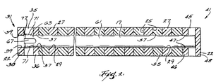
- Figure 2 is a sectional view taken along line 2-2 of Figure 1.
- Figure 3 is a sectional view which is similar to Figure 2 and which illustrates another embodiment of a conveyor, track, or belt including various of the features of the invention.
- Figure 4 is a sectional view which is similar to Figure 2 and which illustrates still another embodiment of a conveyor, track, or belt including various of the features of the invention.
- Figure 5 is a fragmentary, enlarged sectional view of a portion of the constructions shown in Figure 2.
- FIG. 1 Illustrated in Figures 1, 2, and 5 is a first embodiment of a conveyor, belt, or track 11 comprising first and second conveyor elements 13 and 15 and a hinge pin 17.
- the invention is applicable to any type of track assembly or conveyor, and, except as noted hereinafter, the conveyor elements can take any conventional form and can be fabricated of any suitable material.
- the first conveyor element 13 can be fabricated of any suitable substantially rigid material, such as thermoplastic material, and includes laterally spaced and generally rectilinearly extending sides 22, together with an end 21 located between the sides 22 and comprising a series of eyes 23 which are spaced from each other to define therebetween a series of spaces 25.
- the series of eyes 23 includes a sub-series of centrally located eyes 27 respectively including therein openings or bores 29 aligned with respect to each other and having a given diameter.
- the series of eyes 23 also includes (see Figure 2) a first end eye 31 located adjacent one end of the sub-series of centrally located eyes 27 and inwardly of the associated lateral side 22.
- the series of eyes 23 also includes a second end eye 41 located adjacent the other end of the sub-series of centrally located eyes 27.
- the first and second end eyes 31 and 41 respectively include therein central slots 35 and 45 defining inner end eye portions 36 and 46 having therein respective openings or bores 37 and 47 located in axial alignment with the openings 29 in the sub-series of centrally located eyes 27 and having a diameter substantially equal to the given diameter of the openings 29.
- the end eyes 31 and 41 also define respective outer eye portions 38 and 48, the eye portion 38 having therein a respective opening or bore 39 located in axial alignment with the openings 29 in the sub-series of centrally located eyes 27 and having a diameter substantially equal to the given diameter of the openings 29.
- the eye portion 48 is a blind eye and does not include a bore.
- the slots 35 and 45 permit visual determination of the presence or absence of the hinge pin in the end eyes 31 and 41 and slot 35 also allows access for a pair of conventional pliers, such as needle nose pliers, to squeeze the expanded end portions 63, thus allowing removal of the hinge pin 17.
- the slot 67 also permits the end of the hinge pin to expand in the event of an axial load on the hinge pin 17 against the inside surface of the end eye 31.
- the second conveyor element 15 can be fabricated of any suitable substantially rigid material, such as thermoplastic material or steel, and includes laterally spaced and generally rectilinearly extending sides 52, together with an end 51 extending between the sides 52 and comprising a series of eyes 53 which are spaced from each other and extend into the spaces 25 between the eyes 23 of the first conveyor element 13.
- the spacing of the eyes 53 also defines a series of spaces 55 receiving the centrally located eyes 27 of the first conveyor element 13.
- the series of eyes 53 also respectively includes therein openings or bores 57 axially aligned with respect to each other and with respect to the openings 29 of the sub-series of the centrally located eyes 27 of the first conveyor element 13, which openings or bores 57 have diameters generally equal to the diameters of the openings 29 in the sub-series of centrally located eyes 27.
- the hinge pin 17 can be fabricated of any suitably resilient material, such as thermoplastic or steel, is cylindrical in shape, and includes a cylindrical portion 61 extending in the openings 29 of the sub-series of centrally located eyes 27 of the first conveyor element 13 and in the openings 57 of the eyes 53 of the second conveyor element 15, and having a diameter slightly less than the diameter of the openings 29 in the sub-series of centrally located eyes 27.
- the hinge pin 17 also includes axially outwardly diverging conically shaped end portion 63.
- the axially outwardly diverging conically shaped end portion 63 respectively includes a diametrically and axially extending slot 67 which extends slightly into the central portion 61 and which defines opposed barbs 71 and 73 having respective outer ends 77 and 79 located in adjacent relation to the associated end eye 31 of the first conveyor element 13.
- the opposed barbs 71 and 73 in the end portion 63 have, when considered together, a maximum dimension or diameter greater than the diameter of the openings 39 in the outer eye portions 38 of the associated end eye 31 so as to be impassable through the opening 39 in the outer eye portion 38 of the associated end eye 31, whereby to prevent axially outward migration of the hinge pin 17 through the outer eye portion 38 of the associated end eye 31.
- the hinge pin 17 is pushed through the appropriate openings in the eyes until the hinge pin 17 is properly located with the ends of the barbs 71 in slightly axially inwardly spaced relation from the outer eye portion 38 of the end eye 31 of the first conveyor element 13.
- the barbs 71 resiliently move to their normally spaced positions such that reverse axial travel of the hinge pin 17 through the outer end portions 38 of the end eye 31 is prevented.
- Illustrated in Figure 3 is a second embodiment of a conveyor, belt, or track 101 comprising first and second conveyor elements 13 and 15 and a hinge pin 17.
- the construction shown in Figure 3 is identical to the construction shown in Figure 2 except that the hinge pin 17 is of two-piece construction, and the end eye 48 includes a central bore 49. More specifically, in the construction shown in Figure 3, the central portion 61 is divided into first and second sub-portions 103 and 105 which respectively extend from the end portions 63 and 65 in one piece.
- the portion 105 includes an end having barbs 73 separated by a groove 69.
- the axial length of the sub portions 103 and 105 can be allocated as desired.
- the axially inner end surfaces 107 and 109 of the sub-portions 103 and 105 extend perpendicularly to the hinge pin axis and have sharp edges.
- Illustrated in Figure 4 is a third embodiment of a conveyor, belt, or track 201 comprising first and second conveyor elements 13 and 15 and a hinge pin 17.
- the construction shown in Figure 4 is identical to the construction shown in Figure 2 except that the hinge pin 17 is of three-piece construction. More specifically, in the construction shown in Figure 4, the end portions 63 and 65 are separate pieces, and the central portion 61 is also a separate piece and can be fabricated from steel.
- the central portion 61 can have an axial length less than the axial length of the central portion 61 included in the construction shown in Figure 2.
- the end portions 63 and 65 can include axially inner cylindrical extensions 203 and 205 having a combined axial length corresponding to the reduction in length of the central portion 61.
- the axially inner ends of the end portion extensions 203 and 205 and the opposite ends of the central portion 61 are provided with chamfers 207.
- the barbs 71 and 73 prevent axially outward (and axially inward) migration of the hinge pin 17. More specifically, when the hinge pin 17 is inserted into the links, the opposed barbs 71 and 73 collapse, and when the hinge pin 17 is fully inserted, the barbs 71 and 73 snap out into the spaces or slots 35 and 45 provided in the associated end eyes 31 and 41, thereby providing interference between the hinge pin 17 and the opening, bore, or hole 39 or 49 in the associated outer eye portion 38 and 48 of the associated end eye 31 and 41. When loaded axially, the barbs 71 and 73 push further apart in the slots or spaces 35 and 45 in the associated end eye, thereby creating greater interference and, thus, better hinge pin retention.
- the barbs 71 and 73 are located internally of the sides of the chain or conveyor or belt. This internal interference provides greater resistivity to axial loading and allows for inspection of the function and cleanliness of the barbs 71 and 73 due to the open condition of the slot or spaces 35 and 45, i.e., inside of the lateral side edges of the chain. Furthermore, the barbs are easily cleaned because of the open design, i.e., the presence of the spaces or slots 35 and 45.
- hinge pin retention does not rely on mating surfaces which are especially susceptible to contamination.
Landscapes
- Engineering & Computer Science (AREA)
- General Engineering & Computer Science (AREA)
- Mechanical Engineering (AREA)
- Chain Conveyers (AREA)
- Absorbent Articles And Supports Therefor (AREA)
Applications Claiming Priority (2)
| Application Number | Priority Date | Filing Date | Title |
|---|---|---|---|
| US595465 | 1996-02-05 | ||
| US08/595,465 US5662211A (en) | 1996-02-05 | 1996-02-05 | Conveyor chain with self retaining hinge pin with internal barbs |
Publications (2)
| Publication Number | Publication Date |
|---|---|
| EP0795496A1 true EP0795496A1 (de) | 1997-09-17 |
| EP0795496B1 EP0795496B1 (de) | 2002-02-27 |
Family
ID=24383348
Family Applications (1)
| Application Number | Title | Priority Date | Filing Date |
|---|---|---|---|
| EP96308458A Expired - Lifetime EP0795496B1 (de) | 1996-02-05 | 1996-11-22 | Kettenförderer mit selbsthaltenden Gelenkbolzen |
Country Status (14)
| Country | Link |
|---|---|
| US (1) | US5662211A (de) |
| EP (1) | EP0795496B1 (de) |
| JP (1) | JP3926419B2 (de) |
| KR (1) | KR100488649B1 (de) |
| CN (1) | CN1113029C (de) |
| AU (1) | AU708043B2 (de) |
| BR (1) | BR9700888A (de) |
| CA (1) | CA2191038C (de) |
| DE (1) | DE69619499T2 (de) |
| DK (1) | DK0795496T3 (de) |
| ES (1) | ES2172640T3 (de) |
| MX (1) | MX9700917A (de) |
| TW (1) | TW372226B (de) |
| ZA (1) | ZA969947B (de) |
Cited By (8)
| Publication number | Priority date | Publication date | Assignee | Title |
|---|---|---|---|---|
| EP0796806A3 (de) * | 1996-03-22 | 1998-07-29 | Sigma Industries Limited | Kettenband für Förderer |
| EP0960839A3 (de) * | 1998-05-29 | 2001-04-04 | Tsubakimoto Chain Co. | Geformte Förderkette |
| EP1154942A4 (de) * | 1998-11-03 | 2002-01-09 | Kvp Falcon Plastic Belting Inc | Stangenhaltesystem für kunststoffförderbänder |
| EP3040295A1 (de) * | 2014-12-16 | 2016-07-06 | Movex S.p.A. | Modulares transportband |
| WO2018148513A1 (en) * | 2017-02-13 | 2018-08-16 | Laitram, L.L.C. | Snap-in dual-pronged retaining device for a conveyor component |
| IT201800009505A1 (it) * | 2018-10-16 | 2020-04-16 | Movex Spa | Tappeto di convogliamento a maglie articolate e relativo sistema di articolazione delle maglie |
| WO2020187925A1 (en) * | 2019-03-20 | 2020-09-24 | Cryovac, Llc | Conveyor and packaging apparatus provided with said conveyor |
| EP3812314A1 (de) | 2019-10-25 | 2021-04-28 | Dino Brunelli S.A.S. di Giampaolo Brunelli E C. | Verbessertes modulares förderband |
Families Citing this family (26)
| Publication number | Priority date | Publication date | Assignee | Title |
|---|---|---|---|---|
| US5662211A (en) * | 1996-02-05 | 1997-09-02 | Rexnord Corporation | Conveyor chain with self retaining hinge pin with internal barbs |
| US5904241A (en) * | 1996-09-05 | 1999-05-18 | The Laitram Corporation | Shuttle plugs for retaining headless pivot rods in conveyor belts |
| US6029802A (en) * | 1997-04-14 | 2000-02-29 | Rexnord Marbett S.P.A. | Link in a chain for conveying products |
| US5960937A (en) * | 1997-10-27 | 1999-10-05 | Rexnord Corporation | Conveyor with hinge pin retention plug with snap fit |
| US6164439A (en) * | 1998-12-16 | 2000-12-26 | Rexnord Corporation | Thermoplastic connecting pin |
| US6499587B1 (en) | 2000-08-21 | 2002-12-31 | The Laitram Corporation | Plastic modules, conveyor belts and methods for assembling and disassembling pivotably connected plastic modules |
| US6662938B2 (en) * | 2002-03-08 | 2003-12-16 | Uni-Chains A/S | Locking arrangement for releasably locking a transverse rod to a chain link |
| WO2004037685A2 (en) * | 2002-10-21 | 2004-05-06 | Ulsh Larry P | Modular conveyor belt with unique link capture means |
| US7108127B2 (en) * | 2003-07-24 | 2006-09-19 | Habasit Ag | Rod retaining snap rod with enlarged retaining ring |
| US7331447B2 (en) * | 2003-07-24 | 2008-02-19 | Habasit Ag | Rod retaining snap rod with enlarged retaining ring |
| US6814223B1 (en) | 2003-09-25 | 2004-11-09 | Laitram, L.L.C. | Self-closing hinge rod retention in modular plastic conveyor belts |
| NL1026284C2 (nl) * | 2004-05-27 | 2005-11-30 | Rexnord Flattop Europe Bv | Samenstel voor het scharnierbaar koppelen van delen van een transporteur, alsmede scharnierpen. |
| US7293644B2 (en) * | 2004-12-06 | 2007-11-13 | Rexnord Industries, Llc | Side-flexing conveyor chain |
| US7255227B2 (en) * | 2005-04-04 | 2007-08-14 | Laitram, L.L.C. | Hinge rod retention in modular conveyor belt edges by means of resilient blocking elements |
| EP2048093B1 (de) | 2007-10-08 | 2013-04-03 | Ammeraal Beltech Modular A/S | Mehrfach geschlitzter Scharnierstift |
| WO2009086395A1 (en) * | 2007-12-27 | 2009-07-09 | Laitram, L.L.C. | Module for a modular conveyor belt |
| US8490690B2 (en) | 2010-09-21 | 2013-07-23 | Halliburton Energy Services, Inc. | Selective control of flow through a well screen |
| EP2911957B1 (de) | 2012-10-25 | 2017-07-19 | Regal Beloit America, Inc. | Vorrichtung und verfahren zur verschleisskontrolle der schiene eines förderers |
| EP2925643A4 (de) | 2012-11-29 | 2017-01-04 | Regal Beloit America, Inc. | Förderer mit seitlicher biegung |
| JP6827976B2 (ja) * | 2018-07-13 | 2021-02-10 | 株式会社オーイズミ | コンベアチェーン及び搬送コンベア |
| CN109878983B (zh) * | 2019-01-10 | 2024-12-13 | 南通拓新自动化设备科技有限公司 | 一种模块式塑料输送网带的抗延展连接结构 |
| CN110697321B (zh) * | 2019-09-27 | 2025-03-11 | 华南新海(深圳)科技股份有限公司 | 一种便于拆装的组合模块传输带 |
| FR3143013B1 (fr) * | 2022-12-09 | 2025-08-29 | Mafdel | Dispositif de fermeture d’une bande de convoyeur, bande de convoyeur et procédé de fermeture d’une bande de convoyeur |
| CN120303498A (zh) | 2022-12-09 | 2025-07-11 | 马夫德尔 | 传送带和用于闭合传送带的方法 |
| FR3143012B1 (fr) * | 2022-12-09 | 2026-03-27 | Mafdel | Dispositif de fermeture d’une bande de convoyeur, bande de convoyeur et procédé de fermeture d’une bande de convoyeur |
| JP7655360B1 (ja) * | 2023-10-12 | 2025-04-02 | ツバキ山久チエイン株式会社 | コンベヤベルト、及びベルト式搬送装置 |
Citations (3)
| Publication number | Priority date | Publication date | Assignee | Title |
|---|---|---|---|---|
| FR2380203A1 (fr) * | 1977-02-14 | 1978-09-08 | Laitram Corp | Transporteur a chainons multiples mobile dans plusieurs directions |
| EP0333309A1 (de) * | 1988-03-14 | 1989-09-20 | Rexnord Corporation | Breiter Kettenförderer |
| US5573106A (en) * | 1996-02-05 | 1996-11-12 | Rexnord Corporation | Modular conveyor chain including headed hinge pins |
Family Cites Families (16)
| Publication number | Priority date | Publication date | Assignee | Title |
|---|---|---|---|---|
| US74202A (en) * | 1868-02-11 | Daniel crowley | ||
| US2380203A (en) * | 1942-08-13 | 1945-07-10 | Bendix Aviat Corp | Coil |
| US3726569A (en) * | 1971-08-18 | 1973-04-10 | Stevens & Co Inc J P | Pin fastening for segmented snowmobile tracks |
| DE3241632C2 (de) * | 1982-11-11 | 1986-09-25 | Draadindustrie Jonge Poerink B.V., Borne | Aus Kunststoff-Gliedern bestehendes Förderband mit eingeschobenen Querstäben |
| US5020659A (en) * | 1987-04-15 | 1991-06-04 | Rexnord Corporation | Conveyor chain assembly |
| US4858753A (en) * | 1987-04-15 | 1989-08-22 | Rexnord Corporation | Conveyor chain assembly |
| CA1309054C (en) * | 1987-04-15 | 1992-10-20 | William G. Hodlewsky | Conveyor chain assembly |
| DK159544C (da) * | 1988-04-21 | 1991-04-02 | Baeltix A S Maskinfabrikken | Kaedeled med laasetappe og laasetappe hertil |
| US4972942A (en) * | 1988-07-18 | 1990-11-27 | Faulkner William G | Conveyor belt |
| US5020656A (en) * | 1988-07-18 | 1991-06-04 | Faulkner William G | Flat top conveyor |
| US4993544A (en) * | 1989-01-13 | 1991-02-19 | Cambridge Wire Cloth Company | Plastic modular conveyor belts and modules therefor |
| US5253749A (en) * | 1990-10-25 | 1993-10-19 | Rexnord Corporation | Open area conveyor assembly |
| US5125504A (en) * | 1991-03-08 | 1992-06-30 | Rexnord Corporation | Modular conveyor chain having open hinge pin construction |
| JPH0569918A (ja) * | 1991-09-10 | 1993-03-23 | Tokyo Autom Mach Works Ltd | トツププレートコンベヤ |
| US5335768A (en) * | 1993-03-12 | 1994-08-09 | Rexnord Corporation | Conveyor chain assembly |
| US5662211A (en) * | 1996-02-05 | 1997-09-02 | Rexnord Corporation | Conveyor chain with self retaining hinge pin with internal barbs |
-
1996
- 1996-02-05 US US08/595,465 patent/US5662211A/en not_active Expired - Lifetime
- 1996-11-22 EP EP96308458A patent/EP0795496B1/de not_active Expired - Lifetime
- 1996-11-22 DE DE69619499T patent/DE69619499T2/de not_active Expired - Lifetime
- 1996-11-22 CA CA002191038A patent/CA2191038C/en not_active Expired - Lifetime
- 1996-11-22 DK DK96308458T patent/DK0795496T3/da active
- 1996-11-22 ES ES96308458T patent/ES2172640T3/es not_active Expired - Lifetime
- 1996-11-27 ZA ZA969947A patent/ZA969947B/xx unknown
- 1996-12-05 AU AU74202/96A patent/AU708043B2/en not_active Ceased
- 1996-12-30 KR KR1019960076653A patent/KR100488649B1/ko not_active Expired - Fee Related
-
1997
- 1997-01-29 JP JP01505697A patent/JP3926419B2/ja not_active Expired - Lifetime
- 1997-02-04 MX MX9700917A patent/MX9700917A/es unknown
- 1997-02-05 BR BR9700888A patent/BR9700888A/pt not_active IP Right Cessation
- 1997-02-05 CN CN97101232A patent/CN1113029C/zh not_active Expired - Lifetime
- 1997-04-15 TW TW086104871A patent/TW372226B/zh not_active IP Right Cessation
Patent Citations (3)
| Publication number | Priority date | Publication date | Assignee | Title |
|---|---|---|---|---|
| FR2380203A1 (fr) * | 1977-02-14 | 1978-09-08 | Laitram Corp | Transporteur a chainons multiples mobile dans plusieurs directions |
| EP0333309A1 (de) * | 1988-03-14 | 1989-09-20 | Rexnord Corporation | Breiter Kettenförderer |
| US5573106A (en) * | 1996-02-05 | 1996-11-12 | Rexnord Corporation | Modular conveyor chain including headed hinge pins |
Cited By (12)
| Publication number | Priority date | Publication date | Assignee | Title |
|---|---|---|---|---|
| EP0796806A3 (de) * | 1996-03-22 | 1998-07-29 | Sigma Industries Limited | Kettenband für Förderer |
| EP0960839A3 (de) * | 1998-05-29 | 2001-04-04 | Tsubakimoto Chain Co. | Geformte Förderkette |
| EP1154942A4 (de) * | 1998-11-03 | 2002-01-09 | Kvp Falcon Plastic Belting Inc | Stangenhaltesystem für kunststoffförderbänder |
| EP3040295A1 (de) * | 2014-12-16 | 2016-07-06 | Movex S.p.A. | Modulares transportband |
| WO2018148513A1 (en) * | 2017-02-13 | 2018-08-16 | Laitram, L.L.C. | Snap-in dual-pronged retaining device for a conveyor component |
| US10442626B2 (en) | 2017-02-13 | 2019-10-15 | Laitram, L.L.C. | Snap-in dual-pronged retaining device for a conveyor component |
| IT201800009505A1 (it) * | 2018-10-16 | 2020-04-16 | Movex Spa | Tappeto di convogliamento a maglie articolate e relativo sistema di articolazione delle maglie |
| EP3640163A1 (de) * | 2018-10-16 | 2020-04-22 | Movex S.p.A. | Gelenkverbindungsförderband und entsprechendes gelenkverbindungssystem |
| WO2020187925A1 (en) * | 2019-03-20 | 2020-09-24 | Cryovac, Llc | Conveyor and packaging apparatus provided with said conveyor |
| CN113557204A (zh) * | 2019-03-20 | 2021-10-26 | 克里奥瓦克公司 | 输送机和设置有所述输送机的包装设备 |
| US11802004B2 (en) | 2019-03-20 | 2023-10-31 | Cryovac, Llc | Conveyor and packaging apparatus provided with said conveyor |
| EP3812314A1 (de) | 2019-10-25 | 2021-04-28 | Dino Brunelli S.A.S. di Giampaolo Brunelli E C. | Verbessertes modulares förderband |
Also Published As
| Publication number | Publication date |
|---|---|
| CN1113029C (zh) | 2003-07-02 |
| BR9700888A (pt) | 1998-10-27 |
| DE69619499D1 (de) | 2002-04-04 |
| KR970061728A (ko) | 1997-09-12 |
| CA2191038C (en) | 2004-09-21 |
| JPH09216708A (ja) | 1997-08-19 |
| AU708043B2 (en) | 1999-07-29 |
| TW372226B (en) | 1999-10-21 |
| US5662211A (en) | 1997-09-02 |
| CN1166442A (zh) | 1997-12-03 |
| MX9700917A (es) | 1998-04-30 |
| EP0795496B1 (de) | 2002-02-27 |
| ES2172640T3 (es) | 2002-10-01 |
| AU7420296A (en) | 1997-08-14 |
| CA2191038A1 (en) | 1997-08-06 |
| ZA969947B (en) | 1997-06-23 |
| KR100488649B1 (ko) | 2006-08-30 |
| DE69619499T2 (de) | 2002-10-10 |
| DK0795496T3 (da) | 2002-05-06 |
| JP3926419B2 (ja) | 2007-06-06 |
Similar Documents
| Publication | Publication Date | Title |
|---|---|---|
| US5662211A (en) | Conveyor chain with self retaining hinge pin with internal barbs | |
| EP0787663B1 (de) | Gelenkstifte mit Kopf enthaltende modulare Förderkette | |
| US5960937A (en) | Conveyor with hinge pin retention plug with snap fit | |
| US5816390A (en) | Conveyor pin retention system using offset openings | |
| EP0787665A1 (de) | Förderkette mit Dichtungs-und Rückhaltestopfen für Scharnierstift | |
| MXPA96005289A (en) | Modular conveyor chain including gozne passengers with cab | |
| US5105938A (en) | Pivot rod retention structure in modular conveyor belts | |
| EP0620169A1 (de) | Förderkettenaufbau | |
| US6345715B2 (en) | Rod retention system for modular plastic conveyor belt | |
| US4682687A (en) | Pintle chain including self-retaining pin | |
| DE69920833T2 (de) | Verbinder | |
| JPS5999143A (ja) | 改良された動力伝達チエ−ン | |
| US4493680A (en) | Wear compensating link pin | |
| US4753003A (en) | Bandoleer of contact carriers for use in power crimping tool | |
| US4051740A (en) | Segmental v belt | |
| US3990803A (en) | Fixing sleeves or bushings | |
| US4968172A (en) | Wedged, overlapping hook tire joint | |
| GB2147385A (en) | Blind rivets | |
| EP0796806B1 (de) | Kettenband für Förderer |
Legal Events
| Date | Code | Title | Description |
|---|---|---|---|
| PUAI | Public reference made under article 153(3) epc to a published international application that has entered the european phase |
Free format text: ORIGINAL CODE: 0009012 |
|
| AK | Designated contracting states |
Kind code of ref document: A1 Designated state(s): DE DK ES FR GB IT NL SE |
|
| 17P | Request for examination filed |
Effective date: 19980203 |
|
| 17Q | First examination report despatched |
Effective date: 19980826 |
|
| GRAG | Despatch of communication of intention to grant |
Free format text: ORIGINAL CODE: EPIDOS AGRA |
|
| GRAG | Despatch of communication of intention to grant |
Free format text: ORIGINAL CODE: EPIDOS AGRA |
|
| GRAH | Despatch of communication of intention to grant a patent |
Free format text: ORIGINAL CODE: EPIDOS IGRA |
|
| GRAH | Despatch of communication of intention to grant a patent |
Free format text: ORIGINAL CODE: EPIDOS IGRA |
|
| REG | Reference to a national code |
Ref country code: GB Ref legal event code: IF02 |
|
| GRAA | (expected) grant |
Free format text: ORIGINAL CODE: 0009210 |
|
| AK | Designated contracting states |
Kind code of ref document: B1 Designated state(s): DE DK ES FR GB IT NL SE |
|
| REF | Corresponds to: |
Ref document number: 69619499 Country of ref document: DE Date of ref document: 20020404 |
|
| REG | Reference to a national code |
Ref country code: DK Ref legal event code: T3 |
|
| ET | Fr: translation filed | ||
| REG | Reference to a national code |
Ref country code: ES Ref legal event code: FG2A Ref document number: 2172640 Country of ref document: ES Kind code of ref document: T3 |
|
| PLBE | No opposition filed within time limit |
Free format text: ORIGINAL CODE: 0009261 |
|
| STAA | Information on the status of an ep patent application or granted ep patent |
Free format text: STATUS: NO OPPOSITION FILED WITHIN TIME LIMIT |
|
| 26N | No opposition filed |
Effective date: 20021128 |
|
| PGFP | Annual fee paid to national office [announced via postgrant information from national office to epo] |
Ref country code: GB Payment date: 20101124 Year of fee payment: 15 |
|
| PGFP | Annual fee paid to national office [announced via postgrant information from national office to epo] |
Ref country code: SE Payment date: 20111125 Year of fee payment: 16 Ref country code: FR Payment date: 20111128 Year of fee payment: 16 Ref country code: DK Payment date: 20111123 Year of fee payment: 16 Ref country code: ES Payment date: 20111124 Year of fee payment: 16 |
|
| REG | Reference to a national code |
Ref country code: DK Ref legal event code: EBP |
|
| GBPC | Gb: european patent ceased through non-payment of renewal fee |
Effective date: 20121122 |
|
| PG25 | Lapsed in a contracting state [announced via postgrant information from national office to epo] |
Ref country code: SE Free format text: LAPSE BECAUSE OF NON-PAYMENT OF DUE FEES Effective date: 20121123 |
|
| REG | Reference to a national code |
Ref country code: FR Ref legal event code: ST Effective date: 20130731 |
|
| PG25 | Lapsed in a contracting state [announced via postgrant information from national office to epo] |
Ref country code: DK Free format text: LAPSE BECAUSE OF NON-PAYMENT OF DUE FEES Effective date: 20121130 |
|
| PG25 | Lapsed in a contracting state [announced via postgrant information from national office to epo] |
Ref country code: FR Free format text: LAPSE BECAUSE OF NON-PAYMENT OF DUE FEES Effective date: 20121130 Ref country code: GB Free format text: LAPSE BECAUSE OF NON-PAYMENT OF DUE FEES Effective date: 20121122 |
|
| REG | Reference to a national code |
Ref country code: ES Ref legal event code: FD2A Effective date: 20140305 |
|
| PG25 | Lapsed in a contracting state [announced via postgrant information from national office to epo] |
Ref country code: ES Free format text: LAPSE BECAUSE OF NON-PAYMENT OF DUE FEES Effective date: 20121123 |
|
| PGFP | Annual fee paid to national office [announced via postgrant information from national office to epo] |
Ref country code: IT Payment date: 20151124 Year of fee payment: 20 Ref country code: DE Payment date: 20151127 Year of fee payment: 20 |
|
| PGFP | Annual fee paid to national office [announced via postgrant information from national office to epo] |
Ref country code: NL Payment date: 20151126 Year of fee payment: 20 |
|
| REG | Reference to a national code |
Ref country code: DE Ref legal event code: R071 Ref document number: 69619499 Country of ref document: DE |
|
| REG | Reference to a national code |
Ref country code: NL Ref legal event code: MK Effective date: 20161121 |