EP0795670A1 - Scharnier - Google Patents
Scharnier Download PDFInfo
- Publication number
- EP0795670A1 EP0795670A1 EP97301570A EP97301570A EP0795670A1 EP 0795670 A1 EP0795670 A1 EP 0795670A1 EP 97301570 A EP97301570 A EP 97301570A EP 97301570 A EP97301570 A EP 97301570A EP 0795670 A1 EP0795670 A1 EP 0795670A1
- Authority
- EP
- European Patent Office
- Prior art keywords
- door
- hinge
- carcase
- cheek
- frame
- Prior art date
- Legal status (The legal status is an assumption and is not a legal conclusion. Google has not performed a legal analysis and makes no representation as to the accuracy of the status listed.)
- Withdrawn
Links
- 238000000034 method Methods 0.000 claims abstract description 26
- 239000002023 wood Substances 0.000 claims description 11
- 238000003780 insertion Methods 0.000 claims description 4
- 230000037431 insertion Effects 0.000 claims description 4
- 239000000463 material Substances 0.000 description 10
- 239000002184 metal Substances 0.000 description 7
- 239000004033 plastic Substances 0.000 description 5
- 229920003023 plastic Polymers 0.000 description 5
- 238000004026 adhesive bonding Methods 0.000 description 2
- 238000010276 construction Methods 0.000 description 1
- 239000012467 final product Substances 0.000 description 1
- 238000005461 lubrication Methods 0.000 description 1
- 230000000737 periodic effect Effects 0.000 description 1
- 238000003466 welding Methods 0.000 description 1
Images

Classifications
-
- E—FIXED CONSTRUCTIONS
- E05—LOCKS; KEYS; WINDOW OR DOOR FITTINGS; SAFES
- E05D—HINGES OR SUSPENSION DEVICES FOR DOORS, WINDOWS OR WINGS
- E05D7/00—Hinges or pivots of special construction
- E05D7/10—Hinges or pivots of special construction to allow easy separation or connection of the parts at the hinge axis
- E05D7/1061—Hinges or pivots of special construction to allow easy separation or connection of the parts at the hinge axis in a radial direction
-
- E—FIXED CONSTRUCTIONS
- E05—LOCKS; KEYS; WINDOW OR DOOR FITTINGS; SAFES
- E05D—HINGES OR SUSPENSION DEVICES FOR DOORS, WINDOWS OR WINGS
- E05D5/00—Construction of single parts, e.g. the parts for attachment
- E05D5/10—Pins, sockets or sleeves; Removable pins
- E05D5/14—Construction of sockets or sleeves
- E05D5/16—Construction of sockets or sleeves to be secured without special attachment parts on the socket or sleeve
-
- E—FIXED CONSTRUCTIONS
- E06—DOORS, WINDOWS, SHUTTERS, OR ROLLER BLINDS IN GENERAL; LADDERS
- E06B—FIXED OR MOVABLE CLOSURES FOR OPENINGS IN BUILDINGS, VEHICLES, FENCES OR LIKE ENCLOSURES IN GENERAL, e.g. DOORS, WINDOWS, BLINDS, GATES
- E06B7/00—Special arrangements or measures in connection with doors or windows
- E06B7/28—Other arrangements on doors or windows, e.g. door-plates, windows adapted to carry plants, hooks for window cleaners
- E06B7/36—Finger guards or other measures preventing harmful access between the door and the door frame
- E06B7/362—Finger guards or other measures preventing harmful access between the door and the door frame the gap between the door and the door frame at the hinge side being constructed in a way to remain too small or too wide to cause injury
-
- E—FIXED CONSTRUCTIONS
- E05—LOCKS; KEYS; WINDOW OR DOOR FITTINGS; SAFES
- E05D—HINGES OR SUSPENSION DEVICES FOR DOORS, WINDOWS OR WINGS
- E05D7/00—Hinges or pivots of special construction
- E05D7/10—Hinges or pivots of special construction to allow easy separation or connection of the parts at the hinge axis
- E05D7/1044—Hinges or pivots of special construction to allow easy separation or connection of the parts at the hinge axis in an axial direction
-
- E—FIXED CONSTRUCTIONS
- E05—LOCKS; KEYS; WINDOW OR DOOR FITTINGS; SAFES
- E05Y—INDEXING SCHEME ASSOCIATED WITH SUBCLASSES E05D AND E05F, RELATING TO CONSTRUCTION ELEMENTS, ELECTRIC CONTROL, POWER SUPPLY, POWER SIGNAL OR TRANSMISSION, USER INTERFACES, MOUNTING OR COUPLING, DETAILS, ACCESSORIES, AUXILIARY OPERATIONS NOT OTHERWISE PROVIDED FOR, APPLICATION THEREOF
- E05Y2900/00—Application of doors, windows, wings or fittings thereof
- E05Y2900/20—Application of doors, windows, wings or fittings thereof for furniture, e.g. cabinets
-
- E—FIXED CONSTRUCTIONS
- E06—DOORS, WINDOWS, SHUTTERS, OR ROLLER BLINDS IN GENERAL; LADDERS
- E06B—FIXED OR MOVABLE CLOSURES FOR OPENINGS IN BUILDINGS, VEHICLES, FENCES OR LIKE ENCLOSURES IN GENERAL, e.g. DOORS, WINDOWS, BLINDS, GATES
- E06B7/00—Special arrangements or measures in connection with doors or windows
- E06B7/28—Other arrangements on doors or windows, e.g. door-plates, windows adapted to carry plants, hooks for window cleaners
- E06B7/36—Finger guards or other measures preventing harmful access between the door and the door frame
- E06B7/362—Finger guards or other measures preventing harmful access between the door and the door frame the gap between the door and the door frame at the hinge side being constructed in a way to remain too small or too wide to cause injury
- E06B2007/365—Rounded shape at gap, e.g. cylindrical
Definitions
- the present invention relates to a method of pivotally attaching a member such as a door to a frame, a hinge usable in the method of the present invention and a final product comprising a member such as a door hingedly attached to a frame.
- prior art hinges generally comprise two plates pivotally connected together. Accurate construction of the two plates is therefore necessary for the hinge to work. Normally hinges are manufactured from metal and periodic lubrication of the moving parts is generally necessary.
- a further problem with prior art hinges is that an elbow portion of the hinge generally protrudes from the door and the frame. Using prior art hinges it is difficult to produce a hinge which is flush with the outside of the door and the frame. To overcome, this problem, special metal hinges which fit on the insides of the door and which allow the door to open within the width of the frame to which it is fitted have been developed, but these are of a complicated design, and hence expensive.
- the present invention overcomes a number of problems associated with the prior art hinges and provides a relatively simple and quick method to pivotally attach a member, such as a door, to a frame.
- the present invention provides a method of pivotally attaching a door or the like to a frame via a hinge having a plate portion and a nose portion for receiving at least one hinge pin, comprising the steps of:
- the present invention could provide a method of pivotally attaching a door or the like to a frame via a hinge having a plate portion and a nose portion for receiving at least one hinge pin, comprising the steps of:
- the method also includes the step of forming a recess in the edge region of the door (or frame) to receive at least one hinge pin, said recess communicating with the aperture, and passing the at least one hinge pin through a passageway in the nose portion of the hinge so that it extends into the recess.
- the recess extends from the top of the door (or frame) through the aperture and into an edge region of the door (or frame) below the aperture so that said at least one, or a pair of hinge pins can be inserted into the recess and into the passageway within the nose portion of the hinge thereby connecting together the nose portion to the door (or frame).
- a segment of the top of the door or the frame directly overlying the aperture is removed to allow the insertion of the or each hinge pin.
- the segment is then replaced in order to secure the or each hinge pin in position and has had a portion removed in order to provide room for the hinge pin.
- a segment is also removed from the door directly underlying the aperture to allow the insertion of the or each hinge pin. The segment is then replaced in order to secure the or each hinge pin in position and has had a portion removed in order to provide room for the hinge pin.
- the method of the present invention therefore provides a simple way to attach a door to a frame avoiding the need to use a two part hinge and the necessity of attaching plates to both the door and to the frame.
- the plate portion of the hinge used in the present invention may be attached to the door or frame by any method including, screwing, nailing, gluing or welding (when the frame or door and hinge are made of metal or plastics material).
- the plate portion of the hinge is attached to the door or frame by screws.
- the door used in the method of the present invention may be any body which it is desired hingedly to attach to a frame.
- the door can be of any size or shape and may comprise panels and/or windows.
- the door is a cupboard door.
- the door can be made out of wood, metal, or plastics material any may incorporate one or more windows therein.
- the door is made of wood.
- the frame used in the method of the present invention may be any body to which it is desired hingedly to attach to a door.
- the frame may be of any size or shape.
- the frame is a carcass of a cupboard.
- the frame may be made of any material such as metal, wood or plastics material.
- the frame is made of wood.
- the hinge used in the present invention may be made from any material such as wood, metal or plastics material.
- the hinge is made of wood or of the same material as the door or frame.
- the nose portion of the hinge is shaped so that on attaching the door to the frame, the nose portion is substantially flush with the edge portion of the door (or frame).
- the nose portion of the hinge is preferably so shaped that it corresponds with the shape of the edge region of the door (or frame) and is sized to correspond with the size of the aperture in the edge region of the door (or frame) and to form a snug fit in the aperture.
- a hinge comprising only a single plate portion and having a nose portion, the nose portion having a passageway therein, and at least one hinge pin for location in the passageway.
- the hinge of the present invention can be made from any material including wood, metal or plastics material.
- the hinge is made from wood or of the same material as the door.
- the present invention further provides a door hingedly attached to a frame by the method of the present invention.
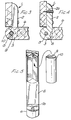
- a hinge (1) comprises a plate portion (2) and a nose portion (3) having a hollow central passageway (4) for receiving a hinge pin (5) which is used to attach a door (6) to a frame (7).
- the plate portion (2) of the hinge is apertured at 2a so that it can be screwed onto the frame (7) so that the nose portion (3) of the hinge (1) protrudes from frame (7).
- the door (6) normally has two apertures (8) formed in its edge region, each for receiving the nose portion (3) of a hinge and for each aperture (8) a recess (9) is formed in the door, normally one at the bottom and one at the top of the door, which passes through the respective aperture (8), for receiving a hinge pin (5).
- the cross sectional shape of the edge region of the door (6) corresponds to that of the nose portion (3) of the hinge (1), and the dimensions of each aperture (8) in the door edge region corresponds with that of the nose portion (3) of the hinge (1), so that, in use, the nose portion (3) fits snugly with its aperture (8).
- the door (6) also has a removable segment (10) associated with each aperture (8) which normally extends just from the aperture (8) to the top and bottom edges, respectively of the door (6). This segment allows each hinge to be fitted to the door (8).
- each segment (10) is removed from the door (6), and the nose portion (3) of the hinge is then located within the aperture (8) of the door (6).
- a hinge pin (5) is then inserted from the end of the door into the recess (9) and through the passageway (4) of the hinge, with the leading end of the hinge pin locating in the lower part of the recess (9a) to hold the door (6) and the hinge together.
- the removable segment (10) which has a portion removed to provide room for the hinge pin (5), is then secured, e.g. glued back in place and covers the trailing end of the hinge pin (5) in recess (9), thereby securing the hinge (1) in place.
- the door (6) is attached to the frame (7) by locating it correctly in place, placing the plate portions (2) against the face of the frame (7), and securing it in place, e.g. with screws which are passed through the aperture (2a) or in another known manner. Due to the nature of the hinges, the plate portions (2) need not be recessed into the frame (7).
Landscapes
- Engineering & Computer Science (AREA)
- Mechanical Engineering (AREA)
- Civil Engineering (AREA)
- Structural Engineering (AREA)
- Hinges (AREA)
Applications Claiming Priority (2)
| Application Number | Priority Date | Filing Date | Title |
|---|---|---|---|
| GB9605081A GB2311093B (en) | 1996-03-11 | 1996-03-11 | Hinge |
| GB9605081 | 1996-03-11 |
Publications (1)
| Publication Number | Publication Date |
|---|---|
| EP0795670A1 true EP0795670A1 (de) | 1997-09-17 |
Family
ID=10790176
Family Applications (1)
| Application Number | Title | Priority Date | Filing Date |
|---|---|---|---|
| EP97301570A Withdrawn EP0795670A1 (de) | 1996-03-11 | 1997-03-10 | Scharnier |
Country Status (2)
| Country | Link |
|---|---|
| EP (1) | EP0795670A1 (de) |
| GB (1) | GB2311093B (de) |
Citations (1)
| Publication number | Priority date | Publication date | Assignee | Title |
|---|---|---|---|---|
| EP0199692A1 (de) * | 1985-04-26 | 1986-10-29 | Ab Volvo | Türscharnier für Kraftfahrzeuge und dergleichen |
Family Cites Families (8)
| Publication number | Priority date | Publication date | Assignee | Title |
|---|---|---|---|---|
| GB195187A (en) * | 1922-01-10 | 1923-03-29 | Walter Morris | Improvements in hinges for automobile and other carriage doors |
| GB1116822A (en) * | 1965-11-20 | 1968-06-12 | Nieder Pietro | Improvements in or relating to doors or windows |
| US3813836A (en) * | 1972-08-21 | 1974-06-04 | Sanymetal Products Co | Toilet compartment for physically handicapped |
| GB1595703A (en) * | 1978-05-30 | 1981-08-19 | Simplifit Holdings Pty Ltd | Hinges |
| DE3401252A1 (de) * | 1984-01-16 | 1985-07-18 | Lunke & Sohn Gmbh, 5810 Witten | Demontierbares kfz-tuerscharnier |
| DE8603912U1 (de) * | 1986-02-14 | 1986-04-03 | Lange, Jürgen, Prof., 7031 Grafenau | Möbel |
| GB2192666B (en) * | 1986-07-15 | 1989-12-13 | Perstorp Ab | Improvements in or relating to a nestable-stackable container |
| GB8618669D0 (en) * | 1986-07-31 | 1986-09-10 | Nouveaux Security Products Ltd | Door & hinge construction |
-
1996
- 1996-03-11 GB GB9605081A patent/GB2311093B/en not_active Expired - Fee Related
-
1997
- 1997-03-10 EP EP97301570A patent/EP0795670A1/de not_active Withdrawn
Patent Citations (1)
| Publication number | Priority date | Publication date | Assignee | Title |
|---|---|---|---|---|
| EP0199692A1 (de) * | 1985-04-26 | 1986-10-29 | Ab Volvo | Türscharnier für Kraftfahrzeuge und dergleichen |
Also Published As
| Publication number | Publication date |
|---|---|
| GB2311093A (en) | 1997-09-17 |
| GB9605081D0 (en) | 1996-05-08 |
| GB2311093B (en) | 1999-09-15 |
Similar Documents
| Publication | Publication Date | Title |
|---|---|---|
| US4304027A (en) | Horizontally adjustable door hinge | |
| CA2351776C (en) | Bifold door fitting | |
| EP0620347B1 (de) | Scharnieraufbau mit Drehzapfen | |
| US4012868A (en) | Prehung door assembly | |
| US3006039A (en) | Concealed door hinge | |
| US4154492A (en) | Knock-down furniture system | |
| US5327616A (en) | Cabinet hinge | |
| US5392565A (en) | Door frame and gusset system | |
| CA1125463A (en) | Concealed hinge for doors, flaps, or the like | |
| US5454144A (en) | Furniture hinge including base plate with claw member | |
| US20020095971A1 (en) | Tool and method for straightening a door hinge | |
| EP0233021B1 (de) | Drehzapfenlagerblock für Falttüren | |
| EP0795670A1 (de) | Scharnier | |
| US5930883A (en) | Cabinet system and method for manufacturing cabinets | |
| US5005256A (en) | Structure of hinge | |
| ATA38696A (de) | Türflügel-anschlagteil für möbelscharniere | |
| US3813730A (en) | Hinges for use on folding doors and the like | |
| US6430778B1 (en) | Apparatus for hingedly connecting a cabinet door to a cabinet wall of a frameless cabinet | |
| US6422672B1 (en) | Frameless appliance garage adapter | |
| EP0079873A1 (de) | Innenausbauteil | |
| US4937915A (en) | Hinge | |
| GB2126636A (en) | Kit of parts for assembly into rectangular frame structures | |
| PT940540E (pt) | Charneira para portas janelas ou elementos similares | |
| US6834415B2 (en) | Concealed hinge and method of installation | |
| GB2105778A (en) | Horizontally adjustable door hinge |
Legal Events
| Date | Code | Title | Description |
|---|---|---|---|
| PUAI | Public reference made under article 153(3) epc to a published international application that has entered the european phase |
Free format text: ORIGINAL CODE: 0009012 |
|
| AK | Designated contracting states |
Kind code of ref document: A1 Designated state(s): AT CH DE GB LI |
|
| STAA | Information on the status of an ep patent application or granted ep patent |
Free format text: STATUS: THE APPLICATION IS DEEMED TO BE WITHDRAWN |
|
| 18D | Application deemed to be withdrawn |
Effective date: 19980318 |