EP0795708A2 - Collier de serrage - Google Patents
Collier de serrage Download PDFInfo
- Publication number
- EP0795708A2 EP0795708A2 EP96112410A EP96112410A EP0795708A2 EP 0795708 A2 EP0795708 A2 EP 0795708A2 EP 96112410 A EP96112410 A EP 96112410A EP 96112410 A EP96112410 A EP 96112410A EP 0795708 A2 EP0795708 A2 EP 0795708A2
- Authority
- EP
- European Patent Office
- Prior art keywords
- grooves
- webs
- thickenings
- extensions
- base part
- Prior art date
- Legal status (The legal status is an assumption and is not a legal conclusion. Google has not performed a legal analysis and makes no representation as to the accuracy of the status listed.)
- Granted
Links
- 230000008719 thickening Effects 0.000 claims description 60
- 230000007423 decrease Effects 0.000 claims description 5
- 230000015572 biosynthetic process Effects 0.000 claims description 2
- 238000013461 design Methods 0.000 description 5
- 238000006073 displacement reaction Methods 0.000 description 5
- 238000009434 installation Methods 0.000 description 3
- 238000005259 measurement Methods 0.000 description 2
- 238000000034 method Methods 0.000 description 2
- 235000001674 Agaricus brunnescens Nutrition 0.000 description 1
- 238000013459 approach Methods 0.000 description 1
- 230000008878 coupling Effects 0.000 description 1
- 238000010168 coupling process Methods 0.000 description 1
- 238000005859 coupling reaction Methods 0.000 description 1
- 238000011161 development Methods 0.000 description 1
- 238000003780 insertion Methods 0.000 description 1
- 230000037431 insertion Effects 0.000 description 1
- 239000002562 thickening agent Substances 0.000 description 1
Images


Classifications
-
- F—MECHANICAL ENGINEERING; LIGHTING; HEATING; WEAPONS; BLASTING
- F16—ENGINEERING ELEMENTS AND UNITS; GENERAL MEASURES FOR PRODUCING AND MAINTAINING EFFECTIVE FUNCTIONING OF MACHINES OR INSTALLATIONS; THERMAL INSULATION IN GENERAL
- F16L—PIPES; JOINTS OR FITTINGS FOR PIPES; SUPPORTS FOR PIPES, CABLES OR PROTECTIVE TUBING; MEANS FOR THERMAL INSULATION IN GENERAL
- F16L3/00—Supports for pipes, cables or protective tubing, e.g. hangers, holders, clamps, cleats, clips, brackets
- F16L3/22—Supports for pipes, cables or protective tubing, e.g. hangers, holders, clamps, cleats, clips, brackets specially adapted for supporting a number of parallel pipes at intervals
- F16L3/222—Supports for pipes, cables or protective tubing, e.g. hangers, holders, clamps, cleats, clips, brackets specially adapted for supporting a number of parallel pipes at intervals having single supports directly connected together
-
- F—MECHANICAL ENGINEERING; LIGHTING; HEATING; WEAPONS; BLASTING
- F16—ENGINEERING ELEMENTS AND UNITS; GENERAL MEASURES FOR PRODUCING AND MAINTAINING EFFECTIVE FUNCTIONING OF MACHINES OR INSTALLATIONS; THERMAL INSULATION IN GENERAL
- F16L—PIPES; JOINTS OR FITTINGS FOR PIPES; SUPPORTS FOR PIPES, CABLES OR PROTECTIVE TUBING; MEANS FOR THERMAL INSULATION IN GENERAL
- F16L3/00—Supports for pipes, cables or protective tubing, e.g. hangers, holders, clamps, cleats, clips, brackets
- F16L3/08—Supports for pipes, cables or protective tubing, e.g. hangers, holders, clamps, cleats, clips, brackets substantially surrounding the pipe, cable or protective tubing
- F16L3/12—Supports for pipes, cables or protective tubing, e.g. hangers, holders, clamps, cleats, clips, brackets substantially surrounding the pipe, cable or protective tubing comprising a member substantially surrounding the pipe, cable or protective tubing
- F16L3/13—Supports for pipes, cables or protective tubing, e.g. hangers, holders, clamps, cleats, clips, brackets substantially surrounding the pipe, cable or protective tubing comprising a member substantially surrounding the pipe, cable or protective tubing and engaging it by snap action
Definitions
- the invention relates to a clamp, in particular made of plastic, with a base part for the fixed arrangement of the clamp and a fork-like clamping part with clamping arms or similar clamping elements for clamping a pipe or a similar cylindrical long-shaped part, with the means of leaning on the base part on the side surfaces directed parallel to the pipe leadthrough of the clamping part are designed for arranging clamps with similarly designed baying means, whereby baying means consist of webs with thickened ends extending from the side of the base part and projecting from a side surface of the base part and of grooves formed in the other side surface of the base part with a groove base which is expanded in accordance with the web thickening.
- the base part is approximately cuboid.
- the longer side faces of the base part are directed transversely to the direction of a clamped pipe or the like, while the narrow base sides are directed parallel to it.
- the narrow base sides have the baying means, a groove being formed in one narrow side and a projection on the other narrow side.
- the groove is open at its ends, which emerge from the wide base surfaces.
- the web runs across the entire width of the narrow base part.
- the groove is provided with an extension in the groove base, while the web has a thickening at its free end.
- the design allows several similar clamps to be arranged next to one another and to be connected to one another by a parallel displacement of the adjacent clamps in such a way that the groove of a clamp to be attached is pushed onto a web of an already clamped clamp parallel to the direction of travel of a clamped pipe.
- groove-like and web-like guide elements can be formed on the long side surfaces of the base part, which enable it to be pushed on (transverse sliding) onto an installation rail or the like. In such known clamps, it is only possible to connect these clamps to one another by parallel displacement for the purpose of baying.
- the invention has for its object to provide a clamp of the generic type, in which a secure connection of two adjacent clamps is formed in the baying position and in which a stringing is possible in such a way that the clamps parallel to each other moved and the baying means can be brought into engagement with each other and the clamps can be moved transversely to one another and the baying means can thereby be brought into engagement with one another.
- the invention proposes that on the side surface of the base part provided with webs, a plurality of webs are formed at a distance from one another, running parallel to one another, the web cross-section being different and the cross-section of the thickenings being designed analogously to the web cross-sections, and that on the grooved side surface of the base part Correspondingly differently shaped grooves are formed, whereby in the baying position of adjacent clamps, all the thickened portions of the webs engage appropriately in all extensions of the groove bases, but at least the areas of thickened portions and extensions which are subject to tension in order to separate the adjacent clamps lie against one another.
- the multiple arrangement of webs with thickening and grooves with extensions ensures a high level of positional security in the baying position, since not only a single baying means but several baying means are available at the same time for fixing in the desired position. Due to the different dimensions of the web cross-sections, the thickening and the corresponding grooves, the manual connection of the clamps to one another is facilitated if these clamps are fed to one another transversely, so that the side surfaces of the base provided with grooves and webs are orthogonally fed to one another, for example when such clamps are guided in installation rails, which are arranged transversely to the direction of the pipes to be clamped.
- clamping of the clamps is accomplished both by threading and moving the adjacent clamps in the direction parallel to the course of a clamped tube or the like long cylindrical part, and also by transverse displacement of two clamps aligned parallel to one another.
- the groove mouths are shaped to widen.
- the thickenings are tapered towards the free end.
- the arrangement and design of the grooves with extensions and webs with thickenings is made such that their cross-sectional dimension decreases from the base surface of the base part to the base surface carrying the clamping part.
- the web with thickening which is arranged in the immediate vicinity of the base of the base part, the one with the largest cross-sectional dimension and also the associated groove, while with increasing distance from the base surface of the base part in the direction of the clamping arms of the base part, webs are included smaller cross-section, thickening with a smaller cross-section and correspondingly also grooves and extensions with a smaller cross-section are formed.
- a possibly preferred embodiment is seen in the fact that the webs with thickenings and the grooves with extensions in cross section are mushroom-shaped.
- the thickening of the webs and the widening of the grooves are shaped like a circular arc in cross section.
- the webs have thickened portions are arranged in such a way that corresponding grooves with extensions are formed between adjacent webs with thickenings by the facing web flanks and thickening flanks.
- the larger cross-section thickened protrude beyond the side alignment of the base part than the thickened cross-section thickened, so that when merging adjacent clamps, the larger cross-section thickened initially engage in the corresponding grooves before the next larger thickening of an adjacent web engages in the correspondingly dimensioned further groove and, as a result, the further thickening or thickenings of smaller dimensions at the web ends subsequently engage in the corresponding grooves.
- a certain force distribution is achieved during assembly, which is advantageous for the assembly process.
- clamps 1 made of plastic which have a base part 2 for the fixed arrangement of the clamp 1 and a fork-like clamp part with clamp arms 3 for clamping a pipe or the like.
- the base part 2 is essentially cuboid, the longer side surface of the cuboid lying in the drawing in the front and back, while the narrow side surfaces of the cuboid are oriented orthogonally to it.
- Grooves 4 are formed in the long side faces of the base part 2.
- the clamp 1 can be slid transversely with these grooves 4 on rails, for example plastic rails, which are profiled in a C-shape and which engage with their angled ends pointing towards one another in the corresponding grooves 4 of a clamp 1.
- baying means 5, 6 for baying clamps 1 with baying means of the same design.
- the baying means 5, 6 consist of webs 7 running parallel to the pipe leadthrough of the clamping part, projecting from one side surface of the base part 2 with thickened ends 8 and grooves 9 formed on the other side surface of the base part with a groove base 10 correspondingly enlarged to the web thickening
- Side surfaces of the base part 2 are provided in succession of grooves 9 and webs 7 with thickenings 8 or extensions 10.
- a plurality of webs 7 are formed at a distance from one another, running parallel to one another, the web cross section being different and the cross section of the thickenings 8 being designed differently at the web ends, analogously to the web cross sections.
- Correspondingly differently shaped grooves are formed on the side surface of the base part 2 provided with the grooves 9, the groove width of which decreases in accordance with the web measurement and the extension 10 of which also decreases in accordance with the thickening dimension.
- Such clamps 1 can be lined up by threading and displacing the adjacent clamps 1 in the direction parallel to the course of a clamped pipe or the like, as well as by transverse displacement of two clamps aligned parallel to one another.
- the mouths of the grooves 9 are preferably widened in the same way as the thickenings 8 are tapered towards their free ends, in order to achieve an insertion aid when connecting the baying means.
- webs 7 with thickenings 8 and grooves 9 with extensions 10 are alternately formed one above the other on both side surfaces of the base 2.
- the arrangement and design of the grooves 9 with extensions 10 and webs 7 with thickenings 8 is made such that their cross-sectional dimension decreases from the base surface (in the drawing figures 1 and 2 below) of the base part 2 to the base surface carrying the clamping part.
- the webs 7 with thickenings 8 and the grooves 9 with extensions 10 are formed like mushrooms in the embodiment according to FIG.
- the thickenings 8 of the webs 7 and the extensions 10 of the grooves 9 are shaped like a circular arc in cross section.
- the webs 7 with thickenings 8 are arranged such that between adjacent webs 7 with Thickenings 8 are formed by the mutually facing web flanks and corresponding grooves 9 with extensions 10.
- the mutually adjacent webs 7 with thickening 8 and grooves 9 with extensions 10 are formed such that when a further clamp 1 is passed transversely to an existing clamp 1, the thickening 8 with the largest cross section is first integrated into the largest dimensioned grooves 9 with extensions 10 can be partially pressed in before the thickening 8 with the next smallest cross section engages in the associated groove 9.
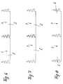
- FIGS. 3 to 8 The corresponding sequence of movements in the transverse guidance of two clamps is explained with reference to FIGS. 3 to 8.
- FIG. 3 for example, the clamp 1 shown on the left is already permanently installed, while the clamp 1 shown on the right is fed to it transversely.
- FIG. 3 for example, the clamp 1 shown on the left is already permanently installed, while the clamp 1 shown on the right is fed to it transversely.
- the invention is not limited to the exemplary embodiment, but is variable in many ways within the scope of the disclosure.
Landscapes
- Engineering & Computer Science (AREA)
- General Engineering & Computer Science (AREA)
- Mechanical Engineering (AREA)
- Clamps And Clips (AREA)
- Supports For Pipes And Cables (AREA)
- Hand Tools For Fitting Together And Separating, Or Other Hand Tools (AREA)
Applications Claiming Priority (2)
| Application Number | Priority Date | Filing Date | Title |
|---|---|---|---|
| DE19609440A DE19609440C1 (de) | 1995-11-01 | 1996-03-11 | Klemmschelle |
| DE19609440 | 1996-03-11 |
Publications (3)
| Publication Number | Publication Date |
|---|---|
| EP0795708A2 true EP0795708A2 (fr) | 1997-09-17 |
| EP0795708A3 EP0795708A3 (fr) | 1999-06-09 |
| EP0795708B1 EP0795708B1 (fr) | 2001-04-18 |
Family
ID=7787902
Family Applications (1)
| Application Number | Title | Priority Date | Filing Date |
|---|---|---|---|
| EP19960112410 Expired - Lifetime EP0795708B1 (fr) | 1996-03-11 | 1996-08-01 | Collier de serrage |
Country Status (3)
| Country | Link |
|---|---|
| EP (1) | EP0795708B1 (fr) |
| ES (1) | ES2157375T3 (fr) |
| PT (1) | PT795708E (fr) |
Cited By (2)
| Publication number | Priority date | Publication date | Assignee | Title |
|---|---|---|---|---|
| EP1746321A1 (fr) | 2005-07-22 | 2007-01-24 | IMET S.r.l. | Dispositif de fixation pour éléments cylindriques, en particulier tubes ou câbles |
| NL2022976B1 (en) * | 2019-04-18 | 2020-10-26 | Hemmink B V | Saddle clamp |
Family Cites Families (3)
| Publication number | Priority date | Publication date | Assignee | Title |
|---|---|---|---|---|
| US4306697A (en) * | 1980-06-16 | 1981-12-22 | Mathews Lyle H | Conduit spacer system |
| DE9201892U1 (de) * | 1992-02-14 | 1992-04-02 | Hermann Kleinhuis GmbH & Co KG, 5880 Lüdenscheid | Rohrschnappschelle für Elektroinstallationsrohre |
| DE9314862U1 (de) * | 1993-09-30 | 1994-01-20 | Reiku GmbH, 51674 Wiehl | Haltersystem für Rohre o.dgl. |
-
1996
- 1996-08-01 EP EP19960112410 patent/EP0795708B1/fr not_active Expired - Lifetime
- 1996-08-01 ES ES96112410T patent/ES2157375T3/es not_active Expired - Lifetime
- 1996-08-01 PT PT96112410T patent/PT795708E/pt unknown
Cited By (2)
| Publication number | Priority date | Publication date | Assignee | Title |
|---|---|---|---|---|
| EP1746321A1 (fr) | 2005-07-22 | 2007-01-24 | IMET S.r.l. | Dispositif de fixation pour éléments cylindriques, en particulier tubes ou câbles |
| NL2022976B1 (en) * | 2019-04-18 | 2020-10-26 | Hemmink B V | Saddle clamp |
Also Published As
| Publication number | Publication date |
|---|---|
| EP0795708A3 (fr) | 1999-06-09 |
| PT795708E (pt) | 2001-07-31 |
| EP0795708B1 (fr) | 2001-04-18 |
| ES2157375T3 (es) | 2001-08-16 |
Similar Documents
| Publication | Publication Date | Title |
|---|---|---|
| DE19831145C1 (de) | Gitterkabelrinne | |
| CH618251A5 (fr) | ||
| WO1990007652A2 (fr) | Dispositif d'assemblage rapide | |
| DE3221676A1 (de) | Vorrichtung zur wechselseitigen verbindung zweier teile vor deren gelegentlichem ausbau | |
| DE3636412C2 (de) | Verbindung stirnseitig einander gegenüber angeordneter Kabelkanäle | |
| DE69600062T2 (de) | Elektrischer Verbinder | |
| WO2019007546A1 (fr) | Moyen de guidage de câble destiné à être disposé sur une tige profilée | |
| DE3643641C1 (de) | Binder mit einstueckig angeformtem Arretierkopf aus Kunststoff | |
| DE19609440C1 (de) | Klemmschelle | |
| EP0977582A1 (fr) | Preparations pharmaceutiques associees contenant de l'erythropoietine et preparations a base de fer | |
| EP0139980B1 (fr) | Cable clamp | |
| DE3879353T2 (de) | Verbindungsanordnung aus einer profilsektion. | |
| EP0795708B1 (fr) | Collier de serrage | |
| DE19903972C2 (de) | Federmutter zur Schnellbefestigung | |
| EP0724104A1 (fr) | Elément d'atténuation de contraintes et de fixation | |
| EP0693638B1 (fr) | Chaine de support d'au moins un conducteur d'énergie et procédé d'introduction du conducteur dans la chaine | |
| DE2943578C2 (de) | Anschlußleiste | |
| EP1229282A2 (fr) | Adaptateur pour le montage de collier de fixation | |
| DE2453754C2 (de) | Schleifleitungsanordnung | |
| EP1596076B1 (fr) | Dispositiv de fixation d'au moins deux pièces, utilisation et un procede de ce dispositiv | |
| DE69312230T2 (de) | Kupplungseinrichtung für Kabelrinneteilen | |
| DE19817427A1 (de) | Klemmverbinder | |
| EP1255339A1 (fr) | Pince d'ancrage à cale sans vis | |
| DE3729276C2 (fr) | ||
| DE4303935A1 (de) | Kreuzverbinder |
Legal Events
| Date | Code | Title | Description |
|---|---|---|---|
| PUAI | Public reference made under article 153(3) epc to a published international application that has entered the european phase |
Free format text: ORIGINAL CODE: 0009012 |
|
| AK | Designated contracting states |
Kind code of ref document: A2 Designated state(s): BE ES IT LU NL PT |
|
| PUAL | Search report despatched |
Free format text: ORIGINAL CODE: 0009013 |
|
| AK | Designated contracting states |
Kind code of ref document: A3 Designated state(s): BE ES IT LU NL PT |
|
| 17P | Request for examination filed |
Effective date: 19990617 |
|
| RAP1 | Party data changed (applicant data changed or rights of an application transferred) |
Owner name: OBO BETTERMANN GMBH & CO. KG. |
|
| GRAG | Despatch of communication of intention to grant |
Free format text: ORIGINAL CODE: EPIDOS AGRA |
|
| GRAG | Despatch of communication of intention to grant |
Free format text: ORIGINAL CODE: EPIDOS AGRA |
|
| GRAH | Despatch of communication of intention to grant a patent |
Free format text: ORIGINAL CODE: EPIDOS IGRA |
|
| 17Q | First examination report despatched |
Effective date: 20001012 |
|
| GRAH | Despatch of communication of intention to grant a patent |
Free format text: ORIGINAL CODE: EPIDOS IGRA |
|
| GRAA | (expected) grant |
Free format text: ORIGINAL CODE: 0009210 |
|
| AK | Designated contracting states |
Kind code of ref document: B1 Designated state(s): BE ES IT LU NL PT |
|
| ITF | It: translation for a ep patent filed | ||
| REG | Reference to a national code |
Ref country code: PT Ref legal event code: SC4A Free format text: AVAILABILITY OF NATIONAL TRANSLATION Effective date: 20010424 |
|
| PG25 | Lapsed in a contracting state [announced via postgrant information from national office to epo] |
Ref country code: LU Free format text: LAPSE BECAUSE OF EXPIRATION OF PROTECTION Effective date: 20010801 |
|
| REG | Reference to a national code |
Ref country code: ES Ref legal event code: FG2A Ref document number: 2157375 Country of ref document: ES Kind code of ref document: T3 |
|
| PLBE | No opposition filed within time limit |
Free format text: ORIGINAL CODE: 0009261 |
|
| STAA | Information on the status of an ep patent application or granted ep patent |
Free format text: STATUS: NO OPPOSITION FILED WITHIN TIME LIMIT |
|
| 26N | No opposition filed | ||
| PGFP | Annual fee paid to national office [announced via postgrant information from national office to epo] |
Ref country code: NL Payment date: 20140820 Year of fee payment: 19 |
|
| PGFP | Annual fee paid to national office [announced via postgrant information from national office to epo] |
Ref country code: ES Payment date: 20140826 Year of fee payment: 19 |
|
| PGFP | Annual fee paid to national office [announced via postgrant information from national office to epo] |
Ref country code: PT Payment date: 20140203 Year of fee payment: 19 Ref country code: IT Payment date: 20140828 Year of fee payment: 19 |
|
| PGFP | Annual fee paid to national office [announced via postgrant information from national office to epo] |
Ref country code: BE Payment date: 20140820 Year of fee payment: 19 |
|
| REG | Reference to a national code |
Ref country code: PT Ref legal event code: MM4A Free format text: LAPSE DUE TO NON-PAYMENT OF FEES Effective date: 20160201 |
|
| PG25 | Lapsed in a contracting state [announced via postgrant information from national office to epo] |
Ref country code: IT Free format text: LAPSE BECAUSE OF NON-PAYMENT OF DUE FEES Effective date: 20150801 |
|
| REG | Reference to a national code |
Ref country code: NL Ref legal event code: MM Effective date: 20150901 |
|
| PG25 | Lapsed in a contracting state [announced via postgrant information from national office to epo] |
Ref country code: PT Free format text: LAPSE BECAUSE OF NON-PAYMENT OF DUE FEES Effective date: 20160201 |
|
| PG25 | Lapsed in a contracting state [announced via postgrant information from national office to epo] |
Ref country code: NL Free format text: LAPSE BECAUSE OF NON-PAYMENT OF DUE FEES Effective date: 20150901 |
|
| REG | Reference to a national code |
Ref country code: ES Ref legal event code: FD2A Effective date: 20160927 |
|
| PG25 | Lapsed in a contracting state [announced via postgrant information from national office to epo] |
Ref country code: ES Free format text: LAPSE BECAUSE OF NON-PAYMENT OF DUE FEES Effective date: 20150802 Ref country code: PT Free format text: LAPSE BECAUSE OF EXPIRATION OF PROTECTION Effective date: 20160809 |
|
| PG25 | Lapsed in a contracting state [announced via postgrant information from national office to epo] |
Ref country code: BE Free format text: LAPSE BECAUSE OF NON-PAYMENT OF DUE FEES Effective date: 20150831 Ref country code: PT Free format text: LAPSE BECAUSE OF EXPIRATION OF PROTECTION Effective date: 20160208 |