EP0795725A2 - Adsorptionskältegerät - Google Patents
Adsorptionskältegerät Download PDFInfo
- Publication number
- EP0795725A2 EP0795725A2 EP97104410A EP97104410A EP0795725A2 EP 0795725 A2 EP0795725 A2 EP 0795725A2 EP 97104410 A EP97104410 A EP 97104410A EP 97104410 A EP97104410 A EP 97104410A EP 0795725 A2 EP0795725 A2 EP 0795725A2
- Authority
- EP
- European Patent Office
- Prior art keywords
- stage
- adsorption
- stages
- heat exchanging
- coolant fluid
- Prior art date
- Legal status (The legal status is an assumption and is not a legal conclusion. Google has not performed a legal analysis and makes no representation as to the accuracy of the status listed.)
- Granted
Links
- 238000005057 refrigeration Methods 0.000 title claims description 36
- 238000001179 sorption measurement Methods 0.000 claims abstract description 546
- 239000012530 fluid Substances 0.000 claims abstract description 270
- 239000002826 coolant Substances 0.000 claims abstract description 231
- 239000003507 refrigerant Substances 0.000 claims abstract description 170
- 239000003463 adsorbent Substances 0.000 claims abstract description 117
- 238000000034 method Methods 0.000 claims abstract description 115
- 230000008569 process Effects 0.000 claims abstract description 115
- 238000003795 desorption Methods 0.000 claims abstract description 66
- 238000010438 heat treatment Methods 0.000 claims description 56
- 238000001816 cooling Methods 0.000 claims description 37
- 238000001704 evaporation Methods 0.000 claims description 21
- 239000002245 particle Substances 0.000 claims description 14
- OKTJSMMVPCPJKN-UHFFFAOYSA-N Carbon Chemical compound [C] OKTJSMMVPCPJKN-UHFFFAOYSA-N 0.000 claims description 11
- 239000003795 chemical substances by application Substances 0.000 claims description 11
- LFQSCWFLJHTTHZ-UHFFFAOYSA-N Ethanol Chemical compound CCO LFQSCWFLJHTTHZ-UHFFFAOYSA-N 0.000 claims description 10
- 239000000126 substance Substances 0.000 claims description 8
- 230000007423 decrease Effects 0.000 claims description 3
- 230000008014 freezing Effects 0.000 claims description 3
- 238000007710 freezing Methods 0.000 claims description 3
- 238000004378 air conditioning Methods 0.000 abstract description 45
- XLYOFNOQVPJJNP-UHFFFAOYSA-N water Substances O XLYOFNOQVPJJNP-UHFFFAOYSA-N 0.000 description 33
- 239000003570 air Substances 0.000 description 29
- 239000007788 liquid Substances 0.000 description 25
- 230000008020 evaporation Effects 0.000 description 18
- 238000002156 mixing Methods 0.000 description 17
- 238000009834 vaporization Methods 0.000 description 10
- 230000008016 vaporization Effects 0.000 description 10
- 238000001879 gelation Methods 0.000 description 8
- 238000009833 condensation Methods 0.000 description 5
- 230000005494 condensation Effects 0.000 description 5
- 230000000694 effects Effects 0.000 description 5
- 238000004519 manufacturing process Methods 0.000 description 5
- 238000005260 corrosion Methods 0.000 description 4
- 230000007797 corrosion Effects 0.000 description 4
- 239000000203 mixture Substances 0.000 description 4
- 230000009467 reduction Effects 0.000 description 4
- VYPSYNLAJGMNEJ-UHFFFAOYSA-N Silicium dioxide Chemical compound O=[Si]=O VYPSYNLAJGMNEJ-UHFFFAOYSA-N 0.000 description 2
- 230000001276 controlling effect Effects 0.000 description 2
- 238000007791 dehumidification Methods 0.000 description 2
- 238000010586 diagram Methods 0.000 description 2
- 239000012153 distilled water Substances 0.000 description 2
- 230000004048 modification Effects 0.000 description 2
- 238000012986 modification Methods 0.000 description 2
- 230000005855 radiation Effects 0.000 description 2
- 239000000741 silica gel Substances 0.000 description 2
- 229910002027 silica gel Inorganic materials 0.000 description 2
- FAPWRFPIFSIZLT-UHFFFAOYSA-M Sodium chloride Chemical compound [Na+].[Cl-] FAPWRFPIFSIZLT-UHFFFAOYSA-M 0.000 description 1
- 229910021536 Zeolite Inorganic materials 0.000 description 1
- PNEYBMLMFCGWSK-UHFFFAOYSA-N aluminium oxide Inorganic materials [O-2].[O-2].[O-2].[Al+3].[Al+3] PNEYBMLMFCGWSK-UHFFFAOYSA-N 0.000 description 1
- 239000012080 ambient air Substances 0.000 description 1
- 229910052799 carbon Inorganic materials 0.000 description 1
- 230000001143 conditioned effect Effects 0.000 description 1
- 239000012809 cooling fluid Substances 0.000 description 1
- 230000003111 delayed effect Effects 0.000 description 1
- HNPSIPDUKPIQMN-UHFFFAOYSA-N dioxosilane;oxo(oxoalumanyloxy)alumane Chemical compound O=[Si]=O.O=[Al]O[Al]=O HNPSIPDUKPIQMN-UHFFFAOYSA-N 0.000 description 1
- 230000002349 favourable effect Effects 0.000 description 1
- 230000001105 regulatory effect Effects 0.000 description 1
- 239000011780 sodium chloride Substances 0.000 description 1
- 239000010457 zeolite Substances 0.000 description 1
Images








Classifications
-
- F—MECHANICAL ENGINEERING; LIGHTING; HEATING; WEAPONS; BLASTING
- F25—REFRIGERATION OR COOLING; COMBINED HEATING AND REFRIGERATION SYSTEMS; HEAT PUMP SYSTEMS; MANUFACTURE OR STORAGE OF ICE; LIQUEFACTION SOLIDIFICATION OF GASES
- F25B—REFRIGERATION MACHINES, PLANTS OR SYSTEMS; COMBINED HEATING AND REFRIGERATION SYSTEMS; HEAT PUMP SYSTEMS
- F25B17/00—Sorption machines, plants or systems, operating intermittently, e.g. absorption or adsorption type
- F25B17/08—Sorption machines, plants or systems, operating intermittently, e.g. absorption or adsorption type the absorbent or adsorbent being a solid, e.g. salt
Definitions
- This invention relates to an adsorptive-type refrigeration apparatus for performing adsorption of refrigerant vaporized in an evaporator by chilling and heating of an adsorbent held by an adsorption device and for supplying refrigerant vapor to a condenser.
- An adsorptive-type refrigeration apparatus which adsorbs refrigerant vapor vaporized by an evaporator by chilling adsorbent, and which desorbs refrigerant and supplies the same to a condenser by switching adsorbent to a heated state is known in the art.
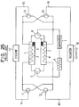
- FIG. 25 adsorbent S and heat exchanging passages 3 and 4 are provided within first and second adsorption devices 1 and 2, and refrigerant outlets of these first and second adsorption devices 1 and 2 are connected via a three-way valve 5 to a condenser 6. Accordingly, the condenser 6 is connected to an evaporator 7, and the evaporator 7 further is connected via a three-way valve 8 to refrigerant inlets of the first and second adsorption devices 1 and 2.
- a heating fluid supply pipe 9 and a coolant fluid supply pipe 10 are connected via three-way valves 11 and 12 to inlets of the heat exchanging passages 3 and 4, and outlets of the heat exchanging passages 3 and 4 are connected via three-way valves 13 and 14 to a heating fluid discharge pipe 15 and a coolant fluid discharge pipe 16.
- coolant water of an engine 17 is used as the heating fluid
- water chilled by a radiator 18 radiating heat to the atmosphere is used as the coolant fluid.
- the heating fluid supply pipe 9 and discharge pipe 15 are connected respectively to a coolant water outlet and a coolant water inlet of the engine 17, and the coolant fluid supply pipe 10 and discharge pipe 16 are connected respectively to an outlet and an inlet of the radiator 18.
- heating fluid passes through the supply pipe 9, the three-way valve 11, the heat exchanging passage 3 of the first adsorption device 1, and the three-way valve 13, and is discharged from the discharge pipe 15.
- the coolant fluid passes through the supply pipe 10, the three-way valve 12, the heat exchanging passage 4 of the second adsorption device 2, and the three-way valve 14, and is discharged from the discharge pipe 16.
- the adsorbent S within the first adsorption device 1 is heated by the heating fluid passing through the heat exchanging passage 3, and refrigerant which had been adsorbed thereto evaporates and is desorbed.
- This refrigerant vapor enters the condenser 6 via the three-way valve 5; herein, it exchanges heat with an external volume and is condensed, thereby becoming refrigerant liquid.
- Refrigerant liquid discharged from the condenser 6 is supplied to the evaporator 7, where it exchanges heat with an external area and is vaporized.
- the refrigerant vapor vaporised by the evaporator 7 passes through the three-way valve 8, enters the second adsorption device 2, and is adsorbed to the adsorbent S. Heat generated at the time of this adsorption of refrigerant vapor is usurped by coolant fluid flowing through the heat exchanging passage 4.
- the three-way valves 5, 8, and 11 through 14 are switched from the state shown by solid lines to the state shown by broken lines.
- the three-way valves 5, 8, and 11 through 14 are switched from the state shown by broken lines to the state shown by solid lines; thereafter, similarly to the foregoing, the first and second adsorption devices 1 and 2 alternately repeat an adsorption process and a desorption process.
- a pair of adsorption devices are provided in only one stage to alternately supply coolant fluid cooled by heat radiation of the radiator 18 and heating fluid (engine coolant water) heated by cooling the engine 17 to cause these paired adsorption devices to alternately execute an adsorption process and a desorption process.
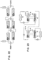
- an adsorptive-type refrigeration apparatus disclosed in Japanese Patent Application Laid-Open Publication No. Hei 7-120100 has a mode providing adsorption devices in multiple stages. As shown in FIG. 24, in this system an interior of a reactor 22 provided with adsorbent S and a heat exchanging passage 21 is partitioned into a plurality of chambers C1 through C7.
- This apparatus is provided with valves V1 through V7 and V8 through V14 for opening and closing an interval between the several chambers C1 through C7 and a condenser 24 or an evaporator 25.
- the heat transmitting fluid flows from the heat source 25 through the heat exchanging passage 21 to a cooling and heating source 26 in a state wherein the valves V1 through V7 are open and the valves V8 through V14 are closed; during the adsorption process, conversely, the heat transmitting fluid flows from the cooling and heating source 26 through the heat exchanging passage 21 to the heat source 25 in a state where the valves V8 through V14 are open and the valves V1 through V7 are closed.
- the open or closed states of the valves V1 through V14 are controlled in the following way. Namely, in a state where the desorption process has ended, the valves V1 through V7 for connecting the several chambers C1 through C7 to the condenser 24 are all opened and the valves V8 through V14 for connecting the several chambers C1 through C7 to the evaporator 25 are all closed.
- the valve V1 on the condenser 24 side of the first stage chamber C1 is closed, compressing a piston 27 of the cooling and heating source 26, and chilled heat transmitting fluid passes through the heat exchanging passage 21 and is allowed to flow toward the heat source 25.
- cooling of the first stage chamber C1 begins, and pressure thereof declines.
- the valve V8 on the evaporator 24 side of the first stage chamber C1 is opened, and simultaneously thereto, the valve V2 on the condenser 23 side of the second stage chamber C2 is closed.
- valves V3 through V7 are successively closed, and along with this, the valves V10 through V14 are successively opened, and ultimately the valves V1 through V7 on the condenser 23 are all opened and the valves V8 through V14 on the evaporator 24 side are all closed.
- valves V1 through V14 By controlling the valves V1 through V14 in this way, it becomes possible to obtain a steep temperature front, and an attempt is made to preheat the heat transmitting fluid by liquefaction latent heat of the adsorbent S and boost thermal efficiency when switching from the adsorption process to the desorption process, and along with this, to increase desorption efficiency.
- heating fluid engine coolant water
- water cooled by a radiator 18 which radiates heat to the atmosphere must perforce be employed, as was described with reference to FIG. 25, and as a result thereof, coolant fluid of sufficiently low temperature cannot be obtained.
- an object of the present invention to provide an adsorptive-type refrigeration apparatus which can amply exhibit adsorption capacity of adsorbent and can demonstrate high cooling capacity.
- the above object is achieved according to a first aspect of the present invention by providing an adsorptive-type refrigeration apparatus in which multiple stages of evaporators and adsorption devices are provided in a one-to-one relationship to supply coolant fluid cooled by the evaporators to a heat exchanging passage of an adsorption device of a prior stage.
- heat exchanging passages of at least two mutually adjacent stages of adsorption devices among the plurality of stages of adsorption devices are connected in series, or passages of coolant fluid chilled by at least mutually adjacent evaporators among the plurality of stages of evaporators are connected in series, and so even when adsorption devices of a plurality of stages exist, the number of circulation paths to supply coolant fluid thereto can be small, and simplification of piping configuration can be accomplished.
- heat exchanging passages of several stages of adsorption devices and a radiator which radiates heat to an external volume and a plurality of heat exchangers cooled by several stages of evaporators and a cooler for cooling outside air are connected in series, and coolant fluid cooled by the radiator further is successively cooled by heat exchangers from the final stage evaporator to the first stage evaporator.
- the coolant fluid thereof firstly is supplied to a chiller to cool an external area, and thereafter is successively supplied to the heat exchanging passages from the first stage adsorption device to the final stage adsorption device, and due to this structure the circulation path of the coolant fluid can be made to be a single path.
- An adsorbent's speed of adsorbing refrigerant vapor increases as pressure becomes higher, even at identical relative humidity. Because evaporation pressure of refrigerant adsorbed by the plurality of stages of adsorption devices becomes increasingly higher at successively later stages, adsorption speed is increasingly faster for adsorbent at successively later stages. Because of this, compactness of the adsorption device can be achieved by reducing the filled quantity of adsorbent in adsorption devices at increasingly later stages among the plurality of stages of adsorption devices, and moreover there is no danger of loss in adsorption capacity of refrigerant even when such compactness is realized.
- the condenser may be multiply provided to correspond to the several stages of evaporators and adsorption devices, so that a circulating system of refrigerant is independently established for each of the several stages, and among refrigerant sealed within these several stages of condensers, evaporators, and adsorption devices, a gelation point lowering agent is intermixed in refrigerant of a required stage of a forward stage side. Because of this, usage of a gelation point lowering agent with which there exists a chance of bringing about problems such as a reduction of cooling capacity, corrosion, or the like can be restricted to a minimal range on the front stage side.
- a required stage of a forward stage side may employ an alcohol-based substance as refrigerant and may employ activated carbon as adsorbent to adsorb.
- freezing of the refrigerant can reliably be prevented because the temperature at which the alcohol-based substance freezes is low, and smaller quantities of adsorbent can be used because the activated carbon readily adsorbs the alcohol-based substance.
- the heat exchanging passages of the several stages of adsorption devices when viewed all together, make up a counterflow heat exchanger.
- coolant fluid discharged from the radiator and coolant fluid discharged from the cooler are intermixed and supplied to a heat exchanger of the final stage evaporator and a heat exchanging passage of the first stage adsorption device
- temperature of coolant fluid flowing into the heat exchanging passage of the first stage adsorption device becomes high, and so the amount of head dissipated during refrigerant adsorption of the adsorbent is reduced, and heat exchange efficiency is heightened.
- the stages of adsorption devices are disposed in pairs, and each pair of adsorption devices alternately execute an adsorbing process and a desorbing process through a relationship wherein when one performs adsorption through coolant fluid being supplied to its heat exchanging passage, another performs desorption through heating fluid being supplied to its heat exchanging passage, and when these processes are switched, after the heat exchanging passages of several stages of adsorption devices have passed through a state wherein adsorption device heat exchanging passages in which an execution process prior to switching and an execution process subsequent to switching are identical are connected in series, adsorption device heat exchanging passages wherein an identical process is executed subsequently to switching are connected in series.
- coolant fluid or heating fluid remaining within the several stages of heat exchanging passages at a time of process switching is supplied the heat exchanging passage of the adsorption device which executes the adsorption process or desorption process after switching, and so time interval until an adsorption device in particular on a later stage side reaches a state where adsorption or desorption can actually be performed is short.
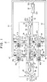
- FIGS. 1-4 show a first preferred embodiment of the present invention.
- This embodiment is provided with two stages of evaporators and adsorption devices, and the adsorption devices of the respective stages are made up of two adsorption devices to alternately repeat a desorption process and an adsorption process through a relationship where while one is performing the desorption process, the other is executing the adsorption process.
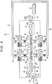
- FIGS. 1 and 2 show an overall system structure of an adsorptive-type refrigeration apparatus 31 in mutually differing states.
- This adsorptive-type refrigeration apparatus 31 includes, for example, one condenser 32, a first stage evaporator 33, a second stage evaporator 34, first and second first stage adsorption devices 35 and 36 corresponding to the first stage condenser 33, and first and second second stage adsorption devices 37 and 38 corresponding to the second stage evaporator 34. These are disposed in the car's engine compartment.
- the condenser 32 condenses refrigerant vapor supplied through an inlet 32a, and discharges the condensed vapor as liquid refrigerant from an outlet 32b.
- the respective evaporators 33 and 34 evaporate refrigerant liquid supplied to inlets 33a and 34a, and discharge the evaporant from outlets 33b, 33c, 34b and 34c.
- the adsorption devices 35 through 38 house adsorbent S in the form of numerous particles in a receptacle, and along with this, provide heat exchanging passages 39 through 42 to perform heat exchange with this adsorbent S. Accordingly, when low temperature coolant fluid is flowing through the heat exchanging passages 39 through 42, adsorbent S cooled by this coolant fluid passes through inlets 35a through 38a and adsorbs refrigerant vapor. When high temperature heating fluid is flowing through the heat exchanging passages 39 through 42, the adsorbent S warmed by this heating fluid desorbs refrigerant, thereby causing it to become refrigerant vapor, and discharges this vapor from outlets 35b through 42b. Water, for example, is used as the refrigerant, and silica gel, zeolite, activated carbon , activated alumina, or the like is used as the adsorbent S.
- the condenser 32 and the evaporators 33 and 34 are alternately connected by a path (piping structure) as will be described below with respect to the adsorption devices 35 through 38 to adsorb and desorb refrigerant as was described above.
- a path piping structure
- the inlets 35a and 36a thereof are connected via switching valves 43 and 44 to the outlets 33b and 33c of the first stage evaporator 33.
- the inlets 37a and 38a thereof are connected to the outlets 34b and 34c of the second stage evaporator 34.
- outlets 35b through 38b of the several adsorption devices 35 through 38 are connected via outlet-side switching valves 47 through 50 to refrigerant vapor passages 51 and 52, and these refrigerant vapor passages 51 and 52 are connected to the inlet 32a of the condenser 32.
- the outlet 32a of the condenser 32 is connected to the inlet 34a of the second stage evaporator 34 via a capillary tube 53 which doubles as a restrictor serving as a refrigerant liquid passage, and furthermore, the inlet 33a of the first stage evaporator 33 is connected to this second stage evaporator 34 via a capillary tube 54 serving as a refrigerant liquid passage. Due to this, refrigerant liquid condenses by the condenser 32 is supplied sequentially to the second stage evaporator 34 and the first stage evaporator 33.
- Heat exchangers 55 and 56 are disposed in an internal portion of the two evaporators 33 and 34, and heat exchanging fluid (for example, water) in an internal portion of these heat exchangers 55 and 56 is cooled by latent heat of vaporization of refrigerant liquid of the evaporators 33 and 34.
- the heat exchanger 55 of the first stage evaporator 33 is for external area cooling use, i.e., is used to cool air blown in a passenger compartment of a car through a vent duct (not shown) of an automotive air conditioner.
- the heat exchanger 55 for external cooling use is connected via a circulation path 58 to a cooler for air conditioning use 57.
- Heat exchanging fluid cooled by latent heat of vaporization of refrigerant liquid in the first stage evaporator 33 is sent in the direction of arrow A by a pump 59 disposed in the circulation path 58 to be circulated between the heat exchanger 55 and the cooler for air conditioning use 57.
- refrigerant piping for causing refrigerant vapor which has been vaporized by the first stage evaporator 33 to be returned to the first first stage adsorption device 35 or the second first stage adsorption device 36 need not be deployed for a great length between the engine compartment in the passenger compartment in circumstances where piping of large diameter must be employed.
- the heat exchanger 56 of the second stage evaporator 34 is employed for generating coolant fluid supplied to the heat exchanging passages 39 through 42 of the adsorption devices 35 through 38.
- This heat exchanger 56 is connected in series with the radiator 60 which radiates heat to the atmosphere, and coolant fluid which has been cooled by the thermal radiation of the radiator 60 is further cooled by latent heat of vaporization of refrigerant liquid in the second stage evaporator 34.
- high temperature heating fluid may be supplied to the heat exchanging passages 29 through 42 of the adsorption devices 35 through 38, but in this embodiment, engine coolant water is used as the heating fluid.
- the heat exchanging passages 39 and 41 of the first first stage adsorption device 35 and the first second stage adsorption device 37 are connected in series, the inlet 39a of the heat exchanging passage 39 is connected to a first port 61a of an inlet-side four-way valve (4-port, 2-position value) 61, and the outlet 41a of the heat exchanging passage 41 is connected to a first port 62a of an outlet-side four-way valve (4-port, 2-position value) 62.
- the heat exchangers 40 and 42 of the second first stage adsorption device 36 and the second second stage adsorption device 38 are connected in series, the inlet 40a of the heat exchanging passage 40 is connected to a second port 61b of the inlet-side four-way valve 61, and the outlet 42b of the heat exchanging passage 42 is connected to a second port 62b of the outlet-side four-way valve 62.
- a circulation path pipe 63 and a return path pipe 64 are connected to a coolant water discharge port and intake port of the engine (not shown). Accordingly, the circulation path pipe 63 is connected to a third port 61c of the inlet-side four-way valve 61, and the return path pipe 64 is connected to a third port 62c of the outlet-side four-way valve 62.
- an outlet 56a of the heat exchanger 56 is connected to a fourth port 61d of the inlet-side four-way valve 61 via a pump 65 to send coolant fluid in the direction of arrow B, and along with this, an inlet 60a of the radiator 60 is connected to a fourth port of the four-way valve 62.
- the four-way valves 61 and 62 are structured to be switched between a first state shown in FIG. 1 and a second state shown in FIG. 2. Accordingly, in the first state, the inlet-side four-way valve 61 connects the first port 61a and the fourth port 61d, and connects the second port 61b and the third port 61c; similarly, the outlet-side four-way valve 62 as well connects the first port 62a and the fourth port 62d, and connects the second port 62b and the third port 62c.
- heating fluid discharged from the engine is circulated to flow from the heat exchanging passage 40 of the second first stage adsorption device 36 to the heat exchanging passage 42 of the second second stage adsorption device 38 and be returned to the engine, and along with this, coolant fluid cooled by the radiator 60 and the heat exchanger 56 of the second stage evaporator 34 is circulated to flow from the heat exchanging passage 39 of the first first stage adsorption device 35 to the heat exchanging passage 41 of the first second stage adsorption device 37 and be returned to the radiator 60.
- the inlet-side four-way valve 61 connects the first port 61a and the third port 61c, and connects the second port 61b and the fourth port 61d; similarly, the outlet-side four-way valve 62 as well connects the first port 62a and the third port 62c, and connects the second port 62b and the fourth port 62d.
- heating fluid discharged from the engine is circulated to flow from the heat exchanging passage 39 of the first first stage adsorption device 35 to the heat exchanging passage 41 of the first second stage adsorption device 37 and be returned to the engine, and along with this, coolant fluid cooled by the radiator 60 and the heat exchanger 56 of the second stage evaporator 34 is circulated to flow from the heat exchanging passage 40 of the second first stage adsorption device 36 to the heat exchanging passage 42 of the second second stage adsorption device 38 and be returned to the radiator 60.
- the four-way valves 61 and 62 are of the electromotive type (for example, rotary-type devices driven by a motor) and are controlled along with the above-described switching valves 43 through 50 by a controller (ECU) as a controlling device provided with a microprocessor.
- the four-way valves 61 and 62 and the switching valves 43 through 50 are controlled to switch and be actuated at every occurrence of a fixed interval (for example, 60 seconds).
- the switching period of the four-way valves 61 and 62 and the switching valves 43 through 50 is established at a time, previously determined through experimentation or theoretically, required by the adsorbent S for desorption or adsorption.
- the controller controls the two four-way valves 61 and 62 and the switching valves 43 through 50 so that when one pair among the pair made up of the first first stage adsorption device 35 and the first second stage adsorption device 37 and the pair made up of the second first stage adsorption device 36 and the second second stage adsorption device 38 is in the adsorption process, the other pair executes the desorption process.
- an open state of the switching valves 43 through 50 is shown as white, and a closed state thereof is shown as black.
- the state is taken to be such that the pair made up of the first first stage adsorption device 35 and the first second stage adsorption device 37 is taken to be in a state of executing the adsorption process, and the pair made up of the second first stage adsorption device 36 and the second second stage adsorption device 38 is executing the desorption process.
- the first first stage adsorption device 35 and the first second stage adsorption device 37 respectively communicate with the first stage evaporator 33 and the second stage evaporator 34 by opening the switching valves 43 and 45, and along with this, the condenser 32 is in a closed state due to closure of the switching valves 47 and 49, and the heat exchanging passages 39 and 41 thereof receive a supply of coolant fluid.
- the second first stage adsorption device 36 and the second second stage adsorption device 38 communicate with the condenser 32 by opening the switching valves 48 and 50, and along with this, the first stage evaporator 33 and the second stage evaporator 34 are in a closed state due to closure of the switching valves 44 and 46, and the heat exchanging passages 40 and 42 thereof receive a supply of heating fluid.
- adsorbent S of the first first stage adsorption device 35 and the first second stage adsorption device 37 is cooled and exhibits an adsorption effect, and so coolant liquid which has been collected in the first stage evaporator 33 and the second stage evaporator 34 is vaporized, and the vaporized coolant vapor is adsorbed respectively to the first first stage adsorption device 35 and the first second stage adsorption device 37. Due to the latent heat of vaporization of refrigerant of the first stage adsorption device 33 at this time, heat exchange refrigerant flowing within the heat exchanger 55 is cooled, and due to this, the cooler for air conditioning use 57 exhibits a chilling effect and chills air flowing within the vent duct.
- adsorbent S of the second first stage adsorption device 36 and the second second stage adsorption device 38 is heated by heating fluid, refrigerant which had been adsorbed to this adsorbent S is desorbed, and the refrigerant vapor produced by this desorption is supplied to the condenser 32, where it is cooled by heat exchange with the atmosphere and condenses. Accordingly, the refrigerant liquid condensed by the condenser 32 is supplied to the second stage evaporator 34 and the first stage evaporator 33, and here it is vaporized and adsorbed respectively to adsorbent S of the first first stage adsorption device 35 and the first second stage adsorption device 37.
- latent heat of condensation released from the refrigerant due to the adsorption effect of adsorbent S in the first first stage adsorption device 35 and the first second stage adsorption device 37 is usurped by coolant fluid flowing through the heat exchanging passages 39 and 41.
- Coolant fluid the temperature of which has been elevated by this usurpation of latent heat of condensation, is successively circulated first to be cooled by radiating heat to the atmosphere at the radiator 60, thereafter to be further cooled by latent heat of vaporization at the second stage evaporator 34 in the heat exchanger 56, and thereafter to flow again to the heat exchangers 39 and 41 of the first first stage adsorption device 35 and the first second stage adsorption device 37.
- the first first stage adsorption device 35 and the first second stage adsorption device 37 communicate with the condenser 32 by opening of the switching valves 47 and 49 and are cut off respectively from the first stage evaporator 33 and the second stage evaporator 34 by closing the switching valves 43 and 45, and along with this, the heat exchanging passages 39 and 41 thereof receive a supply of heating fluid.
- the second first stage adsorption device 36 and the second second stage adsorption device 38 communicate with the first stage evaporator 33 and the second stage evaporator 34 by opening the switching valves 44 and 46 and are cut off from the condenser 32 by closing the switching valves 48 and 50, and along with this, the heat exchanging passages 40 and 42 thereof receive a supply of coolant fluid.
- this state in FIG. 2 is merely a state wherein the adsorption process and the desorption process are performed by the opposite pairs of the state in FIG. 1, namely so that the pair made up of the first first stage adsorption device 35 and the first second stage adsorption device 37 performs the desorption process and the pair made up of the second first stage adsorption device 36 and the second second stage adsorption device 38 performs the adsorption process, detailed description of this state will be omitted. Accordingly, when this state in FIG. 2 has continued for a fixed time, the four-way valves 61 and 62 and the switching valves 43 through 50 are switched to the state shown in FIG. 1, and in this way the first first stage adsorption device 35 and the state of FIG. 1 and the state of FIG. 2 are alternately repeated at every occurrence of a fixed interval.
- coolant fluid cooled by the radiator 60 is further cooled by the heat exchanging passages 39 and 41 of the first first stage adsorption device 35 and the first second stage adsorption device 37 or is supplied to the heat exchanging passages 40 and 42 of the second first stage adsorption device 36 and the second second stage adsorption device 38, and so overall cooling performance of the adsorptive-type refrigeration apparatus 31 can be heightened without causing the adsorption devices 35 to 38 to be large.
- minimum adsorption rate during desorption by an adsorption device is determined by dew point temperature of the refrigerant, i.e., the condensation temperature in the condenser, and by the heating temperature of the adsorbent, i.e., the temperature of the heating fluid;
- maximum adsorption rate during adsorption by an adsorption device is determined by dew point temperature of the refrigerant, i.e., the vaporization temperature of the refrigerant fluid in the evaporator, and by the chilling temperature of the adsorbent, i.e., the temperature of the coolant fluid.
- refrigerant corresponding to the differential of this minimum adsorption rate and maximum adsorption rate is supplied to the condenser and the evaporator, and a refrigerating (cooling) effect is exhibited in the evaporator. Because of this, it can be said that the larger the difference between the minimum adsorption rate during desorption and the maximum adsorption rate during adsorption, the higher the refrigeration capacity.
- temperature of the engine coolant water which is the heating fluid is taken to be 90°C
- condensation temperature of refrigerant in the condenser cooled by the atmosphere is taken to be 40°C
- coolant fluid cooled in the radiator is taken to be 30°C
- vaporization temperature of refrigerant in the evaporator for cooling air blown into the passenger compartment is taken to be 10°C.
- this adsorption rate of adsorbent S in the desorption process is such that refrigerant vapor desorbed from adsorbent S heated to 90°C by heating fluid in the first first stage and second stage adsorption devices 35 and 37 or by the second first stage and second second stage adsorption devices 36 and 38 is cooled to 40°C and condensed by the condenser 32, and so adsorbent S of the several adsorption devices 35 through 38 similarly desorbs refrigerant until the adsorption rate reaches approximately 6%.
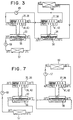
- coolant fluid is circulated to be cooled to 30°C by the radiator 60 and is further cooled to 20°C by the second stage evaporator 34, thereafter is provided to cool adsorbent S of the first first stage adsorption device 35 or the first second stage adsorption device 37 and rises in temperature from 20°C to 30°C, is provided to cool adsorbent S of the second first stage adsorption device 36 or the second second stage adsorption device 38 and rises in temperature from 30°C to 40°C, and is cooled by the radiator 60 to 30°C, as shown in FIG. 3, which shows solely a circulation system of coolant fluid.
- adsorbent S in the second stage adsorption devices 37 and 38 cooled to mean temperature of 35°C adsorbs refrigerant vapor of 20°C and so the adsorption rate of adsorbent S in the first stage adsorption devices 35 and 36 is approximately 21%, as shown by point P3 in FIG. 4, and the adsorption rate of adsorbent S in the second stage adsorption devices 37 and 38 is approximately 23%, as shown by point P3 in the same drawing.
- the refrigerant quantity adsorbed and desorbed by adsorbent S in the first stage adsorption devices 35 and 36 is approximately 15% and refrigerant quantity adsorbed and desorbed by adsorbent S in the second stage adsorption devices 37 and 38 is approximately 17%; thus, the refrigerant quantity adsorbed and desorbed is increased over the structure according to the prior art in FIG. 25. For this reason, refrigeration capacity can be heightened while avoiding large size of the adsorption devices 35 through 38.
- the second stage adsorption devices 37 and 38 may be cooled by coolant fluid cooled by the radiator 60
- the first stage adsorption devices 33 and 34 may be cooled by coolant fluid cooled by the second stage evaporator 34
- the cooler for air conditioning use 57 may be cooled by heat exchange refrigerant cooled by the first stage evaporator 33, as shown in FIG. 23.
- the radiator 60 and the second stage evaporator 34 are connected in series, and along with this, the heat exchanging passage 39 of the first first stage adsorption device 35 and the heat exchanging passage 41 of the first second stage adsorption device 37, as well as the heat exchanging passage 40 of the second first stage adsorption device 36 and the heat exchanging passage 42 of the second second stage adsorption device 38, are respectively connected in series, and so there are two systems of circulation paths to cause coolant fluid and heat exchange refrigerant to be circulated, piping structure for coolant fluid and heat exchange refrigerant is simplified, the two pumps 59 and 65 are sufficient, and manufacturing cost can be reduced.
- the adsorption devices adsorbing refrigerant vapor of lower evaporation temperature i.e., the heat exchanging passages 39 and 40 of the first stage adsorption devices 35 and 37
- the adsorption devices adsorbing refrigerant vapor of higher evaporation temperature i.e., the heat exchanging passages 41 and 42 of the second stage adsorption devices 36 and 38
- the adsorption devices adsorbing refrigerant vapor of higher evaporation temperature i.e., the heat exchanging passages 41 and 42 of the second stage adsorption devices 36 and 38
- a temperature differential between the temperature of the refrigerant vapor adsorbed by adsorbent S of the several stages of adsorption devices 35 through 38 and the temperature of the coolant fluid can be made to be mutually equivalent among the adsorption devices 35 through 38. Consequently, the differential between adsorption rate during adsorption by adsorbent S and adsorption rate during desorption by adsorbent S is equivalent in the several stages of adsorption devices 35 through 38, and it becomes possible for each of the several stages of adsorption devices 35 through 38 to supply a large quantity of refrigerant to the condenser 32.
- the evaporators 33 and 34 and the condenser 32 are discrete devices, and their structure is such that the first stage adsorption devices 35 and 36 and the second stage adsorption devices 37 and 38 adsorb refrigerant vapor evaporated by the evaporators 33 and 34 in the adsorption process and send desorbed refrigerant vapor to the condenser in the desorption process.
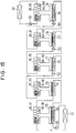
- FIG. 5 A structural example where this point is improved is shown in FIG. 5 as a second preferred embodiment of this invention. Briefly, the switching valves 43 through 50 to switch the passages of the refrigerant vapor are eliminated in the second embodiment shown in FIG. 5. Because of this, whereas an apparatus according to the above-described first embodiment disposes one first stage evaporator 33 to accommodate the first and second first stage adsorption devices 35 and 36 and one second stage evaporator 34 to accommodate the first and second second stage adsorption devices 37 and 38, an apparatus according to this second embodiment provides one evaporator 33, 33', 34, or 34' doubling in use as a condenser to accommodate respectively each of several adsorption devices 35 through 38.
- heating fluid flows successively to a heat exchanging passage 40 of the second first stage adsorption device 36 and a heat exchanging passage 42 of the second second stage adsorption device 38, thus heating adsorbent S of the second first stage and second stage adsorption devices 36 and 38, and refrigerant vapor desorbed from adsorbent S because of this flows into the evaporators 33' and 34'.
- coolant fluid cooled by the radiator 60 is flow divided by heat exchangers 56 and 56' provided respectively within the two second stage evaporators 34 and 34', and coolant fluid shunted to one heat exchanger 56' condenses refrigerant vapor of the evaporator 34' and thereafter flows into a heat exchanger 55' provided within one first stage evaporator 33', condenses refrigerant vapor of the evaporator 33', and returns to the radiator 60. Accordingly, refrigerant liquid condensed by the respective evaporators 33' and 34' is supplied respectively to the evaporators 33 and 34.
- Coolant fluid shunted to the other heat exchanger 56 is cooled by the evaporator 34, and thereafter flows successively to the heat exchanging passage 39 of the first first stage adsorption device 35 and the heat exchanging passage 41 of the first second stage adsorption device 37, thus cooling adsorbent S of the first first stage and second stage adsorption devices 35 and 37, and returns to the radiator 60. Because of this, adsorbent S of the respective adsorption devices 35 and 37 adsorbs refrigerant vapor evaporated by the respective evaporators 33 and 34. Accordingly, heat exchange fluid cooled by the heat exchanger 55 is supplied to a cooler 57, and chills air flowing within a vent duct of an air conditioner.
- refrigerant merely reciprocates among the several evaporators 33, 33', 34, and 34' corresponding to the respective adsorption devices 35 through 38, and so the switching valves 43 through 50 which must be of large size can be omitted.
- the number of three-way valves SV1 through SV6 and four-way valves FV1 and FV2 substituting for the omitted switching valves 43 through 50 is greater than in the first embodiment, but because fluid and not steam flows through these valves, they are advantageous spatially and in terms of cost, with no increase in pressure loss even when these valves are not structured to be of large size.
- FIG. 6 and FIG. 7 show a third embodiment of this invention. Firstly, characteristics of this third embodiment will be described briefly in comparison with the previously described first embodiment.
- the heat exchanging passages 39 and 41 or the heat exchanging passages 40 and 42 are connected in series when performing the adsorption process
- the heat exchanging passages 39 through 42 are independent passage systems.
- radiator 60 is independent, and is employed to generate coolant fluid supplied to the heat exchanging passages 41 and 42 of the second stage adsorption devices 35 and 37.
- the first stage evaporator 33 is employed solely for external area cooling
- the first stage and second stage evaporators 33 and 34 are, in addition to external area cooling use, employed to generate coolant fluid supplied to the heat exchanging passages 39 and 40 of the first stage adsorption devices 35 and 36.
- a heat exchanger 56 of the second stage evaporator 34, a heat exchanger 55 of the first stage evaporator 33, and a cooler for air conditioning use 57 are connected in series, and coolant fluid successively cooled by the heat exchangers 56 and 55 is sent in the direction of arrow C by a pump 66 provided between the heat exchanger 55 and the cooler for air conditioning use 57. Additionally, coolant fluid cooled by the radiator 60 is sent by a pump in the direction of arrow D.
- This embodiment is provided with four four-way valves 68 through 71 to switch a supply destination of coolant fluid and heating fluid. Accordingly, when these four-way valves 68 through 71 are in a state shown by solid lines in FIG. 6, coolant fluid successively cooled by the heat exchanger 56 of the second stage evaporator 34 and the heat exchanger 55 of the first stage evaporator 33 chills air blown inside a passenger compartment of the car by the cooler for air conditioning use 57, and thereafter passes successively through the heat exchanging passage 39 of the first first stage adsorption device 35 and the four-way valves 69 and 70 and is returned to the heat exchanger 56 of the second stage evaporator 34.
- Coolant fluid cooled by the radiator is sent by the pump 67 in the direction of arrow D passes successively through the four-way valve 71 and the heat exchanging passage 41 of the first second stage adsorption device 37, and is returned to the radiator 60.
- heating fluid discharged from the engine passes successively through a circulation path pipe 63, the four-way valve 68, the heat exchanging passage 40 of the second first stage adsorption device 36, the four-way valve 70, the heat exchanging passage 42 of the second second stage adsorption device 38, the four-way valve 71, and a return path pipe 64, and is returned to the engine.
- the first first stage and second stage adsorption devices 35 and 37 perform the adsorption process and the second first stage and second stage adsorption devices 36 and 38 perform the desorption process.
- coolant fluid cooled successively by the heat exchanger 56 of the second stage evaporator 34 and the heat exchanger 55 of the first stage evaporator 33 chills air blown within the passenger compartment of the car by the cooler for air conditioning use 57, and thereafter passes successively through the four-way valve 68, the heat exchanging passage 40 of the second first stage adsorption device 36, and the four-way valve 70, and is returned to the heat exchanger 56 of the second stage evaporator 34.
- Coolant fluid cooled by the radiator 60 is sent in the direction of arrow D by the pump 67, passes successively through the four-way valve 71, the heat exchanging passage 42 of the second second stage adsorption device 38, and the four-way valves 70 and 69, and is returned to the radiator 60.
- heating fluid discharged from the engine passes successively through the circulation path pipe 63, the four-way valve 68, the heat exchanging passage 39 of the first first stage adsorption device 35, the four-way valve 69, the heat exchanging passage 41 of the first second stage adsorption device 37, the four-way valve 71, and the return path pipe 64, and is returned to the engine.
- the second first stage and second stage adsorption devices 36 and 38 perform the adsorption process and the first first stage and second stage adsorption devices 35 and 37 perform the desorption process.
- FIG. 6 shows a state of opening or closure of the switching valves 43 through 50 when the first first stage and second stage adsorption devices 35 and 37 are in the adsorption process and the second first stage and second stage adsorption devices 36 and 38 are in the desorption process. Consequently, when the first first stage and second stage adsorption devices 35 and 37 are in the desorption process and the second first stage and second stage adsorption devices 36 and 38 are in the adsorption process, the switching valves 43 through 50 assume a state of opening or closure which is the opposite of that in FIG. 6.
- the first stage evaporator 33 in addition to functioning as a device for external area cooling, functions as a device for generating coolant fluid to be supplied to the heat exchanging passages 39 and 40 of the first first stage and second stage adsorption devices 35 and 36
- the second stage evaporator 33 in addition to functioning as a device for external area cooling, functions as a device for generating coolant fluid to be supplied to the heat exchanging passages 39 and 40 of the adsorption devices 35 and 36 of the first stage, which is the prior stage.
- FIG. 7 shows a passage system solely for coolant fluid, temperatures at various areas thereof, and evaporation temperatures of refrigerant liquid at the evaporators 33 and 34.
- the heat exchanging passages 39 and 41 and the heat exchange fluids 40 and 42 are mutually independent without being connected in series during supply of coolant fluid, but because the first stage evaporator 33, the second stage evaporator 34, and the cooler for air conditioning use 57 are connected in series, similarly to the first embodiment, two systems of circulation paths are sufficient for supplying coolant fluid, and so piping configuration is simplified, the two pumps 66 and 71 are also sufficient, and manufacturing cost can be reduced.
- FIG. 8 shows a fourth embodiment according to this invention.
- This fourth embodiment similarly to the previously described second embodiment and in contrast with the first embodiment, eliminates the switching valves 43 through 50 for switching passages of refrigerant vapor in the third embodiment. That is to say, whereas an apparatus according to the above-described third embodiment disposes one first stage evaporator 33 to accommodate the first and second first stage adsorption devices 35 and 36 and one second stage evaporator 34 to accommodate the first and second second stage adsorption devices 37 and 38, an apparatus according to this fourth embodiment provides one evaporator 33, 33', 34, or 34' doubling in use as a condenser to accommodate respectively each of several adsorption devices 35 through 38.
- heating fluid flows successively to a heat exchanging passage 40 of the second first stage adsorption device 36 and a heat exchanging passage 42 of the second second stage adsorption device 38, thus heating adsorbent S of the second first stage and second stage adsorption devices 36 and 38, and refrigerant vapor desorbed from adsorbent S because of this flows into the evaporators 33' and 34'.
- coolant fluid cooled by the radiator 60 is flow divided to a heat exchanging passage 41 of the first second stage adsorption device 37 and to a heat exchanger 56' provided within one second stage evaporator 34', and coolant fluid shunted to the heat exchanger 56' condenses refrigerant vapor of the evaporator 34', and thereafter flows into a heat exchanger 55' provided within the evaporator 33', condenses refrigerant vapor of the evaporator 33', and returns to the radiator 60. Accordingly, refrigerant liquid condensed by the respective evaporators 33' and 34' is supplied respectively to the evaporators 33 and 34.
- coolant fluid shunted to the heat exchanging passage 41 cools adsorbent S of the first second stage adsorption device 37 and returns to the radiator 60. Because of this, adsorbent S of the adsorption device 37 adsorbs refrigerant vapor evaporated in the evaporator 34.
- coolant fluid cooled successively by the heat exchangers 56 and 55 of the evaporators 34 and 33 supplied with refrigerant liquid from the evaporators 34' and 33' firstly is supplied to a cooler 57 to chill air flowing within a vent duct of an air conditioner, and thereafter passes through the heat exchanging passage 39 of the first first stage adsorption device 35 and is returned to the heat exchanging passage 56 of the evaporator 34. Accordingly, adsorbent S of the first first stage adsorption device 35 is cooled by coolant fluid flowing through the heat exchanging passage 39, and adsorbs refrigerant vapor evaporated by the evaporator 33.
- the switching valves 43 through 50 which must be of large size shown for the third embodiment can be omitted.
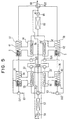
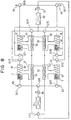
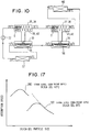
- FIG. 9 and FIG. 10 show a fifth embodiment of this invention.
- An apparatus according to this embodiment is devised so that a coolant fluid circulation path is made up of only one system.
- a pair of heat exchanging passages 39 and 41 of first first stage and second stage adsorption devices 35 and 37 and a pair of heat exchanging passages 40 and 42 of second first stage and second stage adsorption devices 36 and 38 are connected in series, and along with this, a radiator 60, a heat exchanger 56 of a second stage evaporator 34, a heat exchanger 55 of a first stage evaporator 33, and a cooler for air conditioning use 57 are connected in series, and a pump 72 to sent coolant fluid in the direction of arrow E is disposed on an outlet side of the cooler for air conditioning use 57.
- Two four-way valves 73 and 74 are provided to switch a supply destination of coolant fluid and heating fluid.
- coolant fluid successively cooled by the radiator 60, the heat exchanger 56 of the second stage evaporator 34, and the heat exchanger 55 of the first stage evaporator 33 chills air blown inside a passenger compartment of the car by the cooler for air conditioning use 57, and thereafter passes successively through the four-way valve 73, the heat exchanging passage 39 of the first first stage adsorption device 35, the heat exchanging passage 41 of the first second stage adsorption device 37, and the four-way valve 74, and is returned to the radiator 60.
- heating fluid discharged from the engine passes successively through a circulation path pipe 63, the four-way valve 73, the heat exchanging passage 40 of the second first stage adsorption device 36, the heat exchanging passage 42 of the second second stage adsorption device 38, the four-way valve 74, and a return path pipe 64, and is returned to the engine.
- the first first stage and second stage adsorption devices 35 and 37 perform the adsorption process and the second first stage and second stage adsorption devices 36 and 38 perform the desorption process.
- coolant fluid cooled successively by the radiator 60, the heat exchanger 56 of the second stage evaporator 34, and the heat exchanger 55 of the first stage evaporator 33 chills air blown within the passenger compartment of the car by the cooler for air conditioning use 57, and thereafter passes successively through the four-way valve 73, the heat exchanging passage 40 of the second first stage adsorption device 36, and the heat exchanging passage 42 of the second second stage adsorption device 38, and is returned to the radiator 60.
- heating fluid discharged from the engine passes successively through the circulation path pipe 63, the four-way valve 73, the heat exchanging passage 39 of the first first stage adsorption device 35, the heat exchanging passage 41 of the first second stage adsorption device 37, the four-way valve 74, and the return path pipe 64, and is returned to the engine.
- the second first stage and second stage adsorption devices 36 and 38 perform the adsorption process and the first first stage and second stage adsorption devices 35 and 37 perform the desorption process.
- FIG. 9 shows a state of opening or closure of switching valves 43 through 50 when the first first stage and second stage adsorption devices 35 and 37 are in the adsorption process and the second first stage and second stage adsorption devices 36 and 38 are in the desorption process. Consequently, when the first first stage and second stage adsorption devices 35 and 37 are in the desorption process and the second first stage and second stage adsorption devices 36 and 38 are in the adsorption process, the switching valves 43 through 50 assume a state of opening or closure which is the opposite of that in FIG. 9.
- coolant fluid cooled by the radiator 60 is further cooled by the second stage and first stage evaporators 34 and 33 and is supplied to the heat exchanging passages 39 and 41 or 40 and 42, and so refrigerant efficiency can be enhanced without leading to larger size, similarly to the first embodiment as was described above.
- FIG. 10 shows a circulation system for coolant fluid, temperatures at various areas thereof, and evaporation temperatures of refrigerant liquid at the evaporators 33 and 34.
- a circulation path of coolant fluid in particular has become a single system, and so coolant fluid piping configuration is further simplified, the one pump 72 suffices, and manufacturing cost can further be reduced.
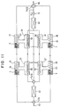
- FIG. 11 shows a sixth preferred embodiment according to this invention.
- This sixth embodiment similarly to the previously described second embodiment and in contrast with the first embodiment, eliminates the switching valves 43 through 50 for switching passages of refrigerant vapor in the fifth embodiment. That is to say, whereas an apparatus according to the above-described fifth embodiment disposes one first stage evaporator 33 to accommodate the first and second first stage adsorption devices 35 and 36 and one second stage evaporator 34 to accommodate the first and second second stage adsorption devices 37 and 38, an apparatus according to this sixth embodiment provides one evaporator 33, 33', 34, or 34' doubling in use as a condenser to accommodate respectively each of several adsorption devices 35 through 38.
- heating fluid flows successively to a heat exchanging passage 40 of the second first stage adsorption device 36 and a heat exchanging passage 42 of the second second stage adsorption device 38, thus heating adsorbent S of the second first stage and second stage adsorption devices 36 and 38, and refrigerant vapor desorbed from adsorbent S because of this flows into the evaporators 33' and 34'.
- coolant fluid cooled by the radiator 60 is flow divided by heat exchangers 56 and 56' provided respectively within the two second stage evaporators 34 and 34', and coolant fluid shunted to one heat exchanger 56' condenses refrigerant vapor of the evaporator 34', and thereafter flows into a heat exchanger 55' provided within the first stage evaporator 33', condenses refrigerant vapor of the evaporator 33', and returns to the radiator 60. Accordingly, refrigerant liquid condensed by the respective evaporators 33' and 34' is supplied respectively to the evaporators 33 and 34.
- Coolant fluid shunted to the other heat exchanger 56 is cooled by the evaporator 34, and thereafter further flows into the heat exchanger 55 of the evaporator 33 and is cooled by the evaporator 33. Thereafter, coolant fluid is supplied to the cooler 57, chills air flowing within a vent duct of an air conditioner, subsequently flows successively to the heat exchanging passage 39 of the first first stage adsorption device 35 and the heat exchanging passage 41 of the first second stage adsorption device 37, thus cooling adsorbent S of the first first stage and second stage adsorption devices 35 and 37, and returns to the radiator 60. Because of this, adsorbent S of the respective adsorption devices 35 and 37 adsorbs refrigerant vapor evaporated by the respective evaporators 33 and 34.
- the switching valves 43 through 50 shown according to the fifth embodiment which must be of large size can be omitted.
- FIG. 12 and FIG. 13 show a seventh preferred embodiment of this invention.
- An apparatus according to this embodiment is devised so that a coolant fluid circulation path is made up of only one system.
- This embodiment is provided with three or more stages, for example, five stages, of evaporators 75 through 79, and five stages of adsorption devices to correspond in a one-to-one relationship with the respective evaporators 75 through 79, and each stage of adsorption device is made up of two (i.e., a first and a second) adsorption devices 80 through 89.
- the several stages of evaporators 75 through 79 are mutually connected by capillary piping 54, so that refrigerant fluid supplied from a radiator 60 to the fifth stage evaporator 79 via capillary piping 53 is successively supplied to the prior stages of evaporators 78, 77, 76, and 75 via the capillary piping 54.
- the several stages of evaporators 75 through 79 are provided with heat exchangers 90 through 94.
- the first stage evaporator 75 is for external area cooling use, and the heat exchanger 90 thereof is connected in series with a cooler for air conditioning use 57.
- the second stage evaporator 76 through the fourth stage evaporator 78 are employed to generate coolant fluid to supply heat exchanging passages 95 through 100 of the respective adsorption devices 80 through 84 of the first stage through the third stage, which are the respective prior stages of the second stage evaporator 76 through the fourth stage evaporator 78.
- the remaining fifth stage evaporator 79 which is the final stage, cooperates with the radiator 60 and is used to generate coolant fluid to supply heat exchanging passages 101 through 104 of the respective fourth stage and fifth stage adsorption devices 86 through 89.
- the second first stage through fifth stage adsorption devices 81, 83, 85, 87, and 89 perform the desorption process.
- several three-way valves 105 through 118 and a four-way valve 119 are in a state shown by solid lines in FIG.
- coolant fluid cooled by the heat exchanger 91 of the second stage evaporator 76 circulates between the heat exchanging passage 95 of the first first stage adsorption device 80 and the heat exchanger 91
- coolant fluid cooled by the heat exchanger 92 of the third stage evaporator 77 circulates between the heat exchanging passage 97 of the first second stage adsorption device 82 and the heat exchanger 92
- coolant fluid cooled by the heat exchanger 93 of the fourth stage evaporator 78 circulates between the heat exchanging passage 99 of the first third stage adsorption device 84 and the heat exchanger 93
- coolant fluid cooled by the radiator 60 and the heat exchanger 94 of the fifth stage evaporator 79 circulates among the heat exchanging passage 101 of the first fourth stage adsorption device 86, the heat exchanging passage 103 of the first fifth stage adsorption device 88, the radiator 60, and the heat exchanger 94.
- heating fluid is supplied in series to the heat exchanging passages 96, 98, 100, 102, and 104 of the second first stage through fifth stage adsorption devices 81, 83, 85, 87, and 89.
- coolant fluid cooled by the heat exchanger 91 of the second stage evaporator 76 circulates between the heat exchanging passage 96 of the second first stage adsorption device 81 and the heat exchanger 91
- coolant fluid cooled by the heat exchanger 92 of the third stage evaporator 77 circulates between the heat exchanging passage 98 of the second second stage adsorption device 83 and the heat exchanger 92
- coolant fluid cooled by the heat exchanger 93 of the fourth stage evaporator 78 circulates between the heat exchanging passage 100 of the second third stage adsorption device 85 and the heat exchanger 93
- coolant fluid cooled by the radiator 60 and the heat exchanger 94 of the fifth stage evaporator 79 circulates between the heat exchanging passage 102 of the second fourth stage adsorption device 87, the heat exchanging passage 104 of the second fifth stage adsorption device 89, the radiator 60, and the heat exchanger 94.
- heating fluid is supplied in series to the heat exchanging passages 95, 97, 99, 101, and 103 of the first first stage through fifth stage adsorption devices 80, 82, 84, 86, and 88.
- Switching valves 121 through 140 to open and close inlets and outlets of the several adsorption devices 86 through 95 indicate, in FIG. 12, a state of opening and closure wherein the first first stage through fifth stage adsorption devices 80, 82, 84, 86, and 88 perform the adsorption process and the second first stage through fifth stage adsorption devices 81, 83, 85, 87, and 89 perform the desorption process.
- coolant fluid is cooled to 30°C by the radiator 60, and meanwhile a difference in evaporation temperature of refrigerant liquid between two sets of mutually adjacent evaporators is reduced in a case where evaporation temperature of refrigerant liquid of the first stage evaporator 75 is 10°C.
- refrigerant vapor vaporized at 10°C by the first stage evaporator 75 cools adsorbent S in the first stage adsorption devices 80 and 81 with coolant fluid cooled by the second stage evaporator 76 of a vaporization temperature which does not differ excessively from this 10°C.
- Such a relationship is similarly established also in the relationships of coolant fluid cooled by the second stage adsorption devices 82 and 83 and the third stage evaporator 77, coolant fluid cooled by the third stage adsorption devices 84 and 85 and the fourth stage evaporator 78, and coolant fluid cooled by the fourth stage and fifth stage adsorption devices 86 and 87, and 88 and 89, the radiator 60, and the fifth stage evaporator 79.
- the heat exchanging passages 101 and 102 of the fourth stage adsorption devices 86 and 87 and the heat exchanging passages 103 and 104 of the fifth stage adsorption devices 88 and 89 are connected in series, and so even as the adsorption devices have five stages, four systems of circulation paths are sufficient for coolant fluid thereof, and so piping configuration is simplified. Furthermore, pumps 141 through 145 to send coolant fluid also suffice with only five units, including one for the cooler for air conditioning use 57, and manufacturing cost can be held to a low level.
- the coolant fluid circulation path is shown in FIG. 13.
- FIG. 14 and FIG. 15 show an eighth preferred embodiment of this invention.
- An apparatus according to this embodiment is devised so that first stage and second stage evaporators 75 and 76 are used for external area cooling and for generating coolant fluid supplied to heat exchanging passages 95 and 96 of first stage adsorption devices 80 and 81, a fifth stage evaporator 79 is used for generating coolant fluid supplied to heat exchanging passages 101 and 102 of adsorption devices 86 and 87 of a fourth stage, which is the prior stage, and a radiator 60 is used for generating coolant fluid supplied to heat exchanging passages 103 and 104 of fifth stage adsorption devices 88 and 89.
- first first stage through fifth stage adsorption devices 80, 82, 84, 86, and 88 perform the adsorption process
- second first stage through fifth stage adsorption devices 81, 83, 85, 87, and 89 perform the desorption process
- four-way valves 146 and 160 and three-way valve 147 through 159 are in a state shown by solid lines, and coolant fluid successively cooled by heat exchangers 91 and 90 of the first stage and second stage evaporators 75 and 76 circulates among a cooler for air conditioning use 57, heat exchanging passages 95 and 97 of the first first stage and second stage adsorption devices 80 and 82, and the heat exchangers 91 and 90; coolant fluid cooled by a heat exchanger 92 of a third stage evaporator 77 is circulated between a heat exchanging passage 97 of the first second stage adsorption device 82 and the heat exchanger 92; coolant fluid cooled by a heat exchanger 93 of a fourth stage
- heating fluid is supplied in series to the heat exchanging passages 96, 98, 100, 102, and 104 of the second first stage through fifth stage adsorption devices 81, 83, 85, 87, and 89.
- coolant fluid cooled by the heat exchangers 91 and 90 of the second stage and first stage evaporators 76 and 75 circulates among the cooler for air conditioning use 57, the heat exchanging passages 96 and 98 of the second first stage and second stage adsorption devices 81 and 83, and the heat exchangers 91 and 91; coolant fluid cooled by the heat exchanger 92 of the third stage evaporator 77 is circulated between the heat exchanging passage 98 of the second second stage adsorption device 83 and the heat exchanger 92; coolant fluid cooled by the heat exchanger 93 of the fourth stage evaporator 78 is circulated between the heat exchanging passage 100 of the second third stage adsorption device 85 and the heat exchanger 93; coolant fluid cooled by the heat exchanger 94 of the fifth stage evaporator 79 is circulated between the heat exchanging passage 102 of the second fourth stage adsorption device 87 and the heat exchanger 94; and coolant fluid cooled by the radiator 60
- heating fluid is supplied in series to the heat exchanging passages 95, 97, 99, 101, and 103 of the second first stage through fifth stage adsorption devices 80, 82, 84, 86, and 88.
- circulation paths for coolant fluid are five systems even when structured in this way, and so pumps 161 through 165 also suffice with only five units, and effects similar to the above-described seventh embodiment can be obtained.
- FIG. 16 shows a ninth preferred embodiment of this invention.
- This apparatus disposes multiple stages of evaporators 166-1 through 166-n and adsorption devices 167-1 through 167-n, and connects in series a radiator 60, heat exchangers 168-1 through 168-n of the stages of evaporators 166-1 through 166-n, and a cooler for air conditioning use 57, and along with this, connects in series heat exchanging passages 169-1 through 169-n of the stages of adsorption devices 167-1 through 167-n.
- heating fluid is supplied in series to the heat exchanging passages 169-1 through 169-n of the several stages of adsorption devices 167-1 through 167-n.
- coolant fluid cooled by the radiator 60 is successively cooled by heat exchangers of evaporators on a prior stage side of the heat exchanger 168-n of the final stage evaporator 166-n, and firstly the cooler for air conditioning use 57 is cooled by coolant fluid discharged from the heat exchanger 168-1 of the first stage evaporator 166-1, and thereafter coolant fluid is recirculated to flow from the heat exchanging passage 169-1 of the first stage adsorption device 167-1 to the heat exchanging passage of the adsorption device of successively later stages, and be returned to the radiator 60.
- coolant fluid which has been cooled to 30°C by the radiator 60 is improved when cooled to 10°C by the time the heat exchanger 168-n of the first stage evaporator 166-1 is reached, and so it is sufficient if vaporization temperature of refrigerant liquid is slightly lower than 30°C at the final stage evaporator 166-n, and thereafter becomes lower a little at a time while moving to evaporators of progressively earlier stages, and so a temperature difference between refrigerant vapor adsorbed at the several stages of adsorption devices and adsorbent S is further reduced.
- cooling capacity can be further heightened by providing evaporators and adsorption devices in a multiplicity of stages.
- the circulation path for coolant fluid is solely one system, and so piping configuration for the circulation path for coolant fluid becomes simpler, and along with this, a single pump 170 is sufficient for sending coolant fluid, and reduction of manufacturing cost can be realized.
- FIG. 17 shows, in a case where silica gel has been used as adsorbent S, a relationship between particle size and adsorbing speed thereof for the first stage adsorption device and the second stage adsorption device.
- adsorbing speed of adsorbent S increases as refrigerant vapor pressure (temperature) grows higher, even at identical relative humidity.
- evaporation temperature (evaporation pressure) of refrigerant becomes increasingly higher at successively later stages.
- compactness of the adsorption device can be achieved by reducing the filled quantity of adsorbent S in the several stages of adsorption devices at increasingly later stages among the plurality of stages of adsorption devices, and moreover there is no danger of loss in adsorption capacity of refrigerant by adsorbent S even when such compactness is realized.
- adsorption speed of refrigerant vapor becomes faster, as shown in FIG. 17.
- the ability of the refrigerant vapor to penetrate within the adsorbent S layer becomes poorer as particle size grows smaller.
- Ideal particle size of adsorbent S is determined by superposition of these two conditions. At this time, as was described above, adsorbing speed of adsorbent S increases as evaporation pressure of the refrigerant increases, even at identical relative humidity, and so it is sufficient to cause particle size of adsorbent to become increasingly smaller in adsorption devices of successively later stages, where pressure of refrigerant vapor is high.
- an automotive air conditioner there may be cases where it is desirable to chill air blown within a vent duct by a cooler for air conditioning use 57 to around 0°C.
- a cooler for air conditioning use 57 to around 0°C.
- the evaporation temperature of refrigerant of the first stage evaporator 166-1 must be made to be approximately -5°C.
- the refrigerant freezes at such low temperatures. To avoid this, it is sufficient to use water to which a gelation point lowering agent has been compounded, but if the amount of added gelation point lowering agent is excessive, problems may occur such as a drop in refrigeration (cooling) capacity with an alcohol-base agent, or corrosion of the circulation path of the refrigerant with a saline agent.
- two adsorption devices connecting an evaporator doubling in use as a condenser are provided in a plurality of stages, such as in the structure shown for the second embodiment in FIG. 5, a structure is employed to independently seal refrigerant within each of the several stages, and among these several stages, water compounded with a gelation point lowering agent is employed as refrigerant in a required stage of a forward stage side, namely a stage whereat evaporation temperature of refrigerant becomes 0°C or less.
- refrigerant with a gelation point lowering agent intermixed therewithin is not at all stages but is restricted solely to necessary stages, and so a problem of a decline in refrigeration (cooling) capacity is avoided to the greatest extent possible, and along with this, a range in which there exists a chance of occurrence of corrosion or the like can be restricted to a small range.
- a required stage on a forward stage side employs an alcohol-based substance, for example ethanol, as refrigerant, and employs activated carbon as adsorbent S. Freezing of the refrigerant can reliably be prevented because the temperature at which the alcohol-based substance freezes is low, and because the activated carbon readily adsorbs the alcohol-based substance, a small quantity of adsorbent S can adsorb a large quantity of the alcohol-based substance, and compactness of the adsorption device can be realized.
- an alcohol-based substance for example ethanol
- activated carbon as adsorbent S
- coolant fluid flows from an adsorption device having an evaporation temperature on a low side to a heat exchanger of an adsorption device having a evaporation temperature on a high side, and so a heat exchange configuration of one type of opposing flow form is obtained.
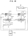
- a structure such as that of a tenth embodiment according to this invention as shown in FIG. 18 may be employed.
- the basic structure of the refrigeration apparatus according to this tenth embodiment is identical to the fifth embodiment shown in FIGS. 9 and 10.
- An inlet of a radiator 60 and an outlet of a cooler for air conditioning use 57 are connected to a mixing tank 170, and coolant fluid discharged from the radiator 60 and the cooler for air conditioning use 57 is intermixed in this mixing tank 170.
- Two outlets are provided on this mixing tank.
- One outlet is connected to a heat exchanger 56 of a second stage evaporator 34, which is the final stage evaporator, and the other outlet is connected to an intake port of a pump 72.
- coolant fluid discharged from the outlet of the radiator 60 and coolant fluid discharged from the outlet of the cooler for air conditioning use 57 are intermixed within the mixing tank 170 and coolant fluid subsequently to this mixing is supplied to the heat exchanger 56 of the second stage evaporator 34, and together with this, is supplied to a heat exchanging passage 39 of a first first stage adsorption device 35 or to a heat exchanging passage 40 of a second first stage adsorption device 36. Heat exchange efficiency is enhanced by doing this.
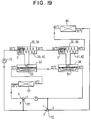
- FIG. 19 shows an eleventh preferred embodiment according to this invention.
- This apparatus intermixes coolant fluid discharged from an outlet of a radiator 60 and coolant fluid discharged from an outlet of a cooler for air conditioning use 57 without employing a mixing tank 170, and coolant fluid subsequent to this mixing is supplied to a heat exchanger 56 of a second stage evaporator 34, and along with this, is supplied to a heat exchanging passage 39 of a first first stage adsorption device 35 or a heat exchanging passage 40 of a second first stage adsorption device 36.
- two three-way valves 171 and 172 are provided as devices for adjusting the mixture ratio.
- the outlet of the cooler for air conditioning use 57 is connected to an inlet a of the three-way valve 171
- the outlet of the radiator 60 is connected to an inlet a of the three-way valve 172.
- one outlet b of the three-way valve 171 and one outlet b of the three-way valve 172 are integrated into a single unit and connected to an intake port of a pump 72, and along with this, another outlet c of the three-way valve 171 and another outlet c of the three-way valve 172 are integrated into a single unit and connected to the heat exchanger 56 of the second stage evaporator 34.
- a pump 173 is connected to the other outlet side of the three-way valve 171.
- the mixture ratio of coolant fluid from the radiator 60 and coolant fluid from the cooler for air conditioning use 57 is varied and the mixture can be supplied to the heat exchanger 56 or the heat exchanging passage 39 or 40 by regulating a degree of opening of the outlets b and c of the three-way valves 171 and 172.
- coolant fluid from the radiator 60 and coolant fluid from the cooler for air conditioning use 57 can be supplied at a mixture ratio of 50% each, similarly to the tenth embodiment depicted in FIG. 18.
- coolant fluid can flow in two respectively independent paths, being a path of the cooler for air conditioning use 57, the heat exchanger 56 of the second stage evaporator 34, and a heat exchanger 55 of a first stage evaporator 33, and a path of the heat exchanging passage 39 or 40 of the first stage adsorption device 35 or 36, a heat exchanging passage 41 or 42 or a second stage adsorption device 37 or 38, and the cooler for air conditioning use 57.
- FIG. 20 (a) shows a state wherein the first first stage and second stage adsorption devices 35 and 37 are in the adsorption process, and the second first stage and second stage adsorption devices 36 and 38 are in the desorption process.
- coolant fluid from the cooler for air conditioning use 57 is successively supplied to the heat exchanging passages 39 and 41 of the first first stage and second stage adsorption devices 35 and 37, and engine coolant water is successively supplied to the heat exchanging passages 40 and 42 of the second first stage and second stage adsorption devices 36 and 38.
- the four-way valve 73 alone is actuated and switched so that coolant fluid is supplied to the heat exchanging passage 40 of the second first stage adsorption device 36 and engine coolant water is supplied to the heat exchanging passage 39 of the first first stage adsorption device 35.
- coolant fluid remaining within the heat exchanging passages 39 and 41 of the first first stage and second stage adsorption devices 35 and 37 is expelled by engine coolant water and sent to the radiator 60, and together with this, engine coolant water remaining within the heat exchanging passages 40 and 42 of the second first stage and second stage adsorption devices 36 and 38 is expelled by coolant fluid and sent to the engine.
- the four-way valve 74 also is switched, and the first first stage and second stage adsorption devices 35 and 37 perform the desorption process, and along with this, the second first stage and second stage adsorption devices 36 and 38 perform the adsorption process.
- coolant fluid and engine coolant water remaining within the adsorption devices 35 through 38 ordinarily are sent respectively to the radiator 60 and to the engine by causing switching operation of the four-way valve 74 to be delayed after switching operation of the three-way valve 73.
- This feed time [correctly: "DELAY" -- SC] in the switching operation of the four-way valve 74 with respect to the switching operation of the three-way valve 73 shall be termed a "time lag.”
- coolant fluid immediately flows into the heat exchanging passage 40 of the second first stage adsorption device 36, but because the engine coolant water which was remaining within the heat exchanging passage 40 of the second first stage adsorption device 36 flows into the heat exchanging passage 42 of the second second stage adsorption device 38, the second second stage adsorption device 38 cannot shift to the adsorption process.
- engine coolant water immediately flows into the heat exchanging passage 39 of the first first stage adsorption device 35, but because the coolant fluid which was remaining within the heat exchanging passage 39 of the first first stage adsorption device 35 flows into the heat exchanging passage 41 of the first second stage adsorption device 37, the first second stage adsorption device 37 cannot shift to the desorption process. In this way, the second stage adsorption devices 37 and 38 enter a state wherein neither adsorption nor desorption can be executed during the time lag of the four-way valves 73 and 74, and cooling capacity is no longer exhibited.
- a twelfth embodiment of this invention shown in FIG. 21 exists to solve such problems.
- This embodiment differs from the fifth embodiment in disposing a four-way valve 174 as a passage switching device between heat exchanging passages 39 and 40 of first stage adsorption devices 35 and 36 on the one hand and heat exchanging passages 41 and 42 of second stage adsorption devices 37 and 38 on the other hand.
- outlets of the heat exchanging passages 39 and 40 of the first stage adsorption devices 35 and 36 and inlets of the heat exchanging passages 41 and 42 of the second stage adsorption devices 37 and 38 are respectively connected to one of the several ports of the four-way valve 174.
- a state wherein the heat exchanging passage 39 of the first first stage adsorption device 35 and the heat exchanging passage 41 of the first second stage adsorption device 37 are connected, and along with this, the heat exchanging passage 40 of the second first stage adsorption device 36 and the heat exchanging passage 42 of the second second stage adsorption device 38 are connected i.e., a first connected state
- a state wherein the heat exchanging passage 39 of the first first stage adsorption device 35 and the heat exchanging passage 42 of the second second stage adsorption device 38 are connected, and along with this, the heat exchanging passage 40 of the second first stage adsorption device 36 and the heat exchanging passage 41 of the second second stage adsorption device 37 are connected are switched due to switching operation of the four-way valve 174.
- FIG. 20 (a) shows a state wherein the first first stage and second stage adsorption devices 35 and 37 are in the adsorption process, and the second first stage and second stage adsorption devices 36 and 38 are in the desorption process.
- the four-way valve 174 is in the first switched state, coolant fluid from the cooler for air conditioning use 57 is successively supplied to the heat exchanging passages 39 and 41 of the first first stage and second stage adsorption devices 35 and 37, and engine coolant water is successively supplied to the heat exchanging passages 40 and 42 of the second first stage and second stage adsorption devices 36 and 38.
- the four-way valve 73 is actuated and switched so that coolant fluid is supplied to the heat exchanging passage 40 of the second first stage adsorption device 36 and engine coolant water is supplied to the heat exchanging passage 39 of the first first stage adsorption device 35.
- the four-way valve enters the second switched state.
- coolant fluid remaining within the heat exchanging passage 39 of the first first stage adsorption device 35 is expelled by engine coolant water and supplied to the heat exchanging passage 42 of the second second stage adsorption device 38, and together with this, engine coolant water remaining within the heat exchanging passage 40 of the second first stage adsorption device 36 is expelled by coolant fluid from the cooler for air conditioning use 57 and supplied to the heat exchanging passage 41 of the first second stage adsorption device 37.
- engine coolant water remaining within the heat exchanging passage 42 of the second second stage adsorption device 38 is expelled by coolant fluid from the heat exchanging passage 39 and returned to the engine, and along with this, coolant fluid remaining within the heat exchanging passage 41 of the first second stage adsorption device 37 is expelled by engine coolant water and sent to the radiator 60.
- the heat exchanging passages 39 through 42 of the several stages of adsorption devices 35 through 38 assume a state wherein heat exchanging passages of adsorption devices having the same execution process before and after switching are connected in series, and so coolant fluid and engine coolant water required to perform the process after switching can be received from heat exchanging passages of other adsorption devices.
- the four-way valve 174 is switched to the second switched state, and simultaneously thereto, the four-way valve 74 also is switched, and the first first stage and second stage adsorption devices 35 and 37 perform the desorption process, and along with this, the second first stage and second stage adsorption devices 36 and 38 perform the adsorption process.
- the heat exchanging passages 39 and 40 of the earlier stage adsorption devices 35 and 36 supply required fluid to the latter stage adsorption devices 37 and 38, and so time required to expel unnecessary fluid remaining in the heat exchanging passages 39 through 42 of the several adsorption devices 35 through 38 becomes equivalent to time to expel fluid remaining in the heat exchanging passage of one adsorption device, time lag is only about half that of the apparatus in FIG. 20, and processes can be switched within a short time.
- a thirteenth embodiment shown in FIG. 22 is an apparatus providing three stages of adsorption devices. By connecting heat exchanging passages of adsorption devices of such neighboring stages with a four-way valve FV, time lag can be shortened to the time required to expel fluid from the heat exchanging passage of the first stage adsorption device.
- the four-way valves 61, 62, 68 through 71, 73, and 74, the three-way valves 105 through 119, the four-way valves 146 and 160, and the three-way valves 147 through 159 correspond to passage switching devices for supplying coolant fluid and heating fluid alternately to the adsorption devices, but these are not exclusively limited to four-way or three-way valves and depending on piping configuration may be a combination of switching valves.
- the switching valves 43 through 50 and 121 through 140 correspond to refrigerant passage switching devices for causing pairs of adsorption devices of several stages to be selectively communicated with a condenser or evaporator, but these also may be three-way valves or four-way valves.
- the several stages of adsorption devices need not necessarily be provided in pairs, and may be a structure wherein a single adsorption device alternately executes adsorption and desorption.
- the first stage through fourth stage heat exchangers 90 through 93 may be structured to be connected in series to at least adjacent heat exchangers 90 and 91, 91 and 92, 92 and 93, 90 through 92, 91 through 93, or 90 through 93, supply coolant fluid in series to the cooler for air conditioning use 57 and the heat exchanger of the first stage adsorption device, supply coolant fluid in series to the heat exchanging passages of the first stage and Second stage adsorption devices, supply coolant fluid in series to the heat exchanging passages of the second stage and third stage adsorption devices, supply coolant fluid in series to the cooler for air conditioning use 57 and the heat exchanging passages of the first stage and second stage adsorption devices, or supply coolant fluid in series to the heat exchanging passages of the first stage through third stage adsorption devices.
- the fifth stage heat exchangers 91 through 94 may be structured to be connected in series to at least earlier stage heat exchangers 93, 93 and 92, or 93 through 91, allow coolant fluid to flow in series to the heat exchanging passages of the third stage through fifth stage adsorption devices, allow coolant fluid to flow in series to the heat exchanging passages of the second stage through fifth stage adsorption devices, or allow coolant fluid to flow in series to the heat exchanging passages of the first stage through fifth stage adsorption devices, and respectively return these to the radiator 60.
- a plurality of condensers 32 may be provided.
- the two evaporators 33 and 33' and 34 and 34' disposed in the several stages are mutually connected by capillary tubing so that refrigerant circulates, but the capillary tubing may be eliminated.
- the reason for this is because refrigerant liquid condensed by the evaporators 33, 33', 34, and 34' during desorption by the adsorption devices 35 through 38 may be collected as is in the respective evaporators, and refrigerant liquid collected within the evaporators 33, 33', 34, and 34' may evaporated during adsorption by the adsorption devices 35 through 38.
Landscapes
- Engineering & Computer Science (AREA)
- Physics & Mathematics (AREA)
- Mechanical Engineering (AREA)
- Thermal Sciences (AREA)
- General Engineering & Computer Science (AREA)
- Sorption Type Refrigeration Machines (AREA)
- Air-Conditioning For Vehicles (AREA)
Applications Claiming Priority (6)
| Application Number | Priority Date | Filing Date | Title |
|---|---|---|---|
| JP5772796 | 1996-03-14 | ||
| JP5772796 | 1996-03-14 | ||
| JP57727/96 | 1996-03-14 | ||
| JP29397496A JP3591164B2 (ja) | 1996-03-14 | 1996-11-06 | 吸着式冷凍装置 |
| JP293974/96 | 1996-11-06 | ||
| JP29397496 | 1996-11-06 |
Publications (3)
| Publication Number | Publication Date |
|---|---|
| EP0795725A2 true EP0795725A2 (de) | 1997-09-17 |
| EP0795725A3 EP0795725A3 (de) | 2002-10-02 |
| EP0795725B1 EP0795725B1 (de) | 2006-02-08 |
Family
ID=26398793
Family Applications (1)
| Application Number | Title | Priority Date | Filing Date |
|---|---|---|---|
| EP97104410A Expired - Lifetime EP0795725B1 (de) | 1996-03-14 | 1997-03-14 | Adsorptionskältegerät |
Country Status (4)
| Country | Link |
|---|---|
| US (1) | US5775126A (de) |
| EP (1) | EP0795725B1 (de) |
| JP (1) | JP3591164B2 (de) |
| DE (1) | DE69735216T2 (de) |
Cited By (5)
| Publication number | Priority date | Publication date | Assignee | Title |
|---|---|---|---|---|
| WO2007147280A3 (fr) * | 2006-06-23 | 2008-02-21 | Heig Vd | Dispositif generateur de froid a adsorption et clapet de retenue monte sur ce dispositif |
| WO2008138325A1 (de) * | 2007-05-11 | 2008-11-20 | Invensor Gmbh | Kältemaschine mit verschiedenen sorptionsmaterialien |
| DE10193103B3 (de) * | 2000-07-21 | 2017-06-22 | Denso Corporation | Kühlsystem für Wärmestrahler mit Betrieb eines Kühlsystems durch Wärmestrahler |
| EP3358274A3 (de) * | 2017-02-07 | 2018-09-12 | Panasonic Intellectual Property Management Co., Ltd. | Adsorptionskälteanlage, verfahren zur steuerung der adsorptionskälteanlage und kühlsystem |
| CN114537076A (zh) * | 2020-11-25 | 2022-05-27 | 冷王公司 | 环境控制系统中的热量利用 |
Families Citing this family (18)
| Publication number | Priority date | Publication date | Assignee | Title |
|---|---|---|---|---|
| SG82589A1 (en) * | 1998-12-10 | 2001-08-21 | Univ Singapore | A regenerative adsorption process and multi-reactor regenerative adsorption chiller |
| JP4192385B2 (ja) | 1999-12-17 | 2008-12-10 | 株式会社デンソー | 吸着式冷凍機 |
| US6477856B1 (en) * | 2001-07-24 | 2002-11-12 | Rocky Research | Recuperation in solid-vapor sorption system using sorption energy and vapor mass flow |
| GB0217607D0 (en) * | 2002-07-30 | 2002-09-11 | Oxford Instr Superconductivity | Refrigeration method and system |
| KR100535674B1 (ko) * | 2004-02-25 | 2005-12-09 | 엘지전자 주식회사 | 멀티 히트 펌프의 사방밸브 제어 방법 |
| JP3879762B2 (ja) * | 2005-03-29 | 2007-02-14 | ダイキン工業株式会社 | 調湿装置 |
| US20110048920A1 (en) * | 2009-08-28 | 2011-03-03 | Industrial Idea Partners, Inc. | Adsorbent - Adsorbate Desalination Unit and Method |
| US8597471B2 (en) | 2010-08-19 | 2013-12-03 | Industrial Idea Partners, Inc. | Heat driven concentrator with alternate condensers |
| US9273880B2 (en) * | 2013-08-14 | 2016-03-01 | Elwha Llc | Heating device with condensing counter-flow heat exchanger |
| CN104633982B (zh) * | 2013-11-13 | 2018-09-11 | 马勒国际公司 | 优选用于热驱动的吸附装置的蒸发单元以及吸附装置 |
| JP6028758B2 (ja) | 2014-03-24 | 2016-11-16 | 株式会社豊田中央研究所 | 吸着式ヒートポンプシステム及び冷熱生成方法 |
| US9789746B2 (en) * | 2014-03-25 | 2017-10-17 | Ford Global Technologies, Llc | Adsorption air-conditioning system |
| JP6065882B2 (ja) | 2014-06-30 | 2017-01-25 | 株式会社豊田中央研究所 | 吸着式ヒートポンプシステム及び冷熱生成方法 |
| JP6375286B2 (ja) * | 2015-12-25 | 2018-08-15 | 株式会社豊田中央研究所 | ヒートポンプ及び冷熱生成方法 |
| US9999867B2 (en) | 2016-06-29 | 2018-06-19 | Howard Y. Yuh | Composite adsorbent material |
| JP2019086171A (ja) * | 2017-11-01 | 2019-06-06 | 株式会社デンソー | 吸着式冷凍装置 |
| MX2020009304A (es) | 2018-03-07 | 2020-11-24 | Enersion Inc | Bomba de calor basada en adsorcion. |
| US12434194B2 (en) | 2023-02-03 | 2025-10-07 | King Fahd University Of Petroleum And Minerals | Vapor-absorption refrigeration system |
Citations (1)
| Publication number | Priority date | Publication date | Assignee | Title |
|---|---|---|---|---|
| JPH07120100A (ja) | 1993-04-27 | 1995-05-12 | Soc Natl Elf Aquitaine (Snea) | 固体吸収体を使用した冷却及び加熱装置 |
Family Cites Families (9)
| Publication number | Priority date | Publication date | Assignee | Title |
|---|---|---|---|---|
| US5598721A (en) * | 1989-03-08 | 1997-02-04 | Rocky Research | Heating and air conditioning systems incorporating solid-vapor sorption reactors capable of high reaction rates |
| US5419156A (en) * | 1990-06-04 | 1995-05-30 | Aerojet-General Corporation | Regenerative sorption compressor assembly |
| US5046319A (en) * | 1990-10-16 | 1991-09-10 | California Institute Of Technology | Regenerative adsorbent heat pump |
| JPH0542966A (ja) * | 1991-08-01 | 1993-02-23 | Maruka:Kk | 可食性皮膜を形成した加工食品包装材 |
| US5157938A (en) * | 1991-10-22 | 1992-10-27 | The United States Of America As Represented By The Administrator Of The National Aeronautics And Space Administration | Three-stage sorption type cryogenic refrigeration systems and methods employing heat regeneration |
| US5351493A (en) * | 1991-12-10 | 1994-10-04 | Sanyo Electric Co., Ltd. | Thermally driven refrigeration system utilizing metal hydrides |
| US5386705A (en) * | 1993-08-27 | 1995-02-07 | California Institute Of Technology | Staged regenerative sorption heat pump |
| US5463879A (en) * | 1994-01-04 | 1995-11-07 | California Institute Of Technology | Heat cascading regenerative sorption heat pump |
| JP3341516B2 (ja) * | 1994-09-19 | 2002-11-05 | 株式会社デンソー | 吸着式冷凍機 |
-
1996
- 1996-11-06 JP JP29397496A patent/JP3591164B2/ja not_active Expired - Lifetime
-
1997
- 1997-03-14 US US08/816,433 patent/US5775126A/en not_active Expired - Fee Related
- 1997-03-14 EP EP97104410A patent/EP0795725B1/de not_active Expired - Lifetime
- 1997-03-14 DE DE69735216T patent/DE69735216T2/de not_active Expired - Lifetime
Patent Citations (1)
| Publication number | Priority date | Publication date | Assignee | Title |
|---|---|---|---|---|
| JPH07120100A (ja) | 1993-04-27 | 1995-05-12 | Soc Natl Elf Aquitaine (Snea) | 固体吸収体を使用した冷却及び加熱装置 |
Cited By (5)
| Publication number | Priority date | Publication date | Assignee | Title |
|---|---|---|---|---|
| DE10193103B3 (de) * | 2000-07-21 | 2017-06-22 | Denso Corporation | Kühlsystem für Wärmestrahler mit Betrieb eines Kühlsystems durch Wärmestrahler |
| WO2007147280A3 (fr) * | 2006-06-23 | 2008-02-21 | Heig Vd | Dispositif generateur de froid a adsorption et clapet de retenue monte sur ce dispositif |
| WO2008138325A1 (de) * | 2007-05-11 | 2008-11-20 | Invensor Gmbh | Kältemaschine mit verschiedenen sorptionsmaterialien |
| EP3358274A3 (de) * | 2017-02-07 | 2018-09-12 | Panasonic Intellectual Property Management Co., Ltd. | Adsorptionskälteanlage, verfahren zur steuerung der adsorptionskälteanlage und kühlsystem |
| CN114537076A (zh) * | 2020-11-25 | 2022-05-27 | 冷王公司 | 环境控制系统中的热量利用 |
Also Published As
| Publication number | Publication date |
|---|---|
| US5775126A (en) | 1998-07-07 |
| DE69735216T2 (de) | 2006-11-02 |
| JP3591164B2 (ja) | 2004-11-17 |
| JPH09303900A (ja) | 1997-11-28 |
| EP0795725A3 (de) | 2002-10-02 |
| DE69735216D1 (de) | 2006-04-20 |
| EP0795725B1 (de) | 2006-02-08 |
Similar Documents
| Publication | Publication Date | Title |
|---|---|---|
| EP0795725B1 (de) | Adsorptionskältegerät | |
| JP4727051B2 (ja) | インタークーラ及びco2冷媒車両用空調装置 | |
| JP3341516B2 (ja) | 吸着式冷凍機 | |
| MXPA03001819A (es) | Sistema de compresion de vapor, reversible. | |
| JP2020147153A (ja) | 車載温調装置 | |
| JP2010001013A (ja) | 自動車用加熱、換気、および/または空調装置 | |
| CN107074069A (zh) | 热泵式车辆用空调系统 | |
| CN114475161A (zh) | 汽车的热管理系统及汽车 | |
| WO2021015270A1 (ja) | 熱管理装置 | |
| EP4688471A1 (de) | Vorrichtung zur temperierung eines raumes, gas-flüssigkeits-wärmetauscher und lastkraftwagen | |
| JP4718716B2 (ja) | ガスクーラ及び車載用空調装置 | |
| CN116442716A (zh) | 电动汽车热管理方法、系统和车辆 | |
| CN114604058A (zh) | 汽车的热管理系统及汽车 | |
| JPH0961001A (ja) | 吸着式冷却装置 | |
| CN116605005A (zh) | 一种车用热管理系统和汽车 | |
| JPH09196494A (ja) | 吸着式冷凍機 | |
| JP3353839B2 (ja) | 吸着式冷凍機の冷凍出力制御方法及び冷凍出力制御可能な吸着式冷凍機 | |
| JP4066485B2 (ja) | 冷凍装置 | |
| JPH1183234A (ja) | 複合熱移動装置 | |
| US5402653A (en) | Refrigerating apparatus provided with chemical type refrigerating unit and compression type heat pump | |
| JP4069691B2 (ja) | 車両用空調装置 | |
| CN114571952A (zh) | 汽车的热管理系统及汽车 | |
| JP2005326073A (ja) | 冷凍装置 | |
| JPH09196493A (ja) | 吸着式冷凍装置 | |
| JP3404947B2 (ja) | 熱交換器及び吸着式冷凍装置 |
Legal Events
| Date | Code | Title | Description |
|---|---|---|---|
| PUAI | Public reference made under article 153(3) epc to a published international application that has entered the european phase |
Free format text: ORIGINAL CODE: 0009012 |
|
| AK | Designated contracting states |
Kind code of ref document: A2 Designated state(s): DE FR GB IT |
|
| PUAL | Search report despatched |
Free format text: ORIGINAL CODE: 0009013 |
|
| AK | Designated contracting states |
Kind code of ref document: A3 Designated state(s): DE FR GB IT |
|
| 17P | Request for examination filed |
Effective date: 20020909 |
|
| GRAP | Despatch of communication of intention to grant a patent |
Free format text: ORIGINAL CODE: EPIDOSNIGR1 |
|
| GRAS | Grant fee paid |
Free format text: ORIGINAL CODE: EPIDOSNIGR3 |
|
| GRAA | (expected) grant |
Free format text: ORIGINAL CODE: 0009210 |
|
| AK | Designated contracting states |
Kind code of ref document: B1 Designated state(s): DE FR GB IT |
|
| REG | Reference to a national code |
Ref country code: GB Ref legal event code: FG4D |
|
| REF | Corresponds to: |
Ref document number: 69735216 Country of ref document: DE Date of ref document: 20060420 Kind code of ref document: P |
|
| ET | Fr: translation filed | ||
| PLBE | No opposition filed within time limit |
Free format text: ORIGINAL CODE: 0009261 |
|
| STAA | Information on the status of an ep patent application or granted ep patent |
Free format text: STATUS: NO OPPOSITION FILED WITHIN TIME LIMIT |
|
| 26N | No opposition filed |
Effective date: 20061109 |
|
| PGFP | Annual fee paid to national office [announced via postgrant information from national office to epo] |
Ref country code: GB Payment date: 20090311 Year of fee payment: 13 |
|
| PGFP | Annual fee paid to national office [announced via postgrant information from national office to epo] |
Ref country code: IT Payment date: 20090319 Year of fee payment: 13 |
|
| PGFP | Annual fee paid to national office [announced via postgrant information from national office to epo] |
Ref country code: FR Payment date: 20090316 Year of fee payment: 13 |
|
| GBPC | Gb: european patent ceased through non-payment of renewal fee |
Effective date: 20100314 |
|
| REG | Reference to a national code |
Ref country code: FR Ref legal event code: ST Effective date: 20101130 |
|
| PG25 | Lapsed in a contracting state [announced via postgrant information from national office to epo] |
Ref country code: FR Free format text: LAPSE BECAUSE OF NON-PAYMENT OF DUE FEES Effective date: 20100331 |
|
| PG25 | Lapsed in a contracting state [announced via postgrant information from national office to epo] |
Ref country code: IT Free format text: LAPSE BECAUSE OF NON-PAYMENT OF DUE FEES Effective date: 20100314 Ref country code: GB Free format text: LAPSE BECAUSE OF NON-PAYMENT OF DUE FEES Effective date: 20100314 |
|
| PGFP | Annual fee paid to national office [announced via postgrant information from national office to epo] |
Ref country code: DE Payment date: 20120411 Year of fee payment: 16 |
|
| REG | Reference to a national code |
Ref country code: DE Ref legal event code: R119 Ref document number: 69735216 Country of ref document: DE Effective date: 20131001 |
|
| PG25 | Lapsed in a contracting state [announced via postgrant information from national office to epo] |
Ref country code: DE Free format text: LAPSE BECAUSE OF NON-PAYMENT OF DUE FEES Effective date: 20131001 |