EP0795755A2 - Nichtharmonische Wellenformanalyse für Synthese, Interpolation und Extrapolation - Google Patents
Nichtharmonische Wellenformanalyse für Synthese, Interpolation und Extrapolation Download PDFInfo
- Publication number
- EP0795755A2 EP0795755A2 EP97103656A EP97103656A EP0795755A2 EP 0795755 A2 EP0795755 A2 EP 0795755A2 EP 97103656 A EP97103656 A EP 97103656A EP 97103656 A EP97103656 A EP 97103656A EP 0795755 A2 EP0795755 A2 EP 0795755A2
- Authority
- EP
- European Patent Office
- Prior art keywords
- waveform
- summation
- analysis
- period
- interval
- Prior art date
- Legal status (The legal status is an assumption and is not a legal conclusion. Google has not performed a legal analysis and makes no representation as to the accuracy of the status listed.)
- Withdrawn
Links
Images






Classifications
-
- G—PHYSICS
- G10—MUSICAL INSTRUMENTS; ACOUSTICS
- G10L—SPEECH ANALYSIS TECHNIQUES OR SPEECH SYNTHESIS; SPEECH RECOGNITION; SPEECH OR VOICE PROCESSING TECHNIQUES; SPEECH OR AUDIO CODING OR DECODING
- G10L25/00—Speech or voice analysis techniques not restricted to a single one of groups G10L15/00 - G10L21/00
- G10L25/48—Speech or voice analysis techniques not restricted to a single one of groups G10L15/00 - G10L21/00 specially adapted for particular use
-
- G—PHYSICS
- G01—MEASURING; TESTING
- G01H—MEASUREMENT OF MECHANICAL VIBRATIONS OR ULTRASONIC, SONIC OR INFRASONIC WAVES
- G01H3/00—Measuring characteristics of vibrations by using a detector in a fluid
- G01H3/04—Frequency
- G01H3/08—Analysing frequencies present in complex vibrations, e.g. comparing harmonics present
-
- G—PHYSICS
- G01—MEASURING; TESTING
- G01R—MEASURING ELECTRIC VARIABLES; MEASURING MAGNETIC VARIABLES
- G01R23/00—Arrangements for measuring frequencies; Arrangements for analysing frequency spectra
- G01R23/16—Spectrum analysis; Fourier analysis
-
- G—PHYSICS
- G06—COMPUTING OR CALCULATING; COUNTING
- G06F—ELECTRIC DIGITAL DATA PROCESSING
- G06F17/00—Digital computing or data processing equipment or methods, specially adapted for specific functions
- G06F17/10—Complex mathematical operations
- G06F17/17—Function evaluation by approximation methods, e.g. inter- or extrapolation, smoothing, least mean square method
Definitions
- This invention relates to a method for waveform analysis, and more particularly, to an improved method for non-harmonic analysis of waveforms in which intervals and/or frequencies (or periods) for analysis can be selected in an arbitrary manner. More particularly, the invention concerns such method which finds utility in a wide variety of applications that require waveform processing, such as interpolation of a waveform with missing portions, restoration of a clipped (or saturated) waveform prediction, processing of image and sound signals, determination of the pitch period of a harmonic waveform and the like.
- Prony's method provides for detection of sinusoids which actually constitute a waveform to be analyzed and, in principles, permits a restoration and prediction of the waveform through waveform synthesis.
- the method has not been put into practical use because the number of sinusoids constituting the waveform must be known and also because the method is susceptible to influences by noises.
- the invention is generally directed to a method for making a non-harmonic frequency analysis of a discrete waveform as defined in the appended claims.
- This method comprises: multiplying an arbitrary interval of a discrete waveform to be analyzed by a sine function having an arbitrary period to provide a first product value; summing said first product value over said arbitrary interval to provide a first summation value; multiplying said arbitrary interval of the discrete waveform by a cosine function having said arbitrary period to provide a second product value; summing said second product value over said arbitrary interval to provide a second summation value; multiplying said sine function and said cosine function to provide a third product value; summing said third product value over said arbitrary interval to provide a third summation value; squaring said sine function to provide a fourth square value; summing said fourth square value over said arbitrary interval to provide a fourth summation value, squaring said cosine function to provide a fifth square value; summing said fifth square value over
- a (T) R (sin (2 ⁇ m/T)) 2
- R (m;T) W (m) - X (T) sin (2 ⁇ m/T) - Y (T) cos (2 ⁇ m/T)
- W (m) K 1 sin (2 ⁇ m/T 1 + ⁇ 1 )
- the residual quantity is equal to zero.
- W (m) K 1 sin (2 ⁇ m/T 1 + ⁇ 1 ) + K 2 sin (2 ⁇ m/T 2 + ⁇ 2 ) + K 3 sin (2 ⁇ m/T 3 + ⁇ 3 ) + ...
- d 1 and d 2 are quantities which vary with m but have an averarge equal to zero.
- a first residual waveform R (m; T 1 ) is derived by substracting a first sinusoid, S (m, T 1 ), as expressed by the right side of Equation 15 from W (m).
- a second sinusoid, S (m, T 2 ) is derived from R (m; T 1 ) is derived from W (m), and a second residual waveform, R (m; T 1 , T 2 ) is derived by subtracting the second sinusoid S (m, T 2 ) from R (m; T 1 ).
- the present invention will be described in detail in the context of interpolating a discontinuous waveform and then of restoring a clipped waveform.
- a waveform as depicted at (a) is discontinuous in that it lacks data from b to c; and d to e. Also, a waveform as shown at (b) has its positive and negative peaks clipped from b to c and d to e, respectively.
- the original waveform W (m) which includes segments as indicated by broken lines, can be represented by synthesizing the above-mentioned first to n-th sinusoids. If the W (m) is an almost periodic function which can be represented by synthesis of a definite number of sinusoids, the difference between W (m) and the synthesized waveform is:
- W(m) - k 1 N S (m, T k )
- the maximum period and the minimum frequency for analysis are M and 1/M, respectively, where M is the length of an interval of the wave data to be analyzed. It should be noted, however, that there are no such limitations on the non-harmonic frequency analysis according to the present invention, as shown by way of examples of calculations given below:
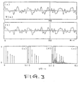
- the waveform W (m) as shown is comprised of five sinusoids.
- the result is the waveform as shown in Fig. 3(b).
- FIG. 4(a) there is shown the waveform W (m) of Fig. 3(a) added with white noise.
- Figures 4(c), (d) and (e) are spectrograms similar to Fig. 3(c), (d) and (e), respectively, and show that the present non-harmonic waveform analysis is significantly superior to the conventional FFT in removing adverse effects of noises.
- the period T was given as an integer equal to 2 to 128.
- the five sinusoids were derived with their periods equal to 121; 67; 37; 29; and 23.
- the periods of the five sinusoids which comprise the waveform W (m) of Fig. 3(a) and 4(a) are 120; 67; 37; 29; and 23.
- the period at which the residual quantity is a local minimum can be determined in the following manner:
- a plurality of bands each comprised of a set of k periods are defined, starting with a first band comprised of periods u 1 to u k , a second band comprised of periods u k+1 to u 2k ,..., and the like.
- the period at which E (T) in Equation 10 is a local minimum is determined. If the period where the minimum obtained is located adjacent an end of the band, the band is combined with its adjacent band and the period at which E (T) is a minimum is determined for the two adjacent bands.
- FIG. 5 there is shown a block diagram of an embodiment which utilizes the present non-harmonic waveform analysis to remove steady-state noise from an audio signal.
- reference numeral 1 designates a waveform analysis block where each segment of an audio waveform is subjected to the present non-harmonic waveform analysis to obtain parameters which are determinative of sinusoids as detected.
- the audio waveform is divided into segments of approximately 20 ms in length prior to undergoing the non-harmonic analysis.
- the sinusoid removal block 3 operates in response to the output of the frequency memory block 2 by removing only those sinusoids occurring in one immediately previous segment.
- the remaining sinusoids, which pass through the sinusoid removed block 3, are fed to a waveform output of the input waveform.
- a microphone M sends a speech signal to an analog-to-digital converter A 1 and the resulting converter output is divided into segments of a predetermined length, e.g., 20 ms for application to a waveform analysis block 1 a .
- each segment is subjected to the present non-harmonic waveform analysis to derive certain parameters of sinusoids contained in each segment, such as the amplitude of sine functions, the amplitude of cosine functions, the period of frequency.
- the telephone system includes a transmitter/receiver W connected to an antenna.
- the receiver portion of W receives a transmitted speech signal via the antenna and applies the signal as received to another analog-to-digital converter A 2 as well as to a power amplifier P.
- the power amplifier is connected to a loudspeaker S.
- the digital output of the analog-to-digital converter A 2 is divided into segments of the predetermined length, e.g., 20 ms, and each segment is applied to another waveform analysis block 1 b to subject it to the present non-harmonic waveform analysis.
- the parameters of sinusoids contained in each waveform segment, as derived by the analysis, include the frequency or period.
- the parameter outputs from the waveform analysis blocks 1 a and 1 b are applied to a waveform removal block 3. If any sinusoids from 1 a have the same frequencies as those from 1 b , the waveform removal block 3 operates to block passage of parameters associate with such frequency-matched sinusoids from the wave form analysis block 1 a to a waveform synthesis block 4. Based on the remaining parameters received from the waveform removal block 3, the waveform synthesis block 4 functions to synthesize the waveform of the speech signal from the microphone M. By so doing, sounds emitted from the loudspeaker S into the microphone M due to coupling therebetween are removed thus preventing occurrence of howling or echoes.
- the present non-harmonic waveform analysis is particularly suited for use in the hands-free telephone system for automotive use because it is not susceptible to varying transmission characteristics between the loudspeaker and the microphone and also because extraneous noise and double-talk do not cause any malfunctioning.
- the waveform analysis blocks 1 a and 1 b , the waveform removal block 3 and the waveform synthesis block 4 were implemented by a digital signal processor DSP56301 commercially available from Motorolla, Inc.
- DSP56301 digital signal processor
- the interval for analysis used was 32 ms.
- Each frame or interval of the audio waveform was converted into 256 data samples which were subjected to the present non-harmonic analysis using 256 frequencies. Forty sinusoids were detected and the time required for processing was approximately 20 ms.
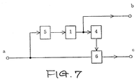
- FIG. 7 there is illustrated a block diagram of a further embodiment which utilizes the present non-harmonic waveform analysis for purposes of signal bandwidth compression.
- an audio signal or an image signal has higher power for lower frequency components. Accordingly, if such lower frequency components can be converted into parameters determinative of sinusoids which comprise the components, transmitting or recording such parameters in place of the lower frequency components per se would result in a significant reduction in signal bandwidth.
- the present non-harmonic waveform analysis is particularly suitable for analysis of the image signal because it contains low frequency components whose periods are longer than the length of the wave data W (m) as mentioned above.
- this down sampling requires a lowpass filter to remove noise due to aliasing. Since the use of such a lowpass filter requires the wave data W (m) to be sufficiently longer than a desired cutoff period, however, the down sampling is not compatible with the analysis of the image signal.
- the present non-harmonic waveform analysis does not suffer from the above-said disadvantage resulting from using the lowpass filter, since it can utilize "random sampling (down sampling at random intervals)" to suppress aliasing noise without use of the lowpass filter.
- the wave data W (m) appearing at an input terminal a is supplied to a sampling block 5 where it is subjected to random down sampling prior to undergoing the present non-harmonic waveform analysis.
- the output of the sampling block 5 is fed to a waveform analysis block 1 which in turn subjects digital samples resulting from the random sampling to the present non-harmonic waveform analysis.
- the resulting parameters, such as X (T k ), Y (T k ) and T k of sinusoids as detected are fed to parameter output terminal b as well as to a waveform synthesis block 4.
- the parameter input from the waveform analysis block 1 is used to derive sinusoids and accordingly waveforms of lower frequency components through synthesis.
- the synthesized waveforms are then supplied to a waveform subtraction block 6 which also receives the wave data W (m) from the input terminal a.
- the waveform subtraction block 6 operates to subtract the synthesized waveforms from the input wave data W (m), resulting in a residual waveform R (m) to be fed to an output terminal c.
- a combination of the parameter values at the parameter output terminal b and the residual waveform R (m) at the output terminal c enables a complete restoration of the original wave data. Accordingly, it should be noted that the present non-harmonic waveform analysis has the significant advantage of reducing the necessary bandwidth (or bit number) to transmit or record wave data.
- the power of the R k (m) can be made sufficiently smaller than the power of W k (m).
- the parameters of each sinusoid can be expressed as X (T j ), Y (T j ), and T j . Accordingly, it is possible to effect bandwidth compression by transmitting R k (m) and N sets of parameters instead of W k (m).
- the lower frequency components of the wave data of the (k + 1)th to (k + g)th lines can be replaced with the wave data of the k-th line and the N sets of parameters. Accordingly, the transmission of the N sets of parameters and the residual waveform R k (m) of each line results in a further bandwidth compression.
- the application of the above-described signal processing to wave data of the same lines of different frames will provide for a much greater bandwidth compression.
- FIG. 8 there is shown a flow chart of a waveform analysis routine which utilizes the fast Fourier transform (FFT) for preprocessing to reduce the time required for analysis.
- the routine inputs a discrete waveform W (m) a 11.
- the next step 13 is the waveform preprocessing by FFT where the input waveform data R k (m) is subjected to FFT to derive a set of power spectra V (n/M) of different magnitudes, from which the power spectrum V (r/M) of the maximum magnitude is determined.
- FFT fast Fourier transform
- the routine applies the present non-harmonic waveform analysis to the results of the FFT preprocessing to narrow down the period T k+1 at which the residual quantity E (T) is a local minimum. This is accomplished by performing calculations on Equations 1 to 7 for periods in the neighbourhood of M/r, or for M/(r + 1/2) ⁇ T ⁇ M/(r-1/2) , by varying the period T with a small step.
- the amplitude X (T k+1 ) of a sine function and the amplitude Y (T k+1 ) of a cosine function are obtained.
- a k+1 X (T k+1 ) ;
- B k+1 Y (T k+1 ) .
- these data, T k+1 , A k+1 , and B k+1 , are stored as the specific parameters determinative of the (k + 1)th sinusoid.
- the waveform data R k+1 (m) is derived by subtracting the (k + 1)th sinusoid, S (m, T k+1 ), from the waveform data R k (m).
- the waveform data R k+1 (m) is subjected to the same analyses as described above to detect a (k + 2)th sinusoid. This analysis will be repeated a predetermined number of times or until the residual quantity reaches a predetermined value.
- a personal computer manufactured by Micron, Inc. under the model name MILLENIA was used.
- a wave data under test was converted into 512 digital samples and the resolution for analysis was equivalent to 1/256 octave-band. Approximately 2.4 seconds were needed to detect sixteen frequencies.
- the next step 14 is the present non-harmonic waveform analysis which is performed to derive the amplitude X (T) of a sine function and the amplitude Y (T) of a cosine function.
- a residual waveform, R N (m, T 1 ) is derived by removing up to an N-th harmonic waveforms having a fundamental period T 1 .
- j is incremented from 1 to 2
- a residual waveform R N (m,T 2 ) is derived by subtracting up to an N-th harmonic waveforms having a fundamental period T 2 from R 0 (m) by following the same steps 24 to 25 sequentially.
- the power of the sinusoid becomes a local maximum at the particular period where the power of the residual waveform is a minimum. Accordingly, if T ⁇ M, the period at which the residual quantity becomes a minimum can be approximated to the period at which the sum of squared X (T) and squared Y (T) is a maximum.
Landscapes
- Physics & Mathematics (AREA)
- Engineering & Computer Science (AREA)
- General Physics & Mathematics (AREA)
- Mathematical Physics (AREA)
- Computational Mathematics (AREA)
- Mathematical Analysis (AREA)
- Mathematical Optimization (AREA)
- Pure & Applied Mathematics (AREA)
- Theoretical Computer Science (AREA)
- Data Mining & Analysis (AREA)
- General Engineering & Computer Science (AREA)
- Audiology, Speech & Language Pathology (AREA)
- Databases & Information Systems (AREA)
- Algebra (AREA)
- Computational Linguistics (AREA)
- Signal Processing (AREA)
- Health & Medical Sciences (AREA)
- Software Systems (AREA)
- Human Computer Interaction (AREA)
- Acoustics & Sound (AREA)
- Multimedia (AREA)
- Compression, Expansion, Code Conversion, And Decoders (AREA)
- Complex Calculations (AREA)
- Measurement Of Mechanical Vibrations Or Ultrasonic Waves (AREA)
Applications Claiming Priority (2)
| Application Number | Priority Date | Filing Date | Title |
|---|---|---|---|
| JP8085621A JPH09243679A (ja) | 1996-03-05 | 1996-03-05 | 任意区間波形を用いた非調和的周波数分析法 |
| JP85621/96 | 1996-03-05 |
Publications (2)
| Publication Number | Publication Date |
|---|---|
| EP0795755A2 true EP0795755A2 (de) | 1997-09-17 |
| EP0795755A3 EP0795755A3 (de) | 1998-05-20 |
Family
ID=13863925
Family Applications (1)
| Application Number | Title | Priority Date | Filing Date |
|---|---|---|---|
| EP97103656A Withdrawn EP0795755A3 (de) | 1996-03-05 | 1997-03-05 | Nichtharmonische Wellenformanalyse für Synthese, Interpolation und Extrapolation |
Country Status (3)
| Country | Link |
|---|---|
| US (1) | US6629049B2 (de) |
| EP (1) | EP0795755A3 (de) |
| JP (1) | JPH09243679A (de) |
Cited By (6)
| Publication number | Priority date | Publication date | Assignee | Title |
|---|---|---|---|---|
| WO1999018520A1 (en) * | 1997-10-07 | 1999-04-15 | Massachusetts Institute Of Technology | Nonuniform sampling for spectral and related applications |
| DE19751218A1 (de) * | 1997-11-19 | 1999-05-20 | Schenck Vibro Gmbh | Verfahren und Vorrichtung zur Meßsignalauswertung |
| WO2003003030A1 (en) * | 2001-06-29 | 2003-01-09 | Teradyne, Inc. | Low leakage technique for determining power spectra of non-coherently sampled data |
| EP1200925A4 (de) * | 1998-11-30 | 2005-05-11 | Elster Electricity Llc | System und verfahren zur frequenzkompensation in einem energiemesser |
| CN103226039A (zh) * | 2013-04-08 | 2013-07-31 | 哈尔滨工程大学 | 一种电液伺服振动台正弦振动试验谐波辨识方法 |
| WO2014153606A1 (en) * | 2013-03-26 | 2014-10-02 | Barratt Lachlan Paul | Audio filtering with virtual sample rate increases |
Families Citing this family (5)
| Publication number | Priority date | Publication date | Assignee | Title |
|---|---|---|---|---|
| JP3802293B2 (ja) * | 1999-10-21 | 2006-07-26 | ヤマハ株式会社 | 楽音処理装置および楽音処理方法 |
| JP4318119B2 (ja) * | 2004-06-18 | 2009-08-19 | 国立大学法人京都大学 | 音響信号処理方法、音響信号処理装置、音響信号処理システム及びコンピュータプログラム |
| US7643921B2 (en) * | 2004-09-03 | 2010-01-05 | Continental Automotive Systems Us, Inc. | Clipped sensor data estimator |
| KR100767188B1 (ko) * | 2007-03-28 | 2007-10-15 | 정두호 | 맞춤형 인테리어 자재 공급 방법 |
| JP6181892B1 (ja) * | 2017-03-14 | 2017-08-16 | アルインコ株式会社 | 無線通信装置及び無線通信システム |
Family Cites Families (7)
| Publication number | Priority date | Publication date | Assignee | Title |
|---|---|---|---|---|
| US3824384A (en) * | 1971-04-19 | 1974-07-16 | Hitachi Ltd | Frequency analyzer for analyzing a time function of a quantity |
| US4334273A (en) * | 1979-04-24 | 1982-06-08 | Kokusai Denshin Denwa Co., Ltd. | Signal processing system using a digital technique |
| SE430554B (sv) * | 1982-04-06 | 1983-11-21 | Ericsson Telefon Ab L M | Anordning for att identifiera digitala flerfrekvenssignaler |
| US4499550A (en) * | 1982-09-30 | 1985-02-12 | General Electric Company | Walsh function mixer and tone detector |
| JPH05197742A (ja) * | 1992-01-21 | 1993-08-06 | Takayoshi Hirata | 複合正弦波形を用いた波形データの予測法 |
| WO1994018573A1 (en) | 1993-02-02 | 1994-08-18 | Yoshimutsu Hirata | Non-harmonic analysis of waveform data and synthesizing processing system |
| US5684920A (en) * | 1994-03-17 | 1997-11-04 | Nippon Telegraph And Telephone | Acoustic signal transform coding method and decoding method having a high efficiency envelope flattening method therein |
-
1996
- 1996-03-05 JP JP8085621A patent/JPH09243679A/ja active Pending
-
1997
- 1997-03-03 US US08/810,195 patent/US6629049B2/en not_active Expired - Fee Related
- 1997-03-05 EP EP97103656A patent/EP0795755A3/de not_active Withdrawn
Cited By (14)
| Publication number | Priority date | Publication date | Assignee | Title |
|---|---|---|---|---|
| WO1999018520A1 (en) * | 1997-10-07 | 1999-04-15 | Massachusetts Institute Of Technology | Nonuniform sampling for spectral and related applications |
| US6005664A (en) * | 1997-10-07 | 1999-12-21 | Massachusetts Institute Of Technology | Nonuniform sampling for spectral and related applications |
| DE19751218A1 (de) * | 1997-11-19 | 1999-05-20 | Schenck Vibro Gmbh | Verfahren und Vorrichtung zur Meßsignalauswertung |
| EP1200925A4 (de) * | 1998-11-30 | 2005-05-11 | Elster Electricity Llc | System und verfahren zur frequenzkompensation in einem energiemesser |
| WO2003003030A1 (en) * | 2001-06-29 | 2003-01-09 | Teradyne, Inc. | Low leakage technique for determining power spectra of non-coherently sampled data |
| US6687630B2 (en) | 2001-06-29 | 2004-02-03 | Teradyne, Inc. | Low leakage technique for determining power spectra of non-coherently sampled data |
| CN105393456A (zh) * | 2013-03-26 | 2016-03-09 | 拉克伦·保罗·巴拉特 | 虚拟采样率增加的音频滤波 |
| WO2014153606A1 (en) * | 2013-03-26 | 2014-10-02 | Barratt Lachlan Paul | Audio filtering with virtual sample rate increases |
| WO2014153604A1 (en) * | 2013-03-26 | 2014-10-02 | Barratt Lachlan Paul | Audio filters utilizing sine functions |
| US9628912B2 (en) | 2013-03-26 | 2017-04-18 | Lachlan Paul BARRATT | Audio filters utilizing sine functions |
| US9913032B2 (en) | 2013-03-26 | 2018-03-06 | Lachlan Paul BARRATT | Audio filtering with virtual sample rate increases |
| US9949029B2 (en) | 2013-03-26 | 2018-04-17 | Lachlan Paul BARRATT | Audio filtering with virtual sample rate increases |
| CN105393456B (zh) * | 2013-03-26 | 2018-06-22 | 拉克伦·保罗·巴拉特 | 虚拟采样率增加的音频滤波 |
| CN103226039A (zh) * | 2013-04-08 | 2013-07-31 | 哈尔滨工程大学 | 一种电液伺服振动台正弦振动试验谐波辨识方法 |
Also Published As
| Publication number | Publication date |
|---|---|
| JPH09243679A (ja) | 1997-09-19 |
| US6629049B2 (en) | 2003-09-30 |
| US20020032536A1 (en) | 2002-03-14 |
| EP0795755A3 (de) | 1998-05-20 |
Similar Documents
| Publication | Publication Date | Title |
|---|---|---|
| US7366294B2 (en) | Communication system tonal component maintenance techniques | |
| US6263307B1 (en) | Adaptive weiner filtering using line spectral frequencies | |
| RU2145737C1 (ru) | Способ подавления шума путем спектрального вычитания | |
| EP1402517B1 (de) | Sprachmerkmalextraktionssystem | |
| US20070232257A1 (en) | Noise suppressor | |
| US4283601A (en) | Preprocessing method and device for speech recognition device | |
| US7508948B2 (en) | Reverberation removal | |
| US20050108004A1 (en) | Voice activity detector based on spectral flatness of input signal | |
| KR20040066835A (ko) | 대역폭 확장기 및 광대역 오디오 신호 생성 방법 | |
| US7917359B2 (en) | Noise suppressor for removing irregular noise | |
| US6629049B2 (en) | Method for non-harmonic analysis of waveforms for synthesis, interpolation and extrapolation | |
| US7634400B2 (en) | Device and process for use in encoding audio data | |
| US9225318B2 (en) | Sub-band processing complexity reduction | |
| US7194093B1 (en) | Measurement method for perceptually adapted quality evaluation of audio signals | |
| KR960009936B1 (ko) | 오디오 신호의 왜곡 측정장치 및 방법 | |
| JP3205560B2 (ja) | オーディオ信号の調性を決定するための方法および装置 | |
| Barnwell III | Objective measures for speech quality testing | |
| US20080267425A1 (en) | Method of Measuring Annoyance Caused by Noise in an Audio Signal | |
| KR100297832B1 (ko) | 음성 신호 위상 정보 처리 장치 및 그 방법 | |
| JPH08278800A (ja) | 音声通信システム | |
| Fingscheidt et al. | Towards objective quality assessment of speech enhancement systems in a black box approach | |
| JPH08130494A (ja) | 音声信号処理システム | |
| KR0171004B1 (ko) | Samdf를 이용한 기본 주파수와 제1포만트의 비율 측정방법 | |
| EP1748426A2 (de) | Verfahren und Vorrichtung zur adaptiven Rauschunterdrückung | |
| Karjalainen | Sound quality measurements of audio systems based on models of auditory perception |
Legal Events
| Date | Code | Title | Description |
|---|---|---|---|
| PUAI | Public reference made under article 153(3) epc to a published international application that has entered the european phase |
Free format text: ORIGINAL CODE: 0009012 |
|
| AK | Designated contracting states |
Kind code of ref document: A2 Designated state(s): DE FR GB NL |
|
| PUAL | Search report despatched |
Free format text: ORIGINAL CODE: 0009013 |
|
| AK | Designated contracting states |
Kind code of ref document: A3 Designated state(s): DE FR GB NL |
|
| AKX | Designation fees paid |
Free format text: DE FR GB NL |
|
| RBV | Designated contracting states (corrected) |
Designated state(s): DE FR GB NL |
|
| STAA | Information on the status of an ep patent application or granted ep patent |
Free format text: STATUS: THE APPLICATION IS DEEMED TO BE WITHDRAWN |
|
| 18D | Application deemed to be withdrawn |
Effective date: 19981121 |