EP0795876A2 - Dispositif et procédé pour sceller des bouchons d'extrémité des barres de combustible nucléaire - Google Patents
Dispositif et procédé pour sceller des bouchons d'extrémité des barres de combustible nucléaire Download PDFInfo
- Publication number
- EP0795876A2 EP0795876A2 EP97301259A EP97301259A EP0795876A2 EP 0795876 A2 EP0795876 A2 EP 0795876A2 EP 97301259 A EP97301259 A EP 97301259A EP 97301259 A EP97301259 A EP 97301259A EP 0795876 A2 EP0795876 A2 EP 0795876A2
- Authority
- EP
- European Patent Office
- Prior art keywords
- face
- laser
- end plugs
- nuclear fuel
- plugs
- Prior art date
- Legal status (The legal status is an assumption and is not a legal conclusion. Google has not performed a legal analysis and makes no representation as to the accuracy of the status listed.)
- Withdrawn
Links
Images


Classifications
-
- G—PHYSICS
- G21—NUCLEAR PHYSICS; NUCLEAR ENGINEERING
- G21C—NUCLEAR REACTORS
- G21C21/00—Apparatus or processes specially adapted to the manufacture of reactors or parts thereof
- G21C21/02—Manufacture of fuel elements or breeder elements contained in non-active casings
-
- G—PHYSICS
- G21—NUCLEAR PHYSICS; NUCLEAR ENGINEERING
- G21C—NUCLEAR REACTORS
- G21C3/00—Reactor fuel elements and their assemblies; Selection of substances for use as reactor fuel elements
- G21C3/02—Fuel elements
- G21C3/04—Constructional details
- G21C3/06—Casings; Jackets
- G21C3/10—End closures ; Means for tight mounting therefor
-
- Y—GENERAL TAGGING OF NEW TECHNOLOGICAL DEVELOPMENTS; GENERAL TAGGING OF CROSS-SECTIONAL TECHNOLOGIES SPANNING OVER SEVERAL SECTIONS OF THE IPC; TECHNICAL SUBJECTS COVERED BY FORMER USPC CROSS-REFERENCE ART COLLECTIONS [XRACs] AND DIGESTS
- Y02—TECHNOLOGIES OR APPLICATIONS FOR MITIGATION OR ADAPTATION AGAINST CLIMATE CHANGE
- Y02E—REDUCTION OF GREENHOUSE GAS [GHG] EMISSIONS, RELATED TO ENERGY GENERATION, TRANSMISSION OR DISTRIBUTION
- Y02E30/00—Energy generation of nuclear origin
- Y02E30/30—Nuclear fission reactors
Definitions
- the present invention relates generally to apparatus and methods for fabricating end plugs for nuclear fuel rods and particularly to end plugs and methods of fabrication wherein axial or streamer leakage paths through the end plugs resultant from internal material defects are sealed along the interior end faces of the end plugs.
- Nuclear fuel rods for nuclear reactors typically comprise a plurality of discrete nuclear fuel pellets disposed within a tube.
- the pellets are stacked within the tube, which is then evacuated, backfilled with helium and sealed by welding end plugs at each of the opposite ends of the tube.
- Typical nuclear fuel material-containing tubes may have outside diameters, for example, on the order of 0.4-0.5 inches, and lengths on the order of 150-160 inches.
- the end plugs per se are disposed at the opposite ends, i.e., upper and lower ends, and may have a length of approximately 3.5 inches or smaller and a diameter substantially approximating the diameter of the tubes.
- the tubes typically have a Zircaloy cladding and the end plugs are typically formed of Zircaloy, although it will be appreciated that the end plugs may be formed of other materials, such as pure zirconium or stainless steel.
- the end plug material for example, Zircaloy
- the end plug material is provided initially as bar stock which is then cut into blanks of appropriate length for manufacture into the end plug.
- a hot heading process using a special die and a heating system is used to partially shape and form the plug.
- the partially formed plug is machined to the appropriate size and configuration.
- the extruding process it is possible for the extruding process to create tiny centerline streamer holes or passages which can escape detection by ultrasonic or other non-destructive scanning systems. These tiny holes or passages can be the source of fuel rod failure, e.g., fission gas release, during in-reactor operation.
- water from the reactor core may migrate through the streamers or passages into the tube and decompose into hydrogen and oxygen. This would tend to corrode the inside of the tube.
- streamers may permit the gas within the fuel rod to migrate out of the rod into the coolant/moderator flowing through the core. While the possibility of a fuel rod failure due to a streamer passage is very small, it is desirable to further minimize or eliminate even that possibility.
- a weld is formed along the interior end face of the end plug along or coincident with the axis of the end plug after the plug has been fabricated.
- the applied spot weld seals the potential streamer passage(s) by melting and solidifying the material on the inner surface of the end plug.
- the weld is a spot weld formed by application of a laser, as described below.
- the upper end plug With the lower end of the fuel rod completely sealed by the lower end plug, the upper end plug is first welded to the upper end of the fuel rod. Helium gas under pressure is supplied through the axial hole and subsequently, the end plug is sealed by applying weld material to the outer face of the end plugs. This type of welding, however, is for purpose of pressure-sealing the fuel rod rather than affording sealing integrity of the end plugs themselves against streamer passages.
- an automated laser welding system preferably employing a pulsed YAG laser is provided to apply centerline welds to the interior faces of the fuel rod end plugs.
- the end plugs are arranged on a pallet in generally complementary-shaped openings to form an array of end plugs to be welded.
- the pallet and end plugs are inserted into a welding box onto an X-Y positioning table. Above the table is the laser mounted for movement in a Z direction.
- the pallet may be located relative to the laser such that the spot weld can be applied to each of the faces of the end plugs upon relative displacement of the X-Y positioning table and the laser.
- each pallet will be uniquely bar coded such that the various types of end plugs can be identified.
- the system preferably applies welds to the end plugs of like type on a single pallet such that, upon initialization of the laser and end plugs in the Z direction, only relative displacement of the positioning table and laser in the X-Y direction is necessary to spot weld each end face.
- the weld box prior to welding is flooded with an inert gas, preferably, argon, and welding is commenced by locating the initial end plug below the laser by movement of the X-Y positioning table.
- the laser is actuated to apply a spot weld in succession to each of the end plugs.
- the laser system has sufficient power to provide a weld of an adequate depth on the order of the thickness of the fuel cladding.
- the welds do not deform the end plugs or contaminate the end plugs with foreign substances such as oil or grease.
- a method of sealing an end plug for a nuclear fuel rod wherein the end plug has an interior end face for registration with nuclear fuel within the fuel rod comprising the step of forming a weld on the interior end face of the end plug to seal the end face.
- a nuclear fuel rod containing nuclear fuel an end plug having an interior end face for registering with the nuclear fuel within the nuclear fuel rod and a weld on the interior end face of the end plug to seal the end face.
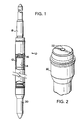
- the fuel rod for a nuclear fuel assembly and generally designated 10.
- the fuel rod comprises an elongated tube 12 containing a plurality of nuclear fuel pellets 14 stacked one on top of the other. Adjacent the upper end of the rod 10 is a plenum containing a spring 16 bearing against the pellets 14 and also defining a plenum for gas expansion within the fuel rod.
- the opposite ends of the fuel rod are closed by upper and lower end plugs 18 and 20, respectively.
- the end plugs are welded to the opposite ends of the tube 12 and seal the tubes.
- very minute passages or streamer holes may be provided, generally along the central axis of the end plugs as a result of certain end plug fabricating techniques. While the possibility that such streamer openings or passages may exist is quite remote, it is desirable to eliminate even that possibility.
- a small spot weld is formed coincident with the axial center line of the inside end face of the end plugs to seal any potential streamer opening by melting and solidifying the material, i.e., Zircaloy, of the end plug along its inner surface.
- a spot weld is indicated at 22 in Figure 2. Accordingly, should a streamer opening be extant through the end plug 18 or 20, the spot weld 22 seals the end of the opening, thus ensuring that the end plug forms an end seal for the fuel rod 10.
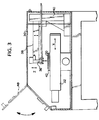
- FIG. 3 to 6 there is illustrated an automated laser welding system for applying center line welds to the interior ends of the fuel rod end plugs.
- X-Y positioning tables 32 and 34 respectively, below a laser 36 mounted for vertical movement in the Z direction.
- the laser 36 is cantilevered over the X-Y positioning tables 32 and 34, respectively, by a support arm 38 movable vertically along a support column 40.
- X-Y positioning tables are well known in the art and, accordingly, the drives and control systems for the drives are not specifically disclosed.
- the end plugs are presented to the laser 36 in pallets, preferably formed of stainless steel.
- the pallets are manually installed in the weld box 30 and pinned to one of the X-Y positioning tables.
- Each pallet 42 has a plurality of upwardly opening apertures 44 for receiving an end plug.
- the openings 44 are complementary in shape to the end plugs and thus accurately position the end plugs along the pallet and relative to the laser head 36 by pinning the pallet to one of the X-Y positioning tables.
- a plurality of end plugs typically of a specified type, are arranged in an array, for example, a 12x12 array thereof, on the pallet 42.
- the pallet Under computer control, the pallet is displaced by movement of the X-Y positioning tables to locate the interior end face 46 of each end plug in succession below the laser such that the laser can form a spot weld on the end face 46.
- the locating pins for the pallets may comprise two or more through openings in the pallets which can then be pinned to an underlying support of one of the X-Y positioning tables.
- Each pallet will have a unique bar code to facilitate identification by the system control of the pallet and type of end plug being welded.
- the weld box 30 is initially flooded with an inert gas, preferably argon, and an oxygen monitor system, not shown, is used to assure that the oxygen content in the weld box is below a specific welding limit.
- an oxygen monitor system not shown
- the control system also reads the bar code on the pallet and communicates with an appropriate database to determine the type of plugs loaded onto the pallet. Once the type of plug is known, the laser welder focus head is positioned over a first end plug in the pallet. When the plug has been identified as being in the correct location, the laser welder will apply a spot weld along the center line of the interior end face of the end plug.
- the control system indexes the X-Y positioning slides or tables so that the next plug is aligned with the laser. Succeeding end plugs are similarly welded. It will be appreciated that the spot weld is applied to the end face substantially along the axial center line and does not extend to any great extent radially outwardly of the center line. If larger welds are desired, multiple weld pulses can be provided while circularly rotating the X-Y slide. That is, the X and Y slides can be stepped to achieve a substantial circular pattern of welds, while a single end plug underlies the laser. Using laser welds results in no discernible distortions of the end plugs and no corrosion or defects appear over the spot weld region.
- the preferred embodiment of the present invention employs a 350 watt laser to form a 1/10-inch spot weld to a depth of.022 inches sufficient to seal and maintain sealed any streamer openings or passages formed generally along the axis of the end plugs.
Landscapes
- Engineering & Computer Science (AREA)
- Physics & Mathematics (AREA)
- Plasma & Fusion (AREA)
- General Engineering & Computer Science (AREA)
- High Energy & Nuclear Physics (AREA)
- Manufacturing & Machinery (AREA)
- Laser Beam Processing (AREA)
Applications Claiming Priority (2)
| Application Number | Priority Date | Filing Date | Title |
|---|---|---|---|
| US08/613,488 US5748691A (en) | 1996-03-11 | 1996-03-11 | Apparatus and methods for sealing end plugs for nuclear fuel rods |
| US613488 | 1996-03-11 |
Publications (2)
| Publication Number | Publication Date |
|---|---|
| EP0795876A2 true EP0795876A2 (fr) | 1997-09-17 |
| EP0795876A3 EP0795876A3 (fr) | 1998-04-22 |
Family
ID=24457515
Family Applications (1)
| Application Number | Title | Priority Date | Filing Date |
|---|---|---|---|
| EP97301259A Withdrawn EP0795876A3 (fr) | 1996-03-11 | 1997-02-26 | Dispositif et procédé pour sceller des bouchons d'extrémité des barres de combustible nucléaire |
Country Status (3)
| Country | Link |
|---|---|
| US (1) | US5748691A (fr) |
| EP (1) | EP0795876A3 (fr) |
| JP (1) | JPH102978A (fr) |
Families Citing this family (2)
| Publication number | Priority date | Publication date | Assignee | Title |
|---|---|---|---|---|
| KR100391178B1 (ko) * | 1999-12-29 | 2003-07-12 | 한국전력공사 | 핵 연료봉 인출 장치의 회전식 다기능 인출 헤드 |
| FR2805075B1 (fr) * | 2000-02-15 | 2002-05-10 | Franco Belge Combustibles | Procede de controle d'une operation de fermeture etanche par soudage de l'extremite d'un canal de remplissage traversant le bouchon superieur d'un crayon de combustible nucleaire |
Family Cites Families (23)
| Publication number | Priority date | Publication date | Assignee | Title |
|---|---|---|---|---|
| GB946344A (en) * | 1961-06-13 | 1964-01-08 | Atomic Energy Authority Uk | Improvements in or relating to brazing end closures to tubular members |
| BE620101A (fr) * | 1961-07-18 | |||
| FR1385866A (fr) * | 1964-03-03 | 1965-01-15 | Atomic Energy Authority Uk | Cartouche de combustible de réacteur nucléaire |
| GB1094564A (en) * | 1964-04-07 | 1967-12-13 | Atomic Energy Authority Uk | Nuclear reactor fuel elements |
| GB1108018A (en) * | 1964-07-31 | 1968-03-27 | Euratom | A process for welding composite metal-oxide materials such as sintered aluminium powder (s.a.p.) |
| US3378458A (en) * | 1965-10-19 | 1968-04-16 | Gen Electric | Nuclear reactor fuel element |
| US3528166A (en) * | 1967-04-14 | 1970-09-15 | Euratom | Process for the welding of metal objects |
| US3836431A (en) * | 1971-05-04 | 1974-09-17 | Belgonucleaire Sa | Nuclear fuel rods having end plugs with bores therethrough sealed by frangible membranes |
| NL7413871A (en) * | 1974-08-14 | 1976-02-17 | Cen Centre Energie Nucleaire | Fuel element pencil end cap construction - uses ball insert and projection welding against leakage |
| JPS54124186A (en) * | 1978-03-22 | 1979-09-26 | Toshiba Corp | Fuel element |
| US4230930A (en) * | 1979-01-25 | 1980-10-28 | Ford Motor Company | Laser welding method for electrical wire connection to a terminal pin of an exhaust gas sensor |
| US4541055A (en) * | 1982-09-01 | 1985-09-10 | Westinghouse Electric Corp. | Laser machining system |
| JPS60201283A (ja) * | 1984-03-27 | 1985-10-11 | 原子燃料工業株式会社 | 原子炉用燃料棒 |
| US4865804A (en) * | 1984-05-02 | 1989-09-12 | Westinghouse Electric Corp. | Fuel rod end plug |
| US4921663A (en) * | 1988-06-06 | 1990-05-01 | Westinghouse Electric Corp. | End plug weld for nuclear fuel rod |
| DE59006143D1 (de) * | 1989-12-27 | 1994-07-21 | Sulzer Ag | Vorrichtung zum Schweissen und/oder Beschichten von Werkstücken, Düse für eine derartige Vorrichtung sowie Manipulator für die Düse einer derartigen Vorrichtung. |
| US5140128A (en) * | 1990-05-03 | 1992-08-18 | General Electric Company | Method and system for providing elements of composite objects |
| US5171963A (en) * | 1990-05-21 | 1992-12-15 | Ntn Corporation | Laser processing device and laser processing method |
| US5158740A (en) * | 1991-08-05 | 1992-10-27 | Westinghouse Electric Corp. | Fuel rod end plug welding method |
| WO1993006963A1 (fr) * | 1991-09-30 | 1993-04-15 | Nippei Toyama Corporation | Appareil et procede d'usinage par laser |
| JPH07244179A (ja) * | 1994-03-07 | 1995-09-19 | Nuclear Fuel Ind Ltd | 燃料棒の上部端栓 |
| US5966980A (en) * | 1994-09-29 | 1999-10-19 | General Electric Company | Method for fabricating end plugs for nuclear fuel rods |
| JPH08313666A (ja) * | 1995-05-17 | 1996-11-29 | Nuclear Fuel Ind Ltd | 核燃料要素 |
-
1996
- 1996-03-11 US US08/613,488 patent/US5748691A/en not_active Expired - Fee Related
-
1997
- 1997-02-26 EP EP97301259A patent/EP0795876A3/fr not_active Withdrawn
- 1997-03-11 JP JP9055904A patent/JPH102978A/ja not_active Withdrawn
Also Published As
| Publication number | Publication date |
|---|---|
| EP0795876A3 (fr) | 1998-04-22 |
| US5748691A (en) | 1998-05-05 |
| JPH102978A (ja) | 1998-01-06 |
Similar Documents
| Publication | Publication Date | Title |
|---|---|---|
| US5158740A (en) | Fuel rod end plug welding method | |
| US4572816A (en) | Reconstituting a nuclear reactor fuel assembly | |
| EP0154229B1 (fr) | Assemblage de combustible pour réacteur nucléaire | |
| JPH02211990A (ja) | 薄肉管状部品に複雑な形状の開口を機械加工するための装置 | |
| US5809098A (en) | Method for sealing a stub tube in a nuclear reactor | |
| EP0795876A2 (fr) | Dispositif et procédé pour sceller des bouchons d'extrémité des barres de combustible nucléaire | |
| US5345488A (en) | Nuclear fuel rod having concave weld across pressurization hole in end plug | |
| JPH0536140B2 (fr) | ||
| JPH02198390A (ja) | 燃料バンドル用スペーサの製造方法 | |
| CN114944234B (zh) | 一种端塞包壳一体化环形燃料棒及燃料组件 | |
| US7971330B2 (en) | Method of repairing a nuclear reactor vessel bottom head penetration | |
| US4678924A (en) | Method of setting a stop means inside of a tubular element | |
| US20030016777A1 (en) | TIG welded MOX fuel rod | |
| US4660270A (en) | Apparatus and method for applying an end plug to a fuel rod tube end | |
| JPS6247634B2 (fr) | ||
| EP0151920B1 (fr) | Procédé de traitement d'une barre de commande destinée à l'immersion dans un réfrigérant de réacteur nucléaire | |
| JPH0365876B2 (fr) | ||
| US5966980A (en) | Method for fabricating end plugs for nuclear fuel rods | |
| JPH02102494A (ja) | 原子炉圧力容器の補修方法 | |
| CN111696691B (zh) | 保护管组件底部与核燃料组件配合面的检查方法及装置 | |
| BAIN et al. | CANDU FUEL | |
| King | Pressurization of nuclear fuel rods using laser welding | |
| Dalmastri et al. | Experiments on fabrication of fuel elements for fast reactors | |
| Adamson Jr | FABRICATION PROCEDURES FOR THE INITIAL HIGH FLUX ISOTOPE REACTOR FUEL ELEMENTS. | |
| JPH07244179A (ja) | 燃料棒の上部端栓 |
Legal Events
| Date | Code | Title | Description |
|---|---|---|---|
| PUAI | Public reference made under article 153(3) epc to a published international application that has entered the european phase |
Free format text: ORIGINAL CODE: 0009012 |
|
| AK | Designated contracting states |
Kind code of ref document: A2 Designated state(s): DE ES SE |
|
| PUAL | Search report despatched |
Free format text: ORIGINAL CODE: 0009013 |
|
| RHK1 | Main classification (correction) |
Ipc: G21C 3/10 |
|
| AK | Designated contracting states |
Kind code of ref document: A3 Designated state(s): DE ES SE |
|
| 17P | Request for examination filed |
Effective date: 19981022 |
|
| 17Q | First examination report despatched |
Effective date: 19990702 |
|
| APBT | Appeal procedure closed |
Free format text: ORIGINAL CODE: EPIDOSNNOA9E |
|
| STAA | Information on the status of an ep patent application or granted ep patent |
Free format text: STATUS: THE APPLICATION IS DEEMED TO BE WITHDRAWN |
|
| 18D | Application deemed to be withdrawn |
Effective date: 20040901 |
|
| APAF | Appeal reference modified |
Free format text: ORIGINAL CODE: EPIDOSCREFNE |