EP0795906A2 - Elektronischer Schaltungsaufbau und seine Herstellung - Google Patents
Elektronischer Schaltungsaufbau und seine Herstellung Download PDFInfo
- Publication number
- EP0795906A2 EP0795906A2 EP97104269A EP97104269A EP0795906A2 EP 0795906 A2 EP0795906 A2 EP 0795906A2 EP 97104269 A EP97104269 A EP 97104269A EP 97104269 A EP97104269 A EP 97104269A EP 0795906 A2 EP0795906 A2 EP 0795906A2
- Authority
- EP
- European Patent Office
- Prior art keywords
- holes
- substrate
- solder
- substrates
- electronic
- Prior art date
- Legal status (The legal status is an assumption and is not a legal conclusion. Google has not performed a legal analysis and makes no representation as to the accuracy of the status listed.)
- Withdrawn
Links
Images


Classifications
-
- H—ELECTRICITY
- H10—SEMICONDUCTOR DEVICES; ELECTRIC SOLID-STATE DEVICES NOT OTHERWISE PROVIDED FOR
- H10W—GENERIC PACKAGES, INTERCONNECTIONS, CONNECTORS OR OTHER CONSTRUCTIONAL DETAILS OF DEVICES COVERED BY CLASS H10
- H10W90/00—Package configurations
-
- H—ELECTRICITY
- H05—ELECTRIC TECHNIQUES NOT OTHERWISE PROVIDED FOR
- H05K—PRINTED CIRCUITS; CASINGS OR CONSTRUCTIONAL DETAILS OF ELECTRIC APPARATUS; MANUFACTURE OF ASSEMBLAGES OF ELECTRICAL COMPONENTS
- H05K3/00—Apparatus or processes for manufacturing printed circuits
- H05K3/36—Assembling printed circuits with other printed circuits
- H05K3/361—Assembling flexible printed circuits with other printed circuits
- H05K3/363—Assembling flexible printed circuits with other printed circuits by soldering
-
- H—ELECTRICITY
- H05—ELECTRIC TECHNIQUES NOT OTHERWISE PROVIDED FOR
- H05K—PRINTED CIRCUITS; CASINGS OR CONSTRUCTIONAL DETAILS OF ELECTRIC APPARATUS; MANUFACTURE OF ASSEMBLAGES OF ELECTRICAL COMPONENTS
- H05K1/00—Printed circuits
- H05K1/02—Details
- H05K1/0266—Marks, test patterns or identification means
- H05K1/0269—Marks, test patterns or identification means for visual or optical inspection
-
- H—ELECTRICITY
- H05—ELECTRIC TECHNIQUES NOT OTHERWISE PROVIDED FOR
- H05K—PRINTED CIRCUITS; CASINGS OR CONSTRUCTIONAL DETAILS OF ELECTRIC APPARATUS; MANUFACTURE OF ASSEMBLAGES OF ELECTRICAL COMPONENTS
- H05K1/00—Printed circuits
- H05K1/02—Details
- H05K1/14—Structural association of two or more printed circuits
- H05K1/144—Stacked arrangements of planar printed circuit boards
-
- H—ELECTRICITY
- H05—ELECTRIC TECHNIQUES NOT OTHERWISE PROVIDED FOR
- H05K—PRINTED CIRCUITS; CASINGS OR CONSTRUCTIONAL DETAILS OF ELECTRIC APPARATUS; MANUFACTURE OF ASSEMBLAGES OF ELECTRICAL COMPONENTS
- H05K2201/00—Indexing scheme relating to printed circuits covered by H05K1/00
- H05K2201/04—Assemblies of printed circuits
- H05K2201/041—Stacked PCBs, i.e. having neither an empty space nor mounted components in between
-
- H—ELECTRICITY
- H05—ELECTRIC TECHNIQUES NOT OTHERWISE PROVIDED FOR
- H05K—PRINTED CIRCUITS; CASINGS OR CONSTRUCTIONAL DETAILS OF ELECTRIC APPARATUS; MANUFACTURE OF ASSEMBLAGES OF ELECTRICAL COMPONENTS
- H05K2201/00—Indexing scheme relating to printed circuits covered by H05K1/00
- H05K2201/09—Shape and layout
- H05K2201/09209—Shape and layout details of conductors
- H05K2201/09372—Pads and lands
- H05K2201/094—Array of pads or lands differing from one another, e.g. in size, pitch or thickness; Using different connections on the pads
-
- H—ELECTRICITY
- H05—ELECTRIC TECHNIQUES NOT OTHERWISE PROVIDED FOR
- H05K—PRINTED CIRCUITS; CASINGS OR CONSTRUCTIONAL DETAILS OF ELECTRIC APPARATUS; MANUFACTURE OF ASSEMBLAGES OF ELECTRICAL COMPONENTS
- H05K2201/00—Indexing scheme relating to printed circuits covered by H05K1/00
- H05K2201/09—Shape and layout
- H05K2201/09209—Shape and layout details of conductors
- H05K2201/095—Conductive through-holes or vias
- H05K2201/09536—Buried plated through-holes, i.e. plated through-holes formed in a core before lamination
-
- H—ELECTRICITY
- H05—ELECTRIC TECHNIQUES NOT OTHERWISE PROVIDED FOR
- H05K—PRINTED CIRCUITS; CASINGS OR CONSTRUCTIONAL DETAILS OF ELECTRIC APPARATUS; MANUFACTURE OF ASSEMBLAGES OF ELECTRICAL COMPONENTS
- H05K2201/00—Indexing scheme relating to printed circuits covered by H05K1/00
- H05K2201/09—Shape and layout
- H05K2201/09209—Shape and layout details of conductors
- H05K2201/095—Conductive through-holes or vias
- H05K2201/096—Vertically aligned vias, holes or stacked vias
-
- H—ELECTRICITY
- H05—ELECTRIC TECHNIQUES NOT OTHERWISE PROVIDED FOR
- H05K—PRINTED CIRCUITS; CASINGS OR CONSTRUCTIONAL DETAILS OF ELECTRIC APPARATUS; MANUFACTURE OF ASSEMBLAGES OF ELECTRICAL COMPONENTS
- H05K2201/00—Indexing scheme relating to printed circuits covered by H05K1/00
- H05K2201/10—Details of components or other objects attached to or integrated in a printed circuit board
- H05K2201/10613—Details of electrical connections of non-printed components, e.g. special leads
- H05K2201/10621—Components characterised by their electrical contacts
- H05K2201/10666—Plated through-hole for surface mounting on PCB
-
- H—ELECTRICITY
- H05—ELECTRIC TECHNIQUES NOT OTHERWISE PROVIDED FOR
- H05K—PRINTED CIRCUITS; CASINGS OR CONSTRUCTIONAL DETAILS OF ELECTRIC APPARATUS; MANUFACTURE OF ASSEMBLAGES OF ELECTRICAL COMPONENTS
- H05K2201/00—Indexing scheme relating to printed circuits covered by H05K1/00
- H05K2201/10—Details of components or other objects attached to or integrated in a printed circuit board
- H05K2201/10613—Details of electrical connections of non-printed components, e.g. special leads
- H05K2201/10621—Components characterised by their electrical contacts
- H05K2201/10681—Tape Carrier Package [TCP]; Flexible sheet connector
-
- H—ELECTRICITY
- H05—ELECTRIC TECHNIQUES NOT OTHERWISE PROVIDED FOR
- H05K—PRINTED CIRCUITS; CASINGS OR CONSTRUCTIONAL DETAILS OF ELECTRIC APPARATUS; MANUFACTURE OF ASSEMBLAGES OF ELECTRICAL COMPONENTS
- H05K3/00—Apparatus or processes for manufacturing printed circuits
- H05K3/30—Assembling printed circuits with electric components, e.g. with resistors
- H05K3/32—Assembling printed circuits with electric components, e.g. with resistors electrically connecting electric components or wires to printed circuits
- H05K3/34—Assembling printed circuits with electric components, e.g. with resistors electrically connecting electric components or wires to printed circuits by soldering
- H05K3/346—Solder materials or compositions specially adapted therefor
-
- H—ELECTRICITY
- H05—ELECTRIC TECHNIQUES NOT OTHERWISE PROVIDED FOR
- H05K—PRINTED CIRCUITS; CASINGS OR CONSTRUCTIONAL DETAILS OF ELECTRIC APPARATUS; MANUFACTURE OF ASSEMBLAGES OF ELECTRICAL COMPONENTS
- H05K3/00—Apparatus or processes for manufacturing printed circuits
- H05K3/46—Manufacturing multilayer circuits
- H05K3/4611—Manufacturing multilayer circuits by laminating two or more circuit boards
- H05K3/4614—Manufacturing multilayer circuits by laminating two or more circuit boards the electrical connections between the circuit boards being made during lamination
-
- H—ELECTRICITY
- H10—SEMICONDUCTOR DEVICES; ELECTRIC SOLID-STATE DEVICES NOT OTHERWISE PROVIDED FOR
- H10W—GENERIC PACKAGES, INTERCONNECTIONS, CONNECTORS OR OTHER CONSTRUCTIONAL DETAILS OF DEVICES COVERED BY CLASS H10
- H10W72/00—Interconnections or connectors in packages
- H10W72/071—Connecting or disconnecting
- H10W72/072—Connecting or disconnecting of bump connectors
- H10W72/07251—Connecting or disconnecting of bump connectors characterised by changes in properties of the bump connectors during connecting
-
- H—ELECTRICITY
- H10—SEMICONDUCTOR DEVICES; ELECTRIC SOLID-STATE DEVICES NOT OTHERWISE PROVIDED FOR
- H10W—GENERIC PACKAGES, INTERCONNECTIONS, CONNECTORS OR OTHER CONSTRUCTIONAL DETAILS OF DEVICES COVERED BY CLASS H10
- H10W72/00—Interconnections or connectors in packages
- H10W72/20—Bump connectors, e.g. solder bumps or copper pillars; Dummy bumps; Thermal bumps
-
- H—ELECTRICITY
- H10—SEMICONDUCTOR DEVICES; ELECTRIC SOLID-STATE DEVICES NOT OTHERWISE PROVIDED FOR
- H10W—GENERIC PACKAGES, INTERCONNECTIONS, CONNECTORS OR OTHER CONSTRUCTIONAL DETAILS OF DEVICES COVERED BY CLASS H10
- H10W90/00—Package configurations
- H10W90/20—Configurations of stacked chips
- H10W90/22—Configurations of stacked chips the stacked chips being on both top and bottom sides of a package substrate, interposer or RDL
-
- H—ELECTRICITY
- H10—SEMICONDUCTOR DEVICES; ELECTRIC SOLID-STATE DEVICES NOT OTHERWISE PROVIDED FOR
- H10W—GENERIC PACKAGES, INTERCONNECTIONS, CONNECTORS OR OTHER CONSTRUCTIONAL DETAILS OF DEVICES COVERED BY CLASS H10
- H10W90/00—Package configurations
- H10W90/20—Configurations of stacked chips
- H10W90/288—Configurations of stacked chips characterised by arrangements for thermal management of the stacked chips
-
- H—ELECTRICITY
- H10—SEMICONDUCTOR DEVICES; ELECTRIC SOLID-STATE DEVICES NOT OTHERWISE PROVIDED FOR
- H10W—GENERIC PACKAGES, INTERCONNECTIONS, CONNECTORS OR OTHER CONSTRUCTIONAL DETAILS OF DEVICES COVERED BY CLASS H10
- H10W90/00—Package configurations
- H10W90/20—Configurations of stacked chips
- H10W90/297—Configurations of stacked chips characterised by the through-semiconductor vias [TSVs] in the stacked chips
-
- H—ELECTRICITY
- H10—SEMICONDUCTOR DEVICES; ELECTRIC SOLID-STATE DEVICES NOT OTHERWISE PROVIDED FOR
- H10W—GENERIC PACKAGES, INTERCONNECTIONS, CONNECTORS OR OTHER CONSTRUCTIONAL DETAILS OF DEVICES COVERED BY CLASS H10
- H10W90/00—Package configurations
- H10W90/701—Package configurations characterised by the relative positions of pads or connectors relative to package parts
- H10W90/721—Package configurations characterised by the relative positions of pads or connectors relative to package parts of bump connectors
Definitions
- the present invention relates to an electronic-circuit assembly, and more particularly to an electronic asemmbly having a plurality of substrates which are stacked.
- Fig. 7-7 of the reference two ceramic substrates are stacked in this technique. These ceramic substrates are connected to each other by soldering pins protruding from a lower surface of an upper substrate to an upper surface of a lower substrate.
- one object of the present invention is to provide a mounting structure of electronic parts whose connection state between substrates is easily checked.
- Another object of the present invention is to provide a mounting structure of electronic parts whose design can be changed in a short time.
- Yet another object of the present invention is to provide a method of reducing a length of connection wire between electronic parts.
- an electronic-circuit assembly comprises a plurality of stacked substrates having through-holes respectively and a connection member having electric conductivity and connecting adjacent through-holes of said substrates to each other in the stack direction of said substrates.
- the electronic-circuit assembly may further comprising a wiring substrate, said wiring substrate including a first surface on which said plurality of substrates are mounted, and terminals provided on said first surface and connected to said through-holes in the lowest one of said plurality of substrates by said connection member.
- the electronic-circuit assembly wherein said plurality of substrates includes conductive pads which are provided on upper and lower surfaces of said substrates, surround said through-holes, and are connected to said through-holes of said substrate and wherein connections between said plurality of substrates are made by connecting said conductive pads to each other by said connection member in said plurality of substrates.
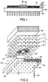
- a first embodiment of an electronic-circuit assembly of the present invention includes a wiring substrate 30 and a plurality of film carriers 1 mounted on the wiring substrate 30.
- Fig. 1 shows four layers of film carriers 1a to 1d, the number of the layers for the film carriers 1 is not limited.
- the film carriers 1a, 1b, 1c and 1d are stacked. Adjacent two of the film carriers 1 in the stack direction are connected to each other in a connection structure described below.
- an LSI chip 20 is mounted. On a circuit surface of the LSI chip 20 is coated with plastic mold resin 22. Between adjacent two of the LSI chips 20 in the stack direction, heating plates, which are not shown, are provided. The heating plates are formed of good thermal conductivity materials such as copper-tungsten alloy.
- On a lower surface of the wiring substrate 30, a plurality of input-output pins 50 are provided.
- each of film carriers 1 includes a flexible film 10.
- the flexible film 10 is made of insulating materials such as polyimide or epoxy resin.
- the flexible film 10 has pliability and has a form of a square having each side of approximately 50 mm.
- the thickness of the flexible film 10 is approximately 50 ⁇ m.
- a device hole for containing the LSI chip 20 is provided in the central portion of the flexible film 10.
- a plurality of through-holes 12 are arranged in a lattice. Each distance in the lattice is approximately 1.27 mm.
- a diameter of each through-hole 12 is approximately 100 ⁇ m.
- lands 13 of conductive materials are provided around the through-hole 12 and on the inner surface thereof. A diameter of each land 13 is approximately 300 ⁇ m.
- a circuit pattern 11 is provided on the flexible film 10.
- a wire width of the circuit pattern 11 is approximately 50 ⁇ m.
- the circuit pattern 11 connects the plurality of through-holes 12 and a plurality of beam leads 14 respectively.
- One ends of the circuit pattern 11 are connected to through-holes 12.
- Another ends of the circuit pattern 11 is connected to one ends of each beam leads 14 on a circumferential edge of the device hole.
- the other ends of the beam leads 14, which is protruding to an inside the device hole, are connected to a pad of the LSI chip 20.
- TAB tape automated bonding
- the wiring substrate 30 is epoxy resin or polyimide reinforced with glass fiber.
- the wiring substrate 30 has a shape of a square having each side of approximately 60 mm.
- the wiring substrate 30 has a thickness of approximately 2.5 mm and high rigidity.
- the wiring substrate 30 is a multi-layer wiring substrate. Ground circuit layers 34 and 36 and power supply source circuit layers 35 and 37 are provided in the inside of the wiring substrate 30.
- a plurality of pads 31 are provided on the upper surface of the wiring substrate 30, a plurality of pads 31 are provided.
- the pads 31 are arranged in positions corresponding to the through-holes 12 of the film carriers 1.
- the pads 31 are arranged in a lattice. Each distance of the lattice is approximately 1.27 mm. Areas, which the pads 31 do not provided, on the upper surface of the wiring substrate 30 are coated with solder resist 32.
- a plurality of input-output pins 50 are provided on the lower surface of the wiring substrate 30, a plurality of input-output pins 50 are provided.
- the input-output pins 50 are arranged in a lattice. Each distance of the lattice is approximately 1.27 mm.
- the input-output pins 50 are connected to the mother board.
- the length of the wiring between the LSI chips and the mother board can be reduced to the minimum by using the input-output pins 50 provided directly under the LSI chips 20 or around them. Since the input-output pins 50 are arranged on the entire lower surface of the wiring substrate 30.
- respective ends of the input-output pins 50 is inserted into respective hole portions 38 on the wiring substrate 30.
- An inserted portion of respective the input-output pins 50 are coated with insulating coating 55.
- the input-output pins 50 are selectively connected to the internal circuit layers of the wiring substrate 30.
- the removed portions of the insulating coating 55 there are provided three types of input-output pins 51 to 53.
- the input-output pin 51 has a removed portion at the top of the insulating coating 55. Therefore, the input-output pin 51 is connected to the power supply source circuit layer 35.
- the input-output pin 52 has a removed portion in the lower part of the insulating coating 55. Therefore, the input-output pin 52 is connected to the power supply source circuit layer 37.
- the input-output pin 53 has a removed portion in the middle part of the insulating coating 55. Therefore, the input-output pin 53 is connected to the ground circuit layer 36. In this manner, the internal circuit layers of the wiring substrate 30 can be selectively connected to the input-output pins 50.
- the wiring substrate 30 has through-holes for signal pins. Pins are inserted into the through-holes for the signal pins without insulating coating.
- a heat sink 60 for heat dissipation is installed on the LSI chip 20 which is mounted on the topmost film carrier 1d.
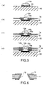
- the through-holes 12a to 12d of the film carriers 1a to 1d are positioned in a straight line on the pad 31 on the wiring substrate 30.
- the through-holes 12a to 12d are connected by solder 15.
- the through-holes 12a to 12d are filled with the solder 15.
- the solder 15 is positioned on the pad 31 of the wiring substrate 30 in a first step. For example, printing is made with creamy solder 15 on the pad 31.
- the stacked film carriers 1a and 1b are positioned on the solder 15 in a second step.
- the solder 15 is heated in a third step.
- the solder 15 melts and a part of it is sucked inside the through-holes 12a and 12b. After that, the solder 15 is cooled down so as to connect the pad 31 with the through-holes 12a and 12b.
- solder 15a is positioned on the pad 31 in a first step.
- a through-hole 12a of a film carrier 1a is connected to the pad 31 in the same manner as for Figs. 4(b) and 4(c) in a second step.
- solder 15b is positioned on the solder 15a in a third step.
- a melting point of the solder 15b is lower than that of the solder 15a.
- a through-hole 12b of a film carrier 1b is connected to the through-hole 12a in the same manner as for Figs. 4(b) and 4(c) in a fourth step.
- a heating temperature of the solder 15b is lower than the melting point of the solder 15a. Therefore, the solder 15a does not melt in the fourth step.
- connection state between the through-holes 12a and 12b can be easily checked. Specifically, it is only required to check that the solder 15 appears inside the topmost through-hole 12b. It can be checked only with viewing the film carrier 1b from the upward position.
- the LSI chip 20 has each side of 20 mm, that the LSI chip 20, the heat conductive plate, and the plastic mold resin have a height of 1 mm in total, that the LSI chips 20 are stacked at 2-mm intervals, that the film carrier 1 has each side of 50 mm, and that four LSI chips 20 are mounted on a single film carrier 1, 16 LSI chips 20 are arranged within a region of a quadrangular prism having each side of 40 mm and a height of 4 mm.
- a circuit region of the LSI chips 20 has a form of a quadrangular prism having each side of 50 mm and a height of 4 mm. Therefore, when the LSI chips 20 are connected to each other by means of three-dimensional orthogonal-system circuit, the wire between the farthest LSI chips 20 has a length of 104 mm or less.
- a mounting area of the LSI chips 20 has a form of a square having each side of 80 mm.
- the wire for connection between the LSI chips 20 spaced farthest to each other has a length of approximately 160 mm. In this manner, the length of the wire between the LSI chips 20 can be reduced according to the present invention.
- the second embodiment is characterized by a structure of through-holes 12. Other structures are essentially the same as for the first embodiment.
- each of the through-holes 12 of the second embodiment has a tapered inner surface.
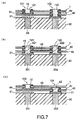
- the third embodiment of the present invention is characterized by a point that it includes a design change film carrier so as to simplify the design changes. Other structures are essentially the same as for the first embodiment.
- a disconnection means, a connection means, and a switching means are appropriately arranged so as to achieve a desired design change by a combination of these means.
- the disconnection means for a design change film carrier 4a is achieved by means of not providing a through-hole.
- a film carrier 1 has a through-hole 121 at a lattice point 101.
- the design change film carrier 4a does not have any through-hole at the lattice point 101 so as to have an insulation between an upper surface of the design change film carrier 4a and a lower surface thereof.
- a land 41 is arranged instead of a through-hole.
- the land 41 is connected to a through-hole 121 of the film carrier 1 by means of solder. In this manner, a signal through-hole 33 is electrically disconnected from the through-hole 121.
- Materials, a size, and a shape of a flexible film 40 of the design change film carrier 4 may be the same as for the flexible film 10.
- a connection means of a design change film carrier 4b is achieved by a circuit pattern 43 arranged on the design change film carrier 4b.
- the circuit pattern 43 connects a through-hole 421 of the design change film carrier 4b to a through-hole 422 therefor.
- a signal through-hole 331 is connected to a signal through-hole 332.
- a switching means for a design change film carrier 4c is achieved by a combination between the disconnection means and the connection means.
- the film carrier 1 has a through-hole 12 at a lattice point 103.
- the design change film carrier 4c does not have any through-hole at the lattice point 103. Therefore, the through-hole 12 is electrically disconnected from a signal through-hole 331.
- a land 44 is provided instead of a through-hole.
- the land 44 is connected to a through-hole 42 via a circuit pattern 43.
- a through-pole 42 is positioned at a lattice point 104 which is different from the point of the through-hole 12.
- the through-hole 42 is connected to the signal through-hole 332. In this manner, the through-hole 12 which should originally be connected to the signal through-hole 331 can be switched to the signal through-hole 332.
- the design change film carrier 4 can be made in a shorter time in comparison with a multi-layer wiring substrate. Accordingly, a design for an electronic-circuit assembly can be changed in a short time. At present, the design change film carrier 4 can be made in two or three days.
- respective film carriers are connected to each other only by means of soldering between lands arranged around through-holes on upper and lower surfaces of respective film carriers. Accordingly, the design change film carrier 4 can be inserted by melting the solder to separate respective film carriers 12. In addition, the design change film carrier 4 can be made in a short time.
- the design change film carrier 4 is arranged between the wiring substrate 30 and the lowest film carrier 1. It is, however, possible to arrange the design change film carrier 4 in other positions between layers. In addition, it is also possible to use a plurality of design change film carriers 4.
- this embodiment is characterized by a supporting member 61 for supporting the heat sink 60.
- Other structures are essentially the same as for the first embodiment.
- the supporting member 61 has a pillar-shaped foot portion and a plate portion arranged on the foot portion.
- the foot portion of the supporting member 61 is inserted into holes on the flexible film 10 so as to be fixed to the wiring substrate 30.
- the LSI chip 20 of the topmost film carrier 1 is brought into a contact with a lower surface of the plate portion of the supporting member 61.
- the plate portion has holes for containing the topmost through-holes 12. These holes prevent electric contacts between the through-holes 12 and the plate portions.
- the heat sink 60 is installed on the upper surface of the supporting member 61.
- a gap between adjacent flexible films 10 can be filled with resin.
- a gap between the supporting member 61 and the topmost flexible film 10 can be filled with resin. It is preferable that the resin has both of insulation quality and good heat conductivity.
- each LSI chip 20 heat generated from each LSI chip 20 is conducted to the topmost LSI chip 20 via a heat conductive plate arranged between the LSI chips 20.
- the heat conducted to the topmost LSI chip 20 is conducted to the heat sink 60 via a plate portion of the supporting member 61.
- the heat conducted to the heat sink 60 is discharged to the outside air.
- the heat sink 60 is supported by the supporting member 61 and therefore a weight of the heat sink 60 is not weighted to the LSI chips 20. Accordingly, reliability of the LSI chips 20 is not reduced when a large-sized heat sink 60 is used.
- the foot portion of the supporting member 61 serves as a guide of the film carriers 1.
- a plurality of LSI chips 20 can be mounted on a single film carrier 1. Additionally, it is also possible to combine the above-described characteristics of respective embodiments.
- the LSI chips 20 are mounted on the film carriers 1 and a plurality of the film carriers 1 are stacked into a stack in the present invention.
- the film carriers 1 are connected by soldering the through-holes 12 arranged on the film carriers 1.
- a design change can be achieved by putting the design change film carrier 4 between the film carriers 1.
- connection state between the film carriers 1 can be easily checked. Specifically, it is only required to check visually that solder appears inside the topmost through-hole 12.
- a design can be changed in a short time. Specifically, it is only required to insert a design change film carrier 4.
- the design change film carrier 4 can be made in a short time.
- wiring lengths for connection between electronic parts can be reduced. It is because the electronic parts are three-dimensionally mounted.
Landscapes
- Engineering & Computer Science (AREA)
- Manufacturing & Machinery (AREA)
- Microelectronics & Electronic Packaging (AREA)
- Combinations Of Printed Boards (AREA)
- Production Of Multi-Layered Print Wiring Board (AREA)
- Cooling Or The Like Of Electrical Apparatus (AREA)
- Structure Of Printed Boards (AREA)
Applications Claiming Priority (2)
| Application Number | Priority Date | Filing Date | Title |
|---|---|---|---|
| JP55683/96 | 1996-03-13 | ||
| JP8055683A JP2820108B2 (ja) | 1996-03-13 | 1996-03-13 | 電子部品の実装構造およびその製造方法 |
Publications (2)
| Publication Number | Publication Date |
|---|---|
| EP0795906A2 true EP0795906A2 (de) | 1997-09-17 |
| EP0795906A3 EP0795906A3 (de) | 1998-07-22 |
Family
ID=13005709
Family Applications (1)
| Application Number | Title | Priority Date | Filing Date |
|---|---|---|---|
| EP97104269A Withdrawn EP0795906A3 (de) | 1996-03-13 | 1997-03-13 | Elektronischer Schaltungsaufbau und seine Herstellung |
Country Status (4)
| Country | Link |
|---|---|
| US (1) | US5892657A (de) |
| EP (1) | EP0795906A3 (de) |
| JP (1) | JP2820108B2 (de) |
| CA (1) | CA2199796C (de) |
Cited By (2)
| Publication number | Priority date | Publication date | Assignee | Title |
|---|---|---|---|---|
| EP0942636A3 (de) * | 1998-03-12 | 2001-03-14 | Lucent Technologies Inc. | Lötverbindungsverfahren einer Leiterplatte |
| WO2001015508A3 (en) * | 1999-08-20 | 2001-09-27 | Cardiac Pacemakers Inc | Integrated emi shield utilizing a hybrid edge |
Families Citing this family (16)
| Publication number | Priority date | Publication date | Assignee | Title |
|---|---|---|---|---|
| US6734545B1 (en) * | 1995-11-29 | 2004-05-11 | Hitachi, Ltd. | BGA type semiconductor device and electronic equipment using the same |
| US6462950B1 (en) * | 2000-11-29 | 2002-10-08 | Nokia Mobile Phones Ltd. | Stacked power amplifier module |
| DE10152475A1 (de) * | 2001-10-24 | 2003-05-08 | Hella Kg Hueck & Co | Wärmeleitendes Verbindungsstück |
| JP3826875B2 (ja) | 2002-10-29 | 2006-09-27 | セイコーエプソン株式会社 | 圧電デバイスおよびその製造方法 |
| US6657864B1 (en) * | 2002-12-16 | 2003-12-02 | International Business Machines Corporation | High density thermal solution for direct attach modules |
| JPWO2004112450A1 (ja) * | 2003-06-12 | 2006-07-20 | 富士通株式会社 | 基板実装方法及び実装構造 |
| US6974333B2 (en) * | 2004-03-30 | 2005-12-13 | General Electric Company | High-density connection between multiple circuit boards |
| JP2007273654A (ja) * | 2006-03-31 | 2007-10-18 | Sumitomo Bakelite Co Ltd | フレキシブル回路基板、フレキシブル回路基板の製造方法および電子機器 |
| US7926173B2 (en) * | 2007-07-05 | 2011-04-19 | Occam Portfolio Llc | Method of making a circuit assembly |
| KR101489034B1 (ko) * | 2008-12-19 | 2015-02-04 | 후루카와 덴키 고교 가부시키가이샤 | 다층 프린트 기판 및 그의 제조 방법 |
| JP5741105B2 (ja) | 2011-03-22 | 2015-07-01 | セイコーエプソン株式会社 | 電気光学装置 |
| KR102223784B1 (ko) * | 2014-06-03 | 2021-03-08 | 삼성디스플레이 주식회사 | 연성 회로 필름 및 이를 포함하는 표시 장치 |
| DE102014013565A1 (de) * | 2014-09-18 | 2016-03-24 | Plastic Electronic Gmbh | Schaltungsträgerfolie-Leiterplatten-Aufbau |
| JP6445220B1 (ja) * | 2017-05-30 | 2018-12-26 | 新電元工業株式会社 | 電子装置およびその製造方法 |
| US11257742B2 (en) * | 2020-07-02 | 2022-02-22 | Advanced Semiconductor Engineering, Inc. | Wiring structure and method for manufacturing the same |
| US11355426B2 (en) * | 2020-07-31 | 2022-06-07 | Advanced Semiconductor Engineering, Inc. | Wiring structure and method for manufacturing the same |
Family Cites Families (8)
| Publication number | Priority date | Publication date | Assignee | Title |
|---|---|---|---|---|
| JPS6447081U (de) * | 1987-09-16 | 1989-03-23 | ||
| US5128831A (en) * | 1991-10-31 | 1992-07-07 | Micron Technology, Inc. | High-density electronic package comprising stacked sub-modules which are electrically interconnected by solder-filled vias |
| ATE166202T1 (de) * | 1991-12-31 | 1998-05-15 | Tessera Inc | Verfahren zur konstruktion von mehrschichtigen schaltungen, strukturen mit personalisierungsmerkmalen und darin verwendete komponenten |
| JP2758099B2 (ja) * | 1992-02-27 | 1998-05-25 | シャープ株式会社 | 多層フレキシブルプリント配線板 |
| JP2748768B2 (ja) * | 1992-03-19 | 1998-05-13 | 株式会社日立製作所 | 薄膜多層配線基板およびその製造方法 |
| US5404044A (en) * | 1992-09-29 | 1995-04-04 | International Business Machines Corporation | Parallel process interposer (PPI) |
| JPH0766557A (ja) * | 1993-08-31 | 1995-03-10 | Mitsubishi Gas Chem Co Inc | リジッドフレキシブル多層プリント板の製造方法 |
| US5896276A (en) * | 1994-08-31 | 1999-04-20 | Nec Corporation | Electronic assembly package including connecting member between first and second substrates |
-
1996
- 1996-03-13 JP JP8055683A patent/JP2820108B2/ja not_active Expired - Fee Related
-
1997
- 1997-03-12 CA CA002199796A patent/CA2199796C/en not_active Expired - Fee Related
- 1997-03-13 US US08/816,671 patent/US5892657A/en not_active Expired - Fee Related
- 1997-03-13 EP EP97104269A patent/EP0795906A3/de not_active Withdrawn
Cited By (3)
| Publication number | Priority date | Publication date | Assignee | Title |
|---|---|---|---|---|
| EP0942636A3 (de) * | 1998-03-12 | 2001-03-14 | Lucent Technologies Inc. | Lötverbindungsverfahren einer Leiterplatte |
| WO2001015508A3 (en) * | 1999-08-20 | 2001-09-27 | Cardiac Pacemakers Inc | Integrated emi shield utilizing a hybrid edge |
| US6865804B2 (en) | 1999-08-20 | 2005-03-15 | Cardiac Pacemakers, Inc. | Method for integrated EMI shielding |
Also Published As
| Publication number | Publication date |
|---|---|
| US5892657A (en) | 1999-04-06 |
| JPH09246683A (ja) | 1997-09-19 |
| CA2199796C (en) | 2002-01-22 |
| CA2199796A1 (en) | 1997-09-13 |
| EP0795906A3 (de) | 1998-07-22 |
| JP2820108B2 (ja) | 1998-11-05 |
Similar Documents
| Publication | Publication Date | Title |
|---|---|---|
| CA2199796C (en) | An electronic-circuit assembly and its manufacturing method | |
| JP2996510B2 (ja) | 電子回路基板 | |
| US4385202A (en) | Electronic circuit interconnection system | |
| US7183658B2 (en) | Low cost microelectronic circuit package | |
| EP0575806B1 (de) | Packung für integrierte Schaltungschips | |
| US5637832A (en) | Solder ball array and method of preparation | |
| US5039628A (en) | Flip substrate for chip mount | |
| US6504104B2 (en) | Flexible wiring for the transformation of a substrate with edge contacts into a ball grid array | |
| US4926241A (en) | Flip substrate for chip mount | |
| JP3898891B2 (ja) | バイアプラグアダプター | |
| US5412539A (en) | Multichip module with a mandrel-produced interconnecting decal | |
| US4472762A (en) | Electronic circuit interconnection system | |
| EP0622847A2 (de) | Dreidimensionale Packung und Architektur für einen Hochleistungsrechner | |
| US5760469A (en) | Semiconductor device and semiconductor device mounting board | |
| EP0073149A2 (de) | Halbleiterchip-Montierungsmodul | |
| EP0279996A1 (de) | Verbindungssystem für mehrere Chips und Packung | |
| US20020134582A1 (en) | Integrated circuit package and method | |
| JPH06103704B2 (ja) | 集積回路パッケージの製造方法、集積回路アセンブリおよびバイアの形成方法 | |
| JP3483280B2 (ja) | 電子コンポーネントパッケージの3次元相互接続方法及びそれによって形成される3次元コンポーネント | |
| JP3247634B2 (ja) | 半導体デバイス・パッケージ及び組み立て方法 | |
| US4546406A (en) | Electronic circuit interconnection system | |
| JPH0529537A (ja) | 半導体モジユール構造 | |
| EP0521720A1 (de) | Wärmeabgebende Mehrlagenleiterplatte | |
| KR100658120B1 (ko) | 필름 기판을 사용한 반도체 장치 제조 방법 | |
| JPH09326450A (ja) | 半導体装置およびその製造方法 |
Legal Events
| Date | Code | Title | Description |
|---|---|---|---|
| PUAI | Public reference made under article 153(3) epc to a published international application that has entered the european phase |
Free format text: ORIGINAL CODE: 0009012 |
|
| AK | Designated contracting states |
Kind code of ref document: A2 Designated state(s): DE FR GB |
|
| PUAL | Search report despatched |
Free format text: ORIGINAL CODE: 0009013 |
|
| AK | Designated contracting states |
Kind code of ref document: A3 Designated state(s): DE FR GB |
|
| 17P | Request for examination filed |
Effective date: 19981105 |
|
| 17Q | First examination report despatched |
Effective date: 20040706 |
|
| STAA | Information on the status of an ep patent application or granted ep patent |
Free format text: STATUS: THE APPLICATION IS DEEMED TO BE WITHDRAWN |
|
| 18D | Application deemed to be withdrawn |
Effective date: 20041117 |