EP0796001A2 - Datenverarbeitungsgerät, das einen Übertragungsempfänger für Bilddaten bestimmt - Google Patents
Datenverarbeitungsgerät, das einen Übertragungsempfänger für Bilddaten bestimmt Download PDFInfo
- Publication number
- EP0796001A2 EP0796001A2 EP97301363A EP97301363A EP0796001A2 EP 0796001 A2 EP0796001 A2 EP 0796001A2 EP 97301363 A EP97301363 A EP 97301363A EP 97301363 A EP97301363 A EP 97301363A EP 0796001 A2 EP0796001 A2 EP 0796001A2
- Authority
- EP
- European Patent Office
- Prior art keywords
- data
- fax
- received
- processing
- specifying
- Prior art date
- Legal status (The legal status is an assumption and is not a legal conclusion. Google has not performed a legal analysis and makes no representation as to the accuracy of the status listed.)
- Withdrawn
Links
- 238000012545 processing Methods 0.000 title claims abstract description 57
- 230000005540 biological transmission Effects 0.000 title claims abstract description 19
- 230000006870 function Effects 0.000 description 9
- 238000012546 transfer Methods 0.000 description 9
- 238000000034 method Methods 0.000 description 6
- 239000002131 composite material Substances 0.000 description 5
- 230000006835 compression Effects 0.000 description 5
- 238000007906 compression Methods 0.000 description 5
- 238000004891 communication Methods 0.000 description 3
- 238000001514 detection method Methods 0.000 description 3
- 230000003287 optical effect Effects 0.000 description 3
- 238000006243 chemical reaction Methods 0.000 description 2
- 238000012790 confirmation Methods 0.000 description 2
- 101000585359 Homo sapiens Suppressor of tumorigenicity 20 protein Proteins 0.000 description 1
- 102100029860 Suppressor of tumorigenicity 20 protein Human genes 0.000 description 1
- 230000008901 benefit Effects 0.000 description 1
- 238000013523 data management Methods 0.000 description 1
- 238000009499 grossing Methods 0.000 description 1
- 108090000237 interleukin-24 Proteins 0.000 description 1
- 238000007726 management method Methods 0.000 description 1
- 230000000873 masking effect Effects 0.000 description 1
- 239000011159 matrix material Substances 0.000 description 1
- 230000006855 networking Effects 0.000 description 1
- 230000008569 process Effects 0.000 description 1
- 230000009467 reduction Effects 0.000 description 1
- 238000009966 trimming Methods 0.000 description 1
Images


Classifications
-
- H—ELECTRICITY
- H04—ELECTRIC COMMUNICATION TECHNIQUE
- H04N—PICTORIAL COMMUNICATION, e.g. TELEVISION
- H04N1/00—Scanning, transmission or reproduction of documents or the like, e.g. facsimile transmission; Details thereof
- H04N1/32—Circuits or arrangements for control or supervision between transmitter and receiver or between image input and image output device, e.g. between a still-image camera and its memory or between a still-image camera and a printer device
- H04N1/32358—Circuits or arrangements for control or supervision between transmitter and receiver or between image input and image output device, e.g. between a still-image camera and its memory or between a still-image camera and a printer device using picture signal storage, e.g. at transmitter
- H04N1/32363—Circuits or arrangements for control or supervision between transmitter and receiver or between image input and image output device, e.g. between a still-image camera and its memory or between a still-image camera and a printer device using picture signal storage, e.g. at transmitter at the transmitter or at the receiver
-
- H—ELECTRICITY
- H04—ELECTRIC COMMUNICATION TECHNIQUE
- H04N—PICTORIAL COMMUNICATION, e.g. TELEVISION
- H04N1/00—Scanning, transmission or reproduction of documents or the like, e.g. facsimile transmission; Details thereof
- H04N1/32—Circuits or arrangements for control or supervision between transmitter and receiver or between image input and image output device, e.g. between a still-image camera and its memory or between a still-image camera and a printer device
- H04N1/32101—Display, printing, storage or transmission of additional information, e.g. ID code, date and time or title
-
- H—ELECTRICITY
- H04—ELECTRIC COMMUNICATION TECHNIQUE
- H04N—PICTORIAL COMMUNICATION, e.g. TELEVISION
- H04N1/00—Scanning, transmission or reproduction of documents or the like, e.g. facsimile transmission; Details thereof
- H04N1/32—Circuits or arrangements for control or supervision between transmitter and receiver or between image input and image output device, e.g. between a still-image camera and its memory or between a still-image camera and a printer device
- H04N1/32101—Display, printing, storage or transmission of additional information, e.g. ID code, date and time or title
- H04N1/32106—Display, printing, storage or transmission of additional information, e.g. ID code, date and time or title separate from the image data, e.g. in a different computer file
- H04N1/32122—Display, printing, storage or transmission of additional information, e.g. ID code, date and time or title separate from the image data, e.g. in a different computer file in a separate device, e.g. in a memory or on a display separate from image data
-
- H—ELECTRICITY
- H04—ELECTRIC COMMUNICATION TECHNIQUE
- H04N—PICTORIAL COMMUNICATION, e.g. TELEVISION
- H04N2201/00—Indexing scheme relating to scanning, transmission or reproduction of documents or the like, and to details thereof
- H04N2201/32—Circuits or arrangements for control or supervision between transmitter and receiver or between image input and image output device, e.g. between a still-image camera and its memory or between a still-image camera and a printer device
- H04N2201/3201—Display, printing, storage or transmission of additional information, e.g. ID code, date and time or title
- H04N2201/3204—Display, printing, storage or transmission of additional information, e.g. ID code, date and time or title of data relating to a user, sender, addressee, machine or electronic recording medium
- H04N2201/3209—Display, printing, storage or transmission of additional information, e.g. ID code, date and time or title of data relating to a user, sender, addressee, machine or electronic recording medium of a telephone number
Definitions
- the present invention relates to a composite data processing system capable of processing many types of data and, more particularly, to a multifunction image forming apparatus having an image forming function.
- composite data processing systems capable of processing many types of data such as code data (e.g., numerical data and characters) and image data (still and moving images) have appeared.
- code data e.g., numerical data and characters
- image data still and moving images
- the composite data processing system is assumed to be a multifunction image forming apparatus having an image forming function.
- a multifunction digital copying machine as a multifunction image forming apparatus comprises a large number of various input and output units.
- Input data can be stored in an internal or external memory of the copying machine, and printed out.
- data managed by the multifunction digital copying machine can be extracted by a personal computer connected to this multifunction digital copying machine.
- the internal or external memory of the multifunction digital copying machine stores not only image data to be printed out but also various data such as code data and image data, the data amount stored in the memory is very large.
- the multifunction digital copying machine processes a large amount of various data
- a large load is imposed on the user in managing data files. For example, when the user retrieves data files, it is very difficult to search a necessary file from an enormous amount of data without any clue.
- the user while waiting for input of a necessary data file to the multifunction digital copying machine, the user must inquire whether the file is input to the copying machine. With the advance in sharing data by networking such multifunction digital copying machines, data management becomes more and more difficult.
- the present invention has as its object to provide a composite data processing system and a multifunction image forming apparatus capable of easily managing data.
- a data processing apparatus comprising means (13, 39) for receiving data from an external device, means (31a, FIG. 6) for setting a first condition to specify the data received by the receiving means into a plurality of types, means (31a, FIG. 6) for setting a second condition to specify a plurality of transmission destinations corresponding to the plurality of types, first specifying means (31, 31a) for specifying a type of the data on the basis of the first condition, second specifying means (31, 31a) for specifying a transmission destination on the basis of the second condition in accordance with the type specified by the first specifying means, and means (40, 41) for transmitting the received data in accordance with the transmission destination specified by the second specifying means.
- the present invention has the following function and advantage. That is, when the composite data processing apparatus receives image data from, e.g., a FAX or external device, the apparatus determines the type of image data from the attribute of the image data on the basis of the stored conditions. If this image data is specific image data such as "overseas FAX communication", “emergency data”, or "confidential document", in the present invention, the type of image data (though data is not limited to image data) is automatically recognized on the apparatus side, and a transfer destination set in advance is specified in accordance with the data type to transfer the image data, instead of transferring the image data to a predetermined portion after the user confirms the data contents, unlike in a conventional case.
- FIG. 1 is a schematic view showing the arrangement of a multifunction digital copying machine according to an embodiment of the present invention. This embodiment exemplifies a multifunction digital copying machine having FAX and printer functions.
- Basis section 1 and system section 3 of this multifunction digital copying machine comprise a PC card unit 50 which receives a PC card and reads data recorded on the received PC card.
- a control panel 12, a scanner unit 13, a printer engine unit 15, a FAX unit 39 for receiving compressed bitmap data through a public line, a printer controller unit 40 for converting code data transmitted from various types of terminals into bitmap data, large-capacity storage devices (e.g., a hard disk and an optical disk) 35 and 38, and the like are connected to the basic and system sections 1 and 3.
- a plurality of printers 65 and a mail box 67 are connected to the printer controller unit 40.
- a plurality of external devices (not shown) are connected to the basic and system sections 1 and 3 through a LAN 41.
- this multifunction digital copying machine externally receives various data with the scanner unit 13, the FAX unit 39, and the PC card unit 50, or through the LAN 41.
- the various data received in this manner are stored in a page memory section 2, the large-capacity storage devices 35 and 38, or the like in the multifunction digital copying machine.
- FIG. 2 is a schematic view showing the control system of the multifunction digital copying machine.
- the control system of the multifunction digital copying machine is constituted by mainly three blocks, which are the basic section 1, the page memory section 2, and the system section 3.
- the basic section 1 is connected to the page memory section 2 through a basic section system interface 16 for exchanging control data, and a basic section image interface 17 for exchanging image data.
- the page memory section 2 is connected to the system section 3 through a system section system interface 46 for exchanging control data, and a system section image interface 47 for exchanging image data.
- the basic section 1 and the system section 3 are not directly connected to each other, and must exchange control data and image data through the page memory section 2.
- a basic section CPU 11 as the control center of the multifunction digital copying machine, the scanner unit 13, an image processing unit 14, and the printer engine unit 15 are connected to each other through a basic section system bus 10.
- the basic section CPU 11 controls respective units in the basic section 1 and the respective units of the page memory section 2.
- the scanner unit 13 is connected to the printer engine unit 15 through the image processing unit 14.
- the scanner unit 13 in the basic section 1 comprises a CCD line sensor (not shown) constituted by a plurality of light-receiving elements arranged in a line.
- the scanner unit 13 reads an image of an original placed on an original table (not shown) in units of lines in accordance with an instruction from the basic section CPU 11, and converts the density of the image into 8-bit digital data. Thereafter, the scanner unit 13 outputs the 8-bit digital data as time series digital data to the image processing unit 14 through a scanner interface 18, together with a synchronization signal.
- the image processing unit 14 smooths (removes) noise mixed in image reading, and sharpens an edge which blurs in smoothing.
- the image processing unit 14 also performs masking/trimming processing and enlargement/reduction processing.
- the image processing unit 14 further converts the image data of 8 bits per pixel read by the scanner unit 13 into a designated gradation level.
- the gradation-converted image data is sent to the printer engine unit 15 as image data of 4 bits per pixel the number of bits of which is equal to that of the printer engine unit 15, or to the page memory section 2 through the basic section image interface 17 and a scanner data bus 27.
- the nonlinearity of the input/output characteristics of the printer engine unit 15 is corrected at the same time when gradation processing is performed using a dot matrix method.
- the page memory section 2 realizes a memory copy function by receiving and storing the image data from the basic section 1, and then transferring again the stored image data to the basic section 1.
- the page memory section 2 controls communication of a control signal between the basic section CPU 11 in the basic section 1 and a system CPU 31 in the system section 3, and controls access from the basic section 1 and the system section 3 to a page memory 23.
- the page memory section 2 is constituted by a system control unit 4 incorporating a communication memory 5 therein, the page memory 23 for temporarily storing image data, an address control unit 6 for generating an address for the page memory 23, an image bus 20 for transferring data between respective devices in the page memory section 2, a control bus 21 for transferring a control signal between each device in the page memory section 2 and the system control unit 4, a data control unit 7 for controlling data transfer between the page memory 23 and another device through the image bus 20, and an image data I/F 8 for interfacing image data when transferring the image data between the page memory section 2 and the basic section 1 through the basic section image interface 17.
- the page memory section 2 further comprises a resolution conversion/binary rotation means 25, a compression/expansion means 24, and a multi-valued rotation memory 9.
- the resolution conversion/binary rotation means 25 converts, image data to have the resolution of the given device.
- the means 25 converts image data received from a device having a different resolution to have the resolution of the printer engine unit 15 of the basic section 1, and executes 90°-rotation processing with respect to binary image data.
- the compression/expansion means 24 compresses input image data for a device which transmits or stores image data upon compression, like facsimile transmission or optical disk storage, and expands the compressed image data in order to visualize the image data through the printer engine unit 15.
- the multi-valued rotation memory 9 is connected to the image data I/F 8 and used when image data is output upon rotation through 90° or -90° in outputting the image data from the printer engine unit 15. The respective means in the page memory section 2 will be described in detail later.
- the system section 3 is constituted by the system CPU 31 for controlling respective devices in the system section 3 through a system section system bus 43, a main memory 31a used by the system CPU 31, a general-purpose ISA bus 44, an ISA bus controller (ISA B/C) 33 for interfacing the system section system bus 43 and the ISA bus 44, a DMA controller (DMAC) 32 for controlling data transfer on the ISA bus 44, the HDD (Hard Disk Drive) 35 connected to the ISA bus 44 to electronically store image data, an HD ⁇ FD interface (HD ⁇ FD I/F) 34 serving as an interface for the HDD 35, the ODD (Optical Disk Device) 38 connected to the ISA bus 44 to electronically store image data, a SCSI interface 37 serving as an interface for the ODD 38, the LAN 41 for realizing the LAN function, the printer controller unit 40 for realizing the printer function, the G3/G4 FAX unit 39 having the G3/G4 FAX control function, parallel and serial ports 42 for externally exchanging data, and a system section image bus 45 for
- a hard disk HD incorporated in the HDD 35 stores, as a file, compressed image data of one document composed of one or a plurality of compressed pages, which image data is managed by retrieval data for retrieving the document.
- the system section system bus 43 is connected to the control panel 12 constituted by a keyboard through which an instruction is sent to the system section 3, and a display.
- the multifunction digital copying machine since the multifunction digital copying machine has a plurality of interfaces, the multifunction digital copying machine has many input means and many types of data files, as shown in FIG. 3. A data file input through each input means is printed out or stored in each storage unit under the management of the multifunction digital copying machine.
- an output or storage destination for received data is automatically determined in accordance with the type of data. To realize this, first, identification conditions for identifying data received by the multifunction digital copying machine are set. Further, the output or storage destination of the data identified by the set conditions is designated.
- this received data Upon reception of data, this received data is stored in the page memory 23 or the like (first processing).
- the data stored in the page memory 23 is identified on the basis of the set conditions. When the data corresponds to a given condition, it is transferred to a predetermined output or storage destination designated (second processing). Note that if the identification conditions are not set by the user, the function of identifying the received data and outputting or storing it may be stopped, or certain identification conditions may be made to function to identify the received data and output and store the data.
- FAX data sent overseas is set to be transferred to the printer and, upon printing, is discharged to an output destination (e.g., a mail box) assigned to the person in charge.
- an output destination e.g., a mail box
- the country number of Japan is set in advance as an identification condition for received FAX data.
- the country number of FAX data to be received is checked, and FAX data having a country number which does not coincide with the country number of Japan, i.e., overseas FAX data is discharged to a designated mail box.
- a specific country number e.g., U.S.A.
- U.S.A. may be set in advance, and only FAX data from the country corresponding to the set country number may be distinguished from other FAX data.
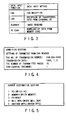
- FIGS. 4 to 6 are views showing examples of the setting contents of the identification conditions on the control panel 12.
- the setting contents of the identification conditions are displayed.
- the FAX number country number
- the output and storage destinations are set for the display contents shown in FIG. 5 (ST12).
- the output and storage destinations include a personal computer (a given personal computer is designated), a memory (a given memory is designated), printing-out (a given printer to print out data is designated), a mail box (a given mail box is designated), and another digital copying machine (a given digital copying machine is designated). Assume that the mail box is designated.
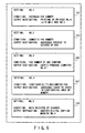
- a program instructing discharge to the mail box is set (ST14), and the set output destinations are displayed on confirmation contents 101 to 109 shown in FIG. 6 (ST16).
- identification conditions for identifying overseas FAX data must be set first.
- To identify overseas FAX data there is a method of designating the country number of Japan and identifying FAX data having a country number other than that of Japan as overseas FAX data. The method of setting the identification conditions has been described above, and a description thereof will be omitted.
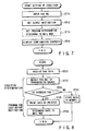
- the FAX number of the transmission source is detected (ST22). Whether the FAX data is an overseas FAX is checked on the basis of the detected FAX number (ST24). That is, it is checked whether the detected FAX number coincides with the country number of Japan. When the country number of the received FAX data does not coincide with the country number of Japan, the FAX data is determined as an overseas FAX (YES in ST24), and is output to the printer and printed (ST26). The printed FAX data is discharged to the mail box (ST28).
- This setting is setting No. 1 shown in FIG. 6, in which the condition is the overseas FAX number, and the output destination is the mail box No. 3 (67) to which data is discharged upon being printed out by the printer No. 4 (65).
- This setting is setting No. 2 shown in FIG. 6, in which the condition is the domestic FAX number, and the output destination is set to be, e.g., addresses 005000 to 007000 in the storage area of the HDD 35.
- the partner's FAX number is set as the identification condition of received data
- the output destination is set to the personal computer of this user
- data not corresponding to the identification condition is set to be stored in the HDD 35.
- the processing condition and output destination of received data are set on the control panel 12, as in case (1).
- This setting is setting No. 3 shown in FIG. 6, in which the condition is, e.g., the FAX number of ABC company, and the output destination is set to the personal computer No. 87 of the user who eagerly wants this FAX.
- the partner's FAX number is set as the identification number, and a given personal computer 61 of a user is designated as the output designation.
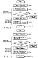
- the FAX number of the transmission source is detected (ST42). Whether the received FAX data is an emergency FAX is checked on the basis of the detected FAX number (ST44). That is, it is checked whether the detected FAX number coincides with the set FAX number. If YES, the FAX data is determined as an emergency FAX (YES in ST44), and transferred to the designated personal computer (ST46).
- a transfer end command is sent (ST48) to inform the user of completion of transfer of the FAX data.
- the FAX data is not an emergency FAX (NO in ST44), and the FAX data is stored in the HDD 35 (ST50). Note that detection of the FAX number of the transmission source, various determinations (data identification), command transmission, and the like are performed by the system CPU 31.
- a highly confidential document is not transmitted as a FAX document which will be seen by many people.
- the confidential document can be transmitted as a FAX document by designating confidentiality to the header data of FAX data and storing the confidentiality-designated FAX data in a memory managed by an ID code.
- the confidentiality is designated to the header data of FAX data to be transmitted.
- This confidentiality designation is set as the identification condition, and the output destination of the FAX data corresponding to this confidentiality designation is set to a memory managed by an ID code.
- Data not corresponding to the confidentiality designation is stored in the HDD 35.
- the identification condition and output destination of received data are set on the control panel 12, as in case (1).
- This setting is setting No. 4 shown in FIG. 6, in which the condition is a confidentially designated FAX, and the output destination is set to, e.g., addresses 04000 to 05000 in the confidentiality area of a memory.
- the confidentiality designation of the header data of received FAX data is set as the identification condition, and the page memory 23 managed by an ID code is set as the output destination.
- confidentiality designation is detected from the header data of the FAX data of the transmission source (ST62). If the confidentiality designation is detected, the received FAX data is determined as a confidentiality-designated document (YES in ST64) and stored in the page memory 23 managed by the ID code (ST66), and the header data of the FAX data is used as file data in storage (ST68). If confidentiality designation is not detected, the received FAX data is not determined as a confidentiality-designated document (NO in ST64), and stored in the HDD 35 where the data can be freely accessed (ST70). Note that detection of confidentiality designation data included in FAX data of the transmission source, various determinations (data identification), and the like are performed by the system CPU 31.
- received data can be distinguished for each interface. That is, data received by the FAX unit, data received by the scanner unit 13, and the like can be distinguished from each other, and their output destinations can be designated.
- This setting is setting No. 5 shown in FIG. 6, in which the condition is data set by the scanner 13, and the output destination is set to another digital data copying machine 63 connected to the LAN 41.
- data read by the scanner is also effective for data read by the scanner to set different transfer destinations in accordance with the data mode. That is, data read in the character mode can be set to be stored in an internal memory (e.g., an HDD) without performing compression processing, and data read in the photographic mode can be set to be stored in a page memory upon compression.
- data read in the character mode can be set to be stored in an internal memory (e.g., an HDD) without performing compression processing
- data read in the photographic mode can be set to be stored in a page memory upon compression.
- a data processing apparatus and a multifunction image forming apparatus which can distinguish, of received data, data (data file) which meet conditions set by the user in advance, from the remaining data.
- a specific FAX number is set as a condition, and FAX data corresponding to this condition is designated to be output to the user's personal computer.
- this FAX data is automatically transmitted to the user's personal computer.
- the user need not wait at the FAX unit (multifunction image forming apparatus in this case) until a FAX is received.
Landscapes
- Engineering & Computer Science (AREA)
- Multimedia (AREA)
- Signal Processing (AREA)
- General Engineering & Computer Science (AREA)
- Facsimiles In General (AREA)
- Accessory Devices And Overall Control Thereof (AREA)
- Facsimile Transmission Control (AREA)
Applications Claiming Priority (2)
| Application Number | Priority Date | Filing Date | Title |
|---|---|---|---|
| JP8053181A JPH09247411A (ja) | 1996-03-11 | 1996-03-11 | 情報処理システムおよび多機能画像形成装置 |
| JP53181/96 | 1996-03-11 |
Publications (1)
| Publication Number | Publication Date |
|---|---|
| EP0796001A2 true EP0796001A2 (de) | 1997-09-17 |
Family
ID=12935708
Family Applications (1)
| Application Number | Title | Priority Date | Filing Date |
|---|---|---|---|
| EP97301363A Withdrawn EP0796001A2 (de) | 1996-03-11 | 1997-02-28 | Datenverarbeitungsgerät, das einen Übertragungsempfänger für Bilddaten bestimmt |
Country Status (3)
| Country | Link |
|---|---|
| EP (1) | EP0796001A2 (de) |
| JP (1) | JPH09247411A (de) |
| CN (1) | CN1166009A (de) |
Cited By (3)
| Publication number | Priority date | Publication date | Assignee | Title |
|---|---|---|---|---|
| US6456400B1 (en) * | 1994-04-18 | 2002-09-24 | Canon Kabushiki Kaisha | Data communication apparatus, method and system |
| EP0977113A3 (de) * | 1998-07-31 | 2005-06-08 | Canon Kabushiki Kaisha | Zentraler Server, Informationsverarbeitungsgerät und Verfahren sowie Drucksystem |
| US7619764B2 (en) | 1998-07-31 | 2009-11-17 | Canon Kabushiki Kaisha | Center server, information processing apparatus and method, and print system |
Families Citing this family (3)
| Publication number | Priority date | Publication date | Assignee | Title |
|---|---|---|---|---|
| JP4511264B2 (ja) * | 2004-07-02 | 2010-07-28 | 株式会社東芝 | 画像形成装置及びその画像形成装置の情報出力方法 |
| JP2006067116A (ja) * | 2004-08-25 | 2006-03-09 | Canon Inc | 情報処理システムのデータ処理方法、情報処理システム、記憶媒体、プログラム |
| JP2019057196A (ja) * | 2017-09-22 | 2019-04-11 | 横河電機株式会社 | 情報収集装置、情報収集方法 |
-
1996
- 1996-03-11 JP JP8053181A patent/JPH09247411A/ja active Pending
-
1997
- 1997-02-28 EP EP97301363A patent/EP0796001A2/de not_active Withdrawn
- 1997-03-11 CN CN 97102949 patent/CN1166009A/zh active Pending
Cited By (3)
| Publication number | Priority date | Publication date | Assignee | Title |
|---|---|---|---|---|
| US6456400B1 (en) * | 1994-04-18 | 2002-09-24 | Canon Kabushiki Kaisha | Data communication apparatus, method and system |
| EP0977113A3 (de) * | 1998-07-31 | 2005-06-08 | Canon Kabushiki Kaisha | Zentraler Server, Informationsverarbeitungsgerät und Verfahren sowie Drucksystem |
| US7619764B2 (en) | 1998-07-31 | 2009-11-17 | Canon Kabushiki Kaisha | Center server, information processing apparatus and method, and print system |
Also Published As
| Publication number | Publication date |
|---|---|
| JPH09247411A (ja) | 1997-09-19 |
| CN1166009A (zh) | 1997-11-26 |
Similar Documents
| Publication | Publication Date | Title |
|---|---|---|
| US5673373A (en) | Image forming system with security function | |
| US6437875B1 (en) | Method of processing data in various applications | |
| US6931432B1 (en) | Data transmission apparatus and method with control feature for transmitting data or transmitting a storage location of data | |
| US7414748B2 (en) | Image input/output apparatus, method of controlling image input/output apparatus, image input/output system, and storage media | |
| US8477352B2 (en) | Image forming apparatus, control method thereof, image forming system, and program | |
| JP3486452B2 (ja) | 複合画像処理装置 | |
| JP2001027986A (ja) | データ処理装置及び処理部選択方法 | |
| JPH1083263A (ja) | 画像形成装置及び画像処理方法 | |
| US6229620B1 (en) | Image processing apparatus and method thereof | |
| EP1265431B1 (de) | Bildübertragungsverfahren und -Vorrichtung | |
| JPH07264372A (ja) | 画像形成記憶装置 | |
| JP2007067849A (ja) | 画像アーカイブシステム | |
| EP0796001A2 (de) | Datenverarbeitungsgerät, das einen Übertragungsempfänger für Bilddaten bestimmt | |
| JP2000358144A (ja) | 画像入出力システム及びその制御方法 | |
| JP2000151873A (ja) | 情報処理システム及び情報処理方法 | |
| JP4077958B2 (ja) | データ処理装置、方法及びプログラムを格納した記憶媒体 | |
| JP3490670B2 (ja) | 画像処理方法、画像処理装置及び画像処理システム | |
| JP2004186810A (ja) | 画像形成方法 | |
| JP2003337681A (ja) | 画像処理システム及びサーバ装置 | |
| JP2001339561A (ja) | 複合画像処理装置及びネットワーク複写におけるリカバリー方法 | |
| JPH07264385A (ja) | 画像形成記憶装置 | |
| JPH11327376A (ja) | リモートコピーシステムおよびリモートコピー方法 | |
| JPH11149358A (ja) | 画像入出力制御装置、画像入出力システム、最適用紙サイズ印刷方法および記憶媒体 | |
| JP3202477B2 (ja) | 情報処理方法及び装置 | |
| JP3686413B2 (ja) | ネットワークプリントシステムとネットワークプリント方法 |
Legal Events
| Date | Code | Title | Description |
|---|---|---|---|
| PUAI | Public reference made under article 153(3) epc to a published international application that has entered the european phase |
Free format text: ORIGINAL CODE: 0009012 |
|
| 17P | Request for examination filed |
Effective date: 19970324 |
|
| AK | Designated contracting states |
Kind code of ref document: A2 Designated state(s): DE FR GB |
|
| STAA | Information on the status of an ep patent application or granted ep patent |
Free format text: STATUS: THE APPLICATION HAS BEEN WITHDRAWN |
|
| 18W | Application withdrawn |
Withdrawal date: 19980402 |