EP0796033A1 - Telefon mit elektromechanischem Wandler, Verfahren zur Adaption der Wandlersfrequenzwiedergabe und Verfahren zur Melodiekodierung - Google Patents
Telefon mit elektromechanischem Wandler, Verfahren zur Adaption der Wandlersfrequenzwiedergabe und Verfahren zur Melodiekodierung Download PDFInfo
- Publication number
- EP0796033A1 EP0796033A1 EP97200666A EP97200666A EP0796033A1 EP 0796033 A1 EP0796033 A1 EP 0796033A1 EP 97200666 A EP97200666 A EP 97200666A EP 97200666 A EP97200666 A EP 97200666A EP 0796033 A1 EP0796033 A1 EP 0796033A1
- Authority
- EP
- European Patent Office
- Prior art keywords
- transducer
- melody
- repetitions
- telephone equipment
- note
- Prior art date
- Legal status (The legal status is an assumption and is not a legal conclusion. Google has not performed a legal analysis and makes no representation as to the accuracy of the status listed.)
- Withdrawn
Links
Images


Classifications
-
- H—ELECTRICITY
- H04—ELECTRIC COMMUNICATION TECHNIQUE
- H04M—TELEPHONIC COMMUNICATION
- H04M19/00—Current supply arrangements for telephone systems
- H04M19/02—Current supply arrangements for telephone systems providing ringing current or supervisory tones, e.g. dialling tone or busy tone
- H04M19/04—Current supply arrangements for telephone systems providing ringing current or supervisory tones, e.g. dialling tone or busy tone the ringing-current being generated at the substations
-
- H—ELECTRICITY
- H04—ELECTRIC COMMUNICATION TECHNIQUE
- H04R—LOUDSPEAKERS, MICROPHONES, GRAMOPHONE PICK-UPS OR LIKE ACOUSTIC ELECTROMECHANICAL TRANSDUCERS; ELECTRIC HEARING AIDS; PUBLIC ADDRESS SYSTEMS
- H04R3/00—Circuits for transducers
Definitions
- the present invention relates to telephone equipment provided with a controllable electro-mechanical transducer which delivers a variable sound level as a function of frequency, as well as a method for playing melodies on such equipment, and a method for coding such equipment. melodies.
- Telephone equipment and in particular mobile telephones, must emit rings which can be heard in a noisy environment.
- these devices are subject to severe constraints in terms of space (weight, volume) and supply voltage.
- electro-mechanical transducers or sound vibrators
- FIG. 2 the frequency response of such an electro-mechanical transducer is shown in FIG. 2. This frequency response is very irregular, but a noise level of approximately 95 dB is obtained for a frequency of 2.730 kHz.
- a first object of the present invention is to manage to play melodies composed of a wide variety of notes with the electro-mechanical transducers described in the preceding paragraphs which commonly equip telephone equipment.
- telephone equipment according to the invention and as defined in the introductory paragraph is characterized in that it comprises means for adapting the frequency response of said transducer to obtain a constant sound level whatever the frequency considered.
- the invention is particularly applicable in the field of mobile telephones.
- said adaptation means consist notably in varying the duty cycle of the excitation signal of said electro-mechanical transducer.
- the telephone equipment then advantageously comprises storage means for storing for each frequency at least one value of the duty cycle of said excitation signal to obtain at least one sound level given at the output of the transducer.
- Another object of the present invention is to provide an efficient method for coding such a melody.
- Such a melody coding method can be implemented independently of the method described above for playing melodies with the electro-mechanical transducers which are currently fitted on commercial telephones.
- FIG. 1 there is shown a telephone equipment according to the invention.
- Such equipment includes in particular an antenna 1, a loudspeaker / listener 2, a screen 3, a keyboard 4 a microphone 5, an electro-mechanical transducer 6 which is connected to an output 7 of a microprocessor assembly 8.
- the microprocessor assembly 8 is a 91CL301 microprocessor manufactured by PHILIPS (made from a Motorola 68000).
- the electro-mechanical transducer is an SBT 0905 RP transducer manufactured by SAMBU.
- the electro-mechanical transducer 6 is composed of a coil mounted around an air gap. A metal membrane is located above the electromagnet thus formed. An excitation signal I (current) applied to the transducer varies the magnetic field near the membrane, thus causing it to oscillate at the frequency of said signal.
- the use of slot excitation signals allows maximum variation of the magnetic field to be obtained.
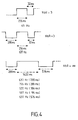
- the excitation signal I has been represented. Its duty cycle R is equal to A / A + B where A is the duration of the high front and B that of the low front. The generation of these signals in slots is ensured by the microprocessor assembly 8.
- the sound level of the output of the transducer (expressed in decibels) is represented as a function of the frequency of the excitation signal of the transducer, in free field (that is to say outside the shell) under normal conditions. of operation (especially when the duty cycle of the excitation signal is 50%). For frequencies between 500Hz and 10kHz, the output sound level varies from 50dB to 95dB. Such transducers therefore do not allow melodies composed of a plurality of notes of different frequencies to be played.
- the invention consists in adapting the response of the transducer as a function of the frequency that one seeks to play in order to obtain a constant sound level.
- the invention therefore consists in associating with each frequency a value of the duty cycle of the excitation signal of the transducer of between 1% and 8% to obtain a given sound level.
- excitation signals of variable frequency and duty cycle
- the frequencies which can be generated depend on the clock (F CLK ) which controls the microprocessor: one cannot therefore obtain only a certain number of discrete values, and not a continuous variation of the frequency.
- F CLK clock which controls the microprocessor: one cannot therefore obtain only a certain number of discrete values, and not a continuous variation of the frequency.
- a range has been selected allowing music tracks to be played. The level of this range was chosen to obtain satisfactory listening comfort, and within this range we retained the frequencies which were sufficiently close to the musical notes.
- each note is referenced by a digit in hexadecimal (4 to D in order of increasing frequencies, in the example described).
- a T1 table gives, for each note, the reference / frequency correspondence.
- At least some of these elements are defined inside a window W of a determined duration.
- a time delay corresponding to said duration is started before playing the elements included in this window. And the content of the window is played until this timeout has expired.
- table T3 can be coded in hexadecimal on 4 digits.
- the first digit indicates whether it is a silence (0), a note (4 to D), a repetition (E) or a window (1).
- the following three digits indicate the duration of the note or of the rest.
- the following two digits indicate the number of repetitions and the last digit indicates the number of rows to repeat in the table.
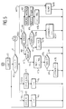
- the processor 8 sequentially reads the table T3. For this, in box K1, an index i is initialized at the address adr (M) of the melody M in the table T3. Then in box K2, a test is performed on the value of the first digit of line i of table T3 (in FIG. 5, this digit is denoted d1). If this digit indicates a note N to be played, the operation continues in box K3. If it indicates a silence S, it continues in box K5, if it indicates a repetition R, it continues in box K7, and if it indicates a window, it continues in box K19. Finally, if this field indicates that the melody is finished (F), operation ends in box K20.
- the variables indicating the characteristics of the excitation signal I to be sent to the transducer 6 are initialized (frequency F, duration D, duty cycle R).
- the frequency F is read in the table T1 from the reference of the note N to be played.
- the duration during which the signal must be transmitted is read from table T3 directly.
- the value of its duty cycle is read in table T2 from the desired sound level V, and from the note N to play.
- the excitation signal I (F, D, R) is sent to the transducer 6, then in box K4, the index i is incremented by one, and operation resumes in box K2.
- Box K5 deals with the case of rests.
- the duration D during which the silence must be respected is given directly by the table T3.
- An excitation signal I (F, D, R) of zero frequency and duty cycle is sent to the transducer 6.
- the index i is incremented by one and operation resumes in box K2 .
- box K8 the characteristics (NbR, NbL) of this new repetition are stored in the stack. Then in box K9, if the variable NbR has a finite value, it is decremented by one. In box K10, the number i is subtracted from the index i NbL, then operation resumes in box K2.
- box K12 it is checked whether the variable NbR has a finite value. In this case the operation continues in box K13. Otherwise it continues to box K16. In box K13 the variable NbR is decremented by one, and the number NbL is subtracted from the index i. Then in box K14 we test if NbR is equal to zero. In this case, the corresponding line in the stack is released (which is symbolized in box K15 by decreasing by one unit the current index j (STACK) of the stack STACK), before resuming operation in box K2 . Otherwise, operation resumes directly in box K2.
- STACK current index j
- box K16 it is checked whether one is inside a window whose time delay (TEMP) has expired. In this case (box K17), the line corresponding to the repetition in the stack is released, then the index i is incremented before resuming operation in box K2. Otherwise (box K18), subtract from the index i the number NbL before resuming operation in box K2.
- TCP time delay
Landscapes
- Engineering & Computer Science (AREA)
- Signal Processing (AREA)
- Physics & Mathematics (AREA)
- Acoustics & Sound (AREA)
- Electrophonic Musical Instruments (AREA)
- Telephone Function (AREA)
Applications Claiming Priority (2)
| Application Number | Priority Date | Filing Date | Title |
|---|---|---|---|
| FR9603155 | 1996-03-13 | ||
| FR9603155A FR2746240A1 (fr) | 1996-03-13 | 1996-03-13 | Telephone equipe d'un transducteur electro-mecanique, procede d'adaptation de la reponse en frequence d'un tel transducteur et procede de codage d'une melodie |
Publications (1)
| Publication Number | Publication Date |
|---|---|
| EP0796033A1 true EP0796033A1 (de) | 1997-09-17 |
Family
ID=9490146
Family Applications (1)
| Application Number | Title | Priority Date | Filing Date |
|---|---|---|---|
| EP97200666A Withdrawn EP0796033A1 (de) | 1996-03-13 | 1997-03-06 | Telefon mit elektromechanischem Wandler, Verfahren zur Adaption der Wandlersfrequenzwiedergabe und Verfahren zur Melodiekodierung |
Country Status (6)
| Country | Link |
|---|---|
| US (1) | US5953408A (de) |
| EP (1) | EP0796033A1 (de) |
| JP (1) | JPH1013498A (de) |
| KR (1) | KR970068399A (de) |
| CN (1) | CN1169076A (de) |
| FR (1) | FR2746240A1 (de) |
Families Citing this family (11)
| Publication number | Priority date | Publication date | Assignee | Title |
|---|---|---|---|---|
| JPH11220518A (ja) * | 1998-01-30 | 1999-08-10 | Matsushita Electric Ind Co Ltd | 携帯電話機 |
| US6215391B1 (en) * | 1999-10-22 | 2001-04-10 | Ericsson Inc. | Variable frequency buzzer assembly |
| KR100395198B1 (ko) * | 1999-10-29 | 2003-08-21 | 가부시키가이샤 히타치세이사쿠쇼 | 셀룰러 전화기 |
| US7149509B2 (en) | 1999-12-06 | 2006-12-12 | Twenty Year Innovations, Inc. | Methods and apparatuses for programming user-defined information into electronic devices |
| US6496692B1 (en) * | 1999-12-06 | 2002-12-17 | Michael E. Shanahan | Methods and apparatuses for programming user-defined information into electronic devices |
| US8170538B2 (en) | 1999-12-06 | 2012-05-01 | Solocron Media, Llc | Methods and apparatuses for programming user-defined information into electronic devices |
| KR100437759B1 (ko) * | 2000-02-24 | 2004-06-26 | 엘지전자 주식회사 | 이동 통신 단말기의 듀얼 톤 다중 주파수 발생기를 이용한벨소리 재생 방법 |
| GB0004538D0 (en) * | 2000-02-25 | 2000-04-19 | Koninkl Philips Electronics Nv | Method of transferring melodic information to a terminal |
| US20020103552A1 (en) * | 2000-12-04 | 2002-08-01 | Mike Boucher | Method and apparatus to reduce processing requirements for the playback of complex audio sequences |
| KR100460107B1 (ko) * | 2000-12-26 | 2004-12-03 | 엘지전자 주식회사 | 무선 단말기에서 벨소리로 표현 가능한 주파수 출력 제어방법 |
| FR2822621A1 (fr) * | 2001-03-21 | 2002-09-27 | Cit Alcatel | Procede de codage de melodie ainsi qu'un terminal mobile permettant de mettre en oeuvre ce procede |
Citations (6)
| Publication number | Priority date | Publication date | Assignee | Title |
|---|---|---|---|---|
| GB2091470A (en) * | 1980-12-24 | 1982-07-28 | Casio Computer Co Ltd | Electronic Musical Instrument |
| EP0094162A2 (de) * | 1982-05-10 | 1983-11-16 | Northern Telecom Limited | Verfahren zur Erzeugung von Spannungssignalen mit einer Gleichspannungskomponente und einem grossen Dynamikbereich |
| US4598179A (en) * | 1984-06-28 | 1986-07-01 | Sakura Telecommunications, Inc. | Telephone privacy system |
| US4699518A (en) * | 1985-09-12 | 1987-10-13 | Rhythm Watch Company Limited | Musical scale generating circuit |
| US4731828A (en) * | 1985-06-07 | 1988-03-15 | Plessey Overseas Limited | Ring trip detection in telecommunications exchanges |
| JPH03127522A (ja) * | 1989-10-13 | 1991-05-30 | Toshiba Corp | 鳴音発生回路及びこの回路を使用した小形無線機並びに選択呼出受信機 |
Family Cites Families (1)
| Publication number | Priority date | Publication date | Assignee | Title |
|---|---|---|---|---|
| US4866766A (en) * | 1988-09-06 | 1989-09-12 | Motorola, Inc. | Telephone device having customized ring capability |
-
1996
- 1996-03-13 FR FR9603155A patent/FR2746240A1/fr active Pending
-
1997
- 1997-03-06 EP EP97200666A patent/EP0796033A1/de not_active Withdrawn
- 1997-03-06 US US08/812,188 patent/US5953408A/en not_active Expired - Fee Related
- 1997-03-11 JP JP9056226A patent/JPH1013498A/ja active Pending
- 1997-03-13 CN CN97110933.8A patent/CN1169076A/zh active Pending
- 1997-03-13 KR KR1019970009134A patent/KR970068399A/ko not_active Ceased
Patent Citations (6)
| Publication number | Priority date | Publication date | Assignee | Title |
|---|---|---|---|---|
| GB2091470A (en) * | 1980-12-24 | 1982-07-28 | Casio Computer Co Ltd | Electronic Musical Instrument |
| EP0094162A2 (de) * | 1982-05-10 | 1983-11-16 | Northern Telecom Limited | Verfahren zur Erzeugung von Spannungssignalen mit einer Gleichspannungskomponente und einem grossen Dynamikbereich |
| US4598179A (en) * | 1984-06-28 | 1986-07-01 | Sakura Telecommunications, Inc. | Telephone privacy system |
| US4731828A (en) * | 1985-06-07 | 1988-03-15 | Plessey Overseas Limited | Ring trip detection in telecommunications exchanges |
| US4699518A (en) * | 1985-09-12 | 1987-10-13 | Rhythm Watch Company Limited | Musical scale generating circuit |
| JPH03127522A (ja) * | 1989-10-13 | 1991-05-30 | Toshiba Corp | 鳴音発生回路及びこの回路を使用した小形無線機並びに選択呼出受信機 |
Non-Patent Citations (1)
| Title |
|---|
| PATENT ABSTRACTS OF JAPAN vol. 15, no. 334 (E - 1104) 26 August 1991 (1991-08-26) * |
Also Published As
| Publication number | Publication date |
|---|---|
| KR970068399A (ko) | 1997-10-13 |
| US5953408A (en) | 1999-09-14 |
| CN1169076A (zh) | 1997-12-31 |
| FR2746240A1 (fr) | 1997-09-19 |
| JPH1013498A (ja) | 1998-01-16 |
Similar Documents
| Publication | Publication Date | Title |
|---|---|---|
| US6816599B2 (en) | Ear level device for synthesizing music | |
| CA2337176C (fr) | Procede d'ajustement du volume sonore d'un enregistrement sonore numerique | |
| EP0796033A1 (de) | Telefon mit elektromechanischem Wandler, Verfahren zur Adaption der Wandlersfrequenzwiedergabe und Verfahren zur Melodiekodierung | |
| FR2475390A1 (fr) | Appareil pour conditionnner l'ouie d'un patient | |
| EP1593116B1 (de) | Verfahren zur differenzierten digitalen Sprach- und Musikbearbeitung, Rauschfilterung, Erzeugung von Spezialeffekten und Einrichtung zum Ausführen des Verfahrens | |
| AU2002219093A1 (en) | Binaural hearing system and method of synthesizing music | |
| US20140086426A1 (en) | Masking sound generation device, masking sound output device, and masking sound generation program | |
| FR2466811A1 (fr) | Systeme pour donner, sous une forme vocale, dans un vehicule automobile des informations relatives au parcours | |
| EP1606799B1 (de) | Verfahren und Vorrichtung zur Erzeugung einer Tonfolge | |
| EP0041009A1 (de) | Elektronisches Metronom | |
| EP0052544A1 (de) | Klangreglerschaltung | |
| US7197149B1 (en) | Cellular phone | |
| EP1161076A1 (de) | Tragbares Funktelefon mit verbessertem Rufsignal | |
| CH558119A (de) | Enceinte munie de haut-parleurs. | |
| FR2706657A1 (fr) | Dispositif de défiltrage audio-progressif. | |
| EP1148700B1 (de) | Atemgeräuschfreies Mobiltelefon | |
| Maher | Fundamentals of Audio Signals and Systems | |
| FR2733845A1 (fr) | Metronome vocal | |
| EP0757913A2 (de) | Generator zur Erzeugung von elektromagnetischen Wellen | |
| WO1998007130A1 (fr) | Procede et dispositif pour l'enseignement des langues | |
| FR2636856A1 (fr) | Dispositif electronique autonome ludique et/ou pedagogique | |
| FR3093856A1 (fr) | Dispositif de modification audio d’un signal d’entrée audio, et procédé correspondant | |
| FR2840759A1 (fr) | Procede de sonorisation | |
| EP0066515A1 (de) | Gerät zur Schallerzeugung und Vorrichtung zur Kontrolle der Schallisolierung in Gebäuden | |
| Chasin | Inexpensive environmental modifications |
Legal Events
| Date | Code | Title | Description |
|---|---|---|---|
| PUAI | Public reference made under article 153(3) epc to a published international application that has entered the european phase |
Free format text: ORIGINAL CODE: 0009012 |
|
| AK | Designated contracting states |
Kind code of ref document: A1 Designated state(s): CH DE FR GB LI |
|
| 17P | Request for examination filed |
Effective date: 19980317 |
|
| RAP3 | Party data changed (applicant data changed or rights of an application transferred) |
Owner name: KONINKLIJKE PHILIPS ELECTRONICS N.V. |
|
| STAA | Information on the status of an ep patent application or granted ep patent |
Free format text: STATUS: THE APPLICATION HAS BEEN WITHDRAWN |
|
| 18W | Application withdrawn |
Withdrawal date: 20000814 |