EP0796155B1 - Matrice d'emboutissage ajustable - Google Patents
Matrice d'emboutissage ajustable Download PDFInfo
- Publication number
- EP0796155B1 EP0796155B1 EP95940852A EP95940852A EP0796155B1 EP 0796155 B1 EP0796155 B1 EP 0796155B1 EP 95940852 A EP95940852 A EP 95940852A EP 95940852 A EP95940852 A EP 95940852A EP 0796155 B1 EP0796155 B1 EP 0796155B1
- Authority
- EP
- European Patent Office
- Prior art keywords
- pin
- pin means
- drive shaft
- self
- drive
- Prior art date
- Legal status (The legal status is an assumption and is not a legal conclusion. Google has not performed a legal analysis and makes no representation as to the accuracy of the status listed.)
- Expired - Lifetime
Links
- 239000011159 matrix material Substances 0.000 claims description 18
- 230000002441 reversible effect Effects 0.000 claims description 15
- 238000000034 method Methods 0.000 claims description 12
- 238000013500 data storage Methods 0.000 claims description 11
- 230000004044 response Effects 0.000 claims description 4
- 230000003213 activating effect Effects 0.000 claims description 2
- 239000002184 metal Substances 0.000 description 8
- 238000004519 manufacturing process Methods 0.000 description 5
- 239000000463 material Substances 0.000 description 5
- 238000003860 storage Methods 0.000 description 5
- 230000008859 change Effects 0.000 description 4
- 238000013519 translation Methods 0.000 description 4
- 238000013461 design Methods 0.000 description 3
- 238000010586 diagram Methods 0.000 description 3
- 230000008569 process Effects 0.000 description 3
- 238000012546 transfer Methods 0.000 description 3
- 229910000831 Steel Inorganic materials 0.000 description 2
- 230000004913 activation Effects 0.000 description 2
- 239000007787 solid Substances 0.000 description 2
- 239000010959 steel Substances 0.000 description 2
- 238000012360 testing method Methods 0.000 description 2
- XBWAZCLHZCFCGK-UHFFFAOYSA-N 7-chloro-1-methyl-5-phenyl-3,4-dihydro-2h-1,4-benzodiazepin-1-ium;chloride Chemical compound [Cl-].C12=CC(Cl)=CC=C2[NH+](C)CCN=C1C1=CC=CC=C1 XBWAZCLHZCFCGK-UHFFFAOYSA-N 0.000 description 1
- 229920001875 Ebonite Polymers 0.000 description 1
- 229910001315 Tool steel Inorganic materials 0.000 description 1
- 238000009825 accumulation Methods 0.000 description 1
- 238000004891 communication Methods 0.000 description 1
- 238000012937 correction Methods 0.000 description 1
- 238000006073 displacement reaction Methods 0.000 description 1
- 230000000694 effects Effects 0.000 description 1
- 239000013536 elastomeric material Substances 0.000 description 1
- -1 for instance Substances 0.000 description 1
- 230000006870 function Effects 0.000 description 1
- 238000012423 maintenance Methods 0.000 description 1
- 230000007246 mechanism Effects 0.000 description 1
- 230000005055 memory storage Effects 0.000 description 1
- 230000003287 optical effect Effects 0.000 description 1
- 239000004810 polytetrafluoroethylene Substances 0.000 description 1
- 229920001343 polytetrafluoroethylene Polymers 0.000 description 1
- 238000003825 pressing Methods 0.000 description 1
- 230000008439 repair process Effects 0.000 description 1
- 230000000717 retained effect Effects 0.000 description 1
Images



Classifications
-
- B—PERFORMING OPERATIONS; TRANSPORTING
- B30—PRESSES
- B30B—PRESSES IN GENERAL
- B30B15/00—Details of, or accessories for, presses; Auxiliary measures in connection with pressing
- B30B15/02—Dies; Inserts therefor; Mounting thereof; Moulds
-
- B—PERFORMING OPERATIONS; TRANSPORTING
- B21—MECHANICAL METAL-WORKING WITHOUT ESSENTIALLY REMOVING MATERIAL; PUNCHING METAL
- B21D—WORKING OR PROCESSING OF SHEET METAL OR METAL TUBES, RODS OR PROFILES WITHOUT ESSENTIALLY REMOVING MATERIAL; PUNCHING METAL
- B21D37/00—Tools as parts of machines covered by this subclass
- B21D37/02—Die constructions enabling assembly of the die parts in different ways
-
- B—PERFORMING OPERATIONS; TRANSPORTING
- B21—MECHANICAL METAL-WORKING WITHOUT ESSENTIALLY REMOVING MATERIAL; PUNCHING METAL
- B21J—FORGING; HAMMERING; PRESSING METAL; RIVETING; FORGE FURNACES
- B21J13/00—Details of machines for forging, pressing, or hammering
- B21J13/02—Dies or mountings therefor
-
- B—PERFORMING OPERATIONS; TRANSPORTING
- B30—PRESSES
- B30B—PRESSES IN GENERAL
- B30B7/00—Presses characterised by a particular arrangement of the pressing members
-
- G—PHYSICS
- G05—CONTROLLING; REGULATING
- G05B—CONTROL OR REGULATING SYSTEMS IN GENERAL; FUNCTIONAL ELEMENTS OF SUCH SYSTEMS; MONITORING OR TESTING ARRANGEMENTS FOR SUCH SYSTEMS OR ELEMENTS
- G05B2219/00—Program-control systems
- G05B2219/30—Nc systems
- G05B2219/49—Nc machine tool, till multiple
- G05B2219/49025—By positioning plurality of rods, pins to form together a mold, maquette
Definitions
- the present invention relates to a self-adjusting die for forming a three-dimensional contoured die surface, comprising a plurality of individual pin means defining a matrix of pin rows and pin columns, each said pin means being independently movable in an extended and retracted position along a single axis; control means for generating desired positional information for each of said plurality of individual pin means of said matrix; and drive means having a drive motor for driving at least one first drive shaft for driving at least one of each said row/column of said pin means.
- a typical application of the die is to form a computer-controlled three dimensional surface, suitable for forming sheet metal products and the like.
- the usual tooling process begins once the sheet metal product contours have been described and are finalized.
- the typical process requires the manufacture of a contoured form die, followed by a testing phase (often known as tool "prove-out") to assure that the form die imparts the proper contour to the sheet metal product. Should changes to the contour of the die be required (for example, to make springback adjustments) then rework of the existing die or re-manufacture of a new die becomes necessary in order to achieve the appropriate contour changes.
- predesigned and specifically designed form dies are utilized to achieve contoured surfaces for sheet metal product and the like.
- Manufacturers usually maintain and store sets of specifically designed form dies and, depending upon the application, will retrieve the appropriate die depending upon the surface contour desired to be achieved. This is not a cost-effective method since a new form die has to be manufactured for each new application, not to mention the attendant costs of testing and storing the new form die.
- a self-adjusting die as defined above, wherein torque engaging means corresponding to and operatively connected with each said pin means are provided, each said torque engaging means selectively engaging said or one of said first drive shafts to selectively supply torque to said corresponding pin means, said drive means and said torque engaging means being responsive to said positional information generated by said control means for providing simultaneous and independent axial movement of each said pin means of said matrix along each respective said single axis.
- the die may be in the form of a self-adjusting form die that is computer controlled for imparting proper contours to a sheet metal product.
- An adjustable form die can be provided that permits virtually instant contour changes to the forming tool by computer control without the need to manufacture templates, molds, and without having to remove the die from the metal forming press when changing surface contours.
- the die to be described in detail is an adjustable form die that obviates the need for a manufacturing facility to fabricate, store, and retrieve specially designed forming dies for each contour surface application. It can also reduce the costs of individual form die production, inventory, and storage, by allowing rapid prototyping and rapid "tweaking" of finished parts during tool prove-out process.
- an adjustable form die that is capable of changing its contour in real time when real time shape adjustments are required.
- the adjustable form die may include a computer means having memory and for contour storage and retrieval and an adjustable form die that includes a multi-pin design with feedback controlled multi-motor pin positioning.
- a method for forming a tool die having a plurality of pin means arranged in a matrix comprising a plurality of rows/columns said die including drive means having a drive motor for each row/column of said matrix of pins for rotating a first drive shaft, and torque engaging means corresponding to and operatively connected with each said pin means, for selectively engaging said drive means to selectively supply torque to said corresponding pin means, said drive means and torque engaging means for independently driving each individual pin means of said plurality to a desired position along a single axis, said method comprising the steps of:
- the form die apparatus 10 comprises a frame 13 for housing several rows 12a and columns 12b of adjacently positioned pins 15.
- each pin is a hollow square, approximately one inch in width and is spaced apart from each adjacent pin at a distance of one inch (center to center).
- pins 15 may be solid and even cylindrical in shape and having a one inch diameter. It is understood that the pin spacing distance is merely a design choice depending upon the configuration and thickness of the pins.
- adjacently located pins must be placed at a distance from each other sufficient to accommodate the movement of various mechanical components such as the electric drive motors 50 for adjusting the vertical translation of each pin as shown generally in Figure 1.
- pins, plates, and frame materials described hereinbelow are formed of heavy steel to assure that the die is rugged and will maintain maximum tool rigidity. Only the minimum amount of material is removed from the heavy steel die plates 77, 87, 30 and 35 ( Figure 3) so that maximum tool rigidity is retained. These plates are built up progressively so that disassembly for maintenance or repair is facilitated. Pin faces are spherically ground from hardened tool steel and made removable for easy replacement. Additionally, all parts may be specially coated with materials, for instance, PTFE, to minimize friction. As shown in Figure 2, a hard rubber (or other elastomeric material) material 16 is placed on top of the pins 15 to protect the formed parts and ensure that bumps from the individual pin heads are not transmitted to the sheet metal product.
- each of the pins 15 are hollow and square-shaped, so that they are unable to rotate within the form die frame 13.
- each of the pins may be solid and/or shaped in a variety of ways that are largely determined by the types and thicknesses of material that are to be formed in a particular pressing application.
- the pins 15 are permanently attached or welded to nuts 26 at the pin end 15a, and are drilled so that the inside diameter of the pin 15 closely fits the outside diameter of the rotating threaded shaft 25.
- the hollow pin 15 may alternately be of a one-piece semi-or fully threaded configuration for extending or retracting movement along rotating threaded shaft 25.
- the threaded pins 15 are each supported within frame 13 which reacts the pin side loads.
- the axial pins 15 loads are reacted by thrust bearings 28 which transfer axial loads when the pins are extending or retracting along their respective vertical axes to the forming machine's bed or platten.
- each threaded shaft 25 is connected to the output side of an electric clutch 60.
- the electric clutch 60 when actuated, engages torque from a drive shaft 56 to rotate each pin's threaded shaft 25.
- torque from the drive shaft 56 will be disengaged from the pin's threaded shaft 25 and rotation of that shaft will terminate.
- a spur or pinion gear 65 located at the end of each drive shaft 56 assures constant torque to the drive shaft as long as it's respective motor (not shown) is turning.
- the spur or pinion gear 65 receives its torque via a worm gear 55a from a rotating worm gear shaft 55 which is provided for each row (or column) of pins and mounted at right angles to a row (or column) of pinion gears 65 and directly connected to an electric motor 50.
- Each worm gear shaft 55 has a plurality of worm gears, such as worm gear 55a shown in Figure 3, that are spaced one inch apart (center to center distance) along the shaft 55 and associated with a respective pin 15 for engaging a respective right angle pinion gear 65.
- each worm gear shaft 55, drive shaft 56, pinion gear 65, and electric clutch 60 are housed in gear drive plate 87.
- Each worm gear shaft 55 is appropriately supported within the gear drive plate 87 by capped precision bearings 88 that are strategically placed at each drive shaft location to assure proper alignment, smooth operation, and long life.
- the capped bearings are fastened to the gear drive plate by fasteners 89.
- a rotary optical encoder 75 is mounted within encoder housing plate 77 and provided for each pin 15 to provide positional feedback information for the control system 100 as will be explained in greater detail below.
- a power-off brake 85 associated with each pin is also provided within frame 13 for ensuring additional stability to the pin.
- the clutch 60 and power-off brake 85 are simultaneously controlled by control system 100 utilizing positional feedback information generated by rotary encoder 75; the brake being turned off when the clutch is engaging the threaded screw shaft 25 to enable axial movement of said pin.
- an electric motor 50 drives a worm gear shaft 55 that has worm gear tap-off points at each pin location along its length.
- the motor is preferably bi-directional in that it could be powered to drive the worm gear shaft 55 in both forward and reverse directions; the forward direction when increasing vertical movement of the pin relative to a predetermined set of "home" position is desired, and, reverse direction when pin positioning needs to be tweaked or altered to allow for springback adjustments.
- a suitable motor controller 114 and motor power device 116 is provided for each motor 50; the motor controller 114 receiving instructions from the computer controller 99 via line 112 for directional and speed information.
- the worm gear shaft 55 driven by each motor is long and can power a complete line of pins in a row/column.
- each pin occupies 1 square inch of space
- a form die that is four feet by six feet is configured with 48 pins in a line, and 72 lines yielding 3456 pins total.
- a worm gear shaft 55 could conceivably power either the 48 pin line or the 72 pin line depending upon motor torque considerations and cost.
- the motors 50 are stagger mounted on opposite sides of the frame to allow sufficient side clearance space for the motor housings. The concept is applicable to any number of pins per line and any number of lines.
- each reversible motor 50 is linked directly to each pinion drive shaft 56 so that all the worm gears on each individual shaft turn together when it's respective motor is activated.
- the computer control system 100 sorts through the positional data that has been previously input, simultaneously enables each motor to drive its respective worm gear shaft and pins, and then individually addresses each "power-off" brake 85 and clutch unit 60 in the manner described below.
- the computer activates the appropriate brake/clutch unit to allow translational movement of its respective pin until the rotary encoder 75 has counted the required number of displacement pulses for its respective lead screw shaft.
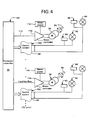
- the computer control system 100 comprises a computer/controller 99, a switch system 102 comprising clutch control logic for every pin, motors 50 including motor controllers 114, and a clutch 60 for controlling the drive to each pin.
- the control logic for an individual pin of the adjustable die operates in the preferred embodiment as follows:
- Computer/controller 99 retrieves from memory storage, or, is input with a three-dimensional array of information representing the positions of each pin of the matrix of pins necessary to describe a three dimensional surface.
- the computer 99 is programmed to determine the extension required of each pin 15 of the die, and controls each individual switching system 102a as depicted in Figure 5.
- Pin extension information which may comprise a number representing the amount of count pulses necessary to achieve the desired translation of that pin relative to a zero (fully retracted) or "home" position, is transferred to a storage register 125 associated with that particular pin. It should be understood that with appropriate software programming, individual pin position information may consist of a number representing the amount of count pulses necessary to achieve a desired translation of that pin relative to any predetermined position and not necessarily a zero or fully retracted position.
- a data storage register 125 is provided for each pin 15 of the die.
- the data is transferred to the register 125 from the computer 99 via any appropriate data transfer configuration/protocol known to those skilled in the art.
- pin extension data is provided to the storage register 125 on data bus 129.
- Pin address information is likewise provided to an address decoder 131a on data address bus 139.
- the decoder 131a addresses the particular data storage register in which information is to be stored.
- the computer 99 issues a STORE command line 127 to the pin data register to initiate the transfer of pin extension information to the addressed storage register 125.
- additional circuitry such as AND gates 133a,b may be needed for writing data to the register 125 or for reading data from the digital counter 135, as will be explained below.
- pin address information is also provided to address decoder 131b on data address bus 139.
- the decoder 131b addresses a counter 135 that is used to count the lead screw position/turns for the addressed pin. Counting the turns of the pin drive shaft 56 is accomplished by the rotary shaft encoder 75 which simply provides a count pulse for each turn of the lead screw engaged thereto. The count of each shaft for each pin may be reset to zero upon initialization. The number of pulses are counted by up/down counter 135 to determine the total amount of pin drive shaft 56 rotations and this number is communicated to a first input A of a digital comparator 141 via count bus 149.
- the current value of the count number is compared with the pin extension count value data value for that particular pin which is communicated to a second input B of the digital comparator 141.
- the output 145 generated by comparator 141 is used to control a switch 147 that activates/de-activates the clutch 60 and the brake 85 corresponding to the addressed pin.
- the clutch is activated and the drive shaft will engage the lead screw for that particular pin as it is being driven to its desired position.
- the current count value of the rotary encoder 75 at input A is equal to or greater than the programmed value for the extension limit of the pin, i.e., if A ⁇ B, then the clutch will be deactivated and the drive shaft will no longer engage the lead screw for that particular pin.
- the power-off brake 85 for that particular pin will be deactivated as power is being supplied thereto.
- the condition A ⁇ B is reached, the power flow to brake 85 will be interrupted, and the brake will provide a stop to the pin at its programmed position.
- Limit switches may be provided with precise, repeatable "on-off” triggers to provide a "home” position in either the fully extended or fully retracted pin positions.
- the individual rotary encoders 75 may then provide incremental positioning information for communication to the computer control system 100 relative to either a "home” position, or from any other known position so that the contoured surface formed by the face of the pins can be modified slightly without having to return to a "home” position.
- the final coordinates of the positioning of each vertical pin location (relative to a "home” position) can be stored magnetically for future use.
- a pin may be moved up/down to make minor corrections to a desired forming mold, for example, when "tweaking" or making springback adjustments.
- Motion of the pin 15 in both directions can be achieved by reversing the drive motor and activating alternate logic for the digital comparator 141.
- the computer 99 may generate drive signal 143 representing forward or reverse (extension or retraction) of the pin drive.
- this forward/reverse signal 143 is tied to a forward/reverse logic circuit 148, so that the clutch may actuate/de-actuate properly when the pin is being retracted.
- forward/reverse signal 143 is provided to the counter 135 so that the counter 135 may count down from its current value when a pin is being retracted.
- pin data register 125 For instance, during tool prove-out, if a particular pin has to be retracted an incremental amount after reaching its desired position, new positional information has to be loaded within pin data register 125. This value provided to input B will necessarily be less than the current value of the counter 135 provided to input A of the comparator 141. If the current count value of the rotary encoder 75 at input A is greater than the programmed count value for the extension limit of the pin at input B, i.e., if A > B, and the forward/reverse signal 143 indicates reverse motion of the pin, then the clutch is activated and the drive shaft will engage the lead screw for that particular pin as it is being retracted to its desired position.
- each pin 15 of the adjustable form die 10 is provided with its own control circuitry 102a and logic thereby permitting all pins to be simultaneously driven.
- there will be seventy-two (72) switching systems 102 each comprising forty-eight (48) individual control circuits 102a ( Figure 5).
- forty-eight (48) switching systems 102 for the adjustable form die each comprising seventy-two (72) individual control circuits 102a.
- the adjustable form die 10 is completely controlled by a computer/controller 99 with only a system of clutch switches 147 and a drive motor 50 as hardware elements.
- the computer 99 selects each pin clutch in sequence and then determines the motion required for that pin.
- the motor will drive the worm gear shaft and that motion will be sensed with the appropriate sensors as described above so that the CPU will simultaneously compare the current shaft position with programmed pin motion criteria.
- the computer may then activate/deactivate all of the clutches 60 via switches 147.
- Shaft position could be fed to the computer with a shaft encoder, as described above, or, the motor could be of the stepping variety that will accurately and definitively move precise amounts in response to command pulses.
- stepping motor/controller 114 is utilized and the computer 99 will generate the motor advance pulses.
- Motion can be provided for forward and reverse operation with appropriate pulse lines and commercially available motor controllers which provides a very high torque, precise angular motion, and virtually no accumulation of errors. It is desirable that the holding torque is also high, and as long as the motor is not overloaded or driven too fast, the position of the pin is accurately known as a function of the number of pulses/counts presented to the controllers. Since the computer 99 generates the pulse count information, it is available to control each clutch switch 147 as described above.
- the main computer/controller 99 would do the surface computations, and determine the required pin extension positions.
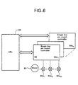
- the pin extension information is transferred to a number of smaller microcomputers/controllers 99a 1 to 99a n as shown in Figure 6 that would replace the switching system 102 described above.
- the smaller microcomputer/controllers are loaded with a program that could control the motor drive 50 for a single line of pins.
- the controller for e.g., 99a 1 , would scan the array of pin locations, determine the clutches 60a 1 through 60a m that should be activated, broadcast appropriate control bits to activate them, and, drive the motor to the first position requiring a change to the clutch actuation conditions. Appropriate changes would be made to clutch actuation, and the motor would then be driven to the next location (pin distance), and the cycle repeated.
- the microcontrollers need to provide motor control codes to position the pins, in addition to appropriate codes for actuating the clutches.
- the motors could be moved at high speed from one clutch activation change location to another, and dwell for only the time required for the clutch to change state.
Landscapes
- Engineering & Computer Science (AREA)
- Mechanical Engineering (AREA)
- Moulds For Moulding Plastics Or The Like (AREA)
- Bending Of Plates, Rods, And Pipes (AREA)
- Mechanical Operated Clutches (AREA)
Claims (27)
- Matrice réglable automatiquement pour former une surface de matrice à contour tridimensionnel, comprenant :caractérisée par :(a) une pluralité de moyens formant broches individuelles (15) définissant une matrice de rangées (12a) de broches et de colonnes (12b) de broches, chacun desdits moyens formant broches étant mobile indépendamment dans une position déployée et rétractée le long d'un axe unique ;(b) un moyen de commande destiné à générer de l'information de position souhaitée pour chacun desdits plusieurs moyens formant broches individuelles de ladite matrice ;(c) des moyens d'entraínement comportant un moteur (50) d'entraínement destiné à entraíner au moins un premier arbre d'entraínement (56) pour entraíner au moins l'une de chacune desdites rangées-colonnes desdits moyens formant broches ;
des moyens (60) d'engagement de couple correspondant à, et connectés de manière fonctionnelle avec, chacun desdits moyens formant broches, chacun desdits moyens d'engagement de couple engageant sélectivement ledit, ou l'un desdits, premiers arbres d'entraínement pour appliquer sélectivement un couple auxdits moyens formant broches correspondants, lesdits moyens d'entraínement et lesdits moyens d'engagement de couple étant sensibles à de l'information de position générée par ledit moyen de commande dans le but de procurer un déplacement axial simultané et indépendant à chacun desdits moyens formant broches de ladite matrice le long de chaque dit axe unique respectif. - Matrice réglable automatiquement selon la revendication 1, et comprenant une pluralité de premiers arbres d'entraínement, un pour chaque rangée / colonne de ladite matrice de moyens formant broches, dans laquelle chaque dit premier arbre d'entraínement comporte une pluralité d'engrenages à vis sans fin (55a) tournant conjointement avec celui-ci et espacés au niveau de chaque emplacement de broche.
- Matrice réglable automatiquement selon la revendication 1 ou 2, dans laquelle ledit moyen d'entraínement comprend en outre une pluralité de seconds moyens formant arbres d'entraínement, chaque second moyen formant arbre d'entraínement étant associé avec un engrenage à vis sans fin correspondant, et connecté de manière fonctionnelle avec celui-ci, pour recevoir un mouvement de rotation de celui-ci, lesdits seconds moyens formant arbres d'entraínement mobiles en rotation étant filetés à une extrémité pour venir en prise avec un moyen formant broche correspondant.
- Matrice réglable automatiquement selon la revendication 3, dans laquelle chaque dit moyen (60) d'engagement de couple est sensible à un premier signal de commande généré par ledit moyen de commande pour engager lesdits premiers moyens formant arbres d'entraínement avec lesdits seconds moyens formant arbres d'entraínement, pour obtenir un déplacement axial desdits moyens formant broches (15) vers une position souhaitée, et en réponse à un second signal de commande, pour dégager lesdits premiers moyens formant arbres d'entraínement desdits seconds moyens formant arbres d'entraínement pour terminer le déplacement axial desdits moyens formant broches.
- Matrice réglable automatiquement selon la revendication 4, dans laquelle chacun desdits moyens (60) d'engagement de couple comprend un moyen de commutation sensible à un premier signal de commande pour permettre un engagement desdits premiers et seconds moyens formant arbres d'entraínement, et sensible audit second signal de commande pour permettre un dégagement desdits premiers et seconds moyens formant arbres d'entraínement.
- Matrice réglable automatiquement selon l'une quelconque des revendications 3 à 5, dans laquelle chacun desdits seconds arbres d'entraínement est placé sensiblement perpendiculairement à son premier moyen formant arbre d'entraínement respectif.
- Matrice réglable automatiquement selon l'une quelconque des revendications 3 à 6, dans laquelle chacun desdits moyens formant broches (15) comprend un moyen destiné à convertir un mouvement de rotation desdits seconds moyens formant arbres d'entraínement en déplacement de déploiement ou de retrait de ses moyens formant broches le long dudit axe unique.
- Matrice réglable automatiquement selon la revendication 7, dans laquelle chacun desdits moyens de conversion desdits moyens formant broches (15) comprend une partie intérieure creuse taraudée destinée à recevoir ledit second moyen formant arbre d'entraínement.
- Matrice réglable automatiquement selon l'une quelconque des revendications précédentes, dans laquelle chacun desdits premiers moyens formant arbres d'entrainement tourne autour d'un axe sensiblement perpendiculaire audit axe unique desdits moyens formant broches (15).
- Matrice réglable automatiquement selon l'une quelconque des revendications précédentes, dans laquelle chacun desdits moyens formant broches (15) comprend un moyen de freinage destiné à activer un arrêt positif desdits moyens formant broches lorsque ladite broche a atteint une position souhaitée.
- Matrice réglable automatiquement selon la revendication 10, dans laquelle ledit moyen de commande permet simultanément auxdits moyens de freinage d'activer ledit arrêt positif et auxdits moyens (60) d'engagement de couple de dégager chacun desdits moyens formant broches (15) de son déplacement axial continu.
- Matrice réglable automatiquement selon la revendication 10, dans laquelle ledit moyen (60) de commande permet auxdits moyens de freinage de maintenir la position souhaitée de leurs moyens formant broches respectifs (15) en réponse audit second signal de commande généré par ledit moyen de commande.
- Matrice réglable automatiquement selon l'une quelconque des revendications précédentes, dans laquelle ledit moyen (60) de commande inclut un moyen de mémorisation de données associé à chaque moyen formant broche (15) pour mémoriser de l'information de position souhaitée pour ce moyen formant broche.
- Matrice réglable automatiquement selon l'une quelconque des revendications précédentes lorsqu'elle dépend de la revendication 3, dans laquelle ledit moyen (60) de commande comprend en outre un moyen formant codeur rotatif associé à chaque moyen formant broche individuelle (15) et connecté avec chacun desdits seconds moyens formant arbres d'entraínement pour compter le nombre de rotations desdits seconds moyens formant arbres d'entraínement, dans laquelle chaque rotation dudit second arbre d'entraínement indique un déplacement, desdits moyens formant broches le long dudit axe unique, ledit moyen formant codeur rotatif générant un signal impulsionnel pour chaque rotation détectée dudit second moyen formant arbre d'entraínement.
- Matrice réglable automatiquement selon la revendication 14, dans laquelle ledit système de commande comprend en outre un moyen formant compteur associé à chacun desdits moyens formant broches (15) de ladite matrice et communiquant avec ledit moyen formant codeur rotatif dans le but de compter le nombre de signaux impulsionnels générés par celui-ci, ledit moyen formant compteur générant un signal de sortie de compteur représentant le positionnement axial, ou courant, de son moyen formant broche associé.
- Matrice réglable automatiquement selon la revendication 15, comprenant en outre un moyen formant comparateur (141) associé à chaque moyen formant broche individuel (15), dans laquelle ledit signal de sortie de compteur courant d'un moyen formant broche respectif est délivré à une première entrée dudit comparateur, et ladite information de position souhaitée mémorisée pour ce moyen formant broche est délivrée à une seconde entrée dudit comparateur, ledit comparateur comparant une différence entre ses dites première et seconde entrées et générant ledit premier signal de commande indiquant que ledit moyen formant broche n'a pas atteint une position finale, et générant ledit second signal de commande indiquant que ledit moyen formant broche a atteint ladite position finale.
- Matrice réglable automatiquement selon la revendication 16, dans laquelle ledit moyen de commutation associé à chacun desdits moyens formant broches est sensible audit second signal de commande pour désactiver ledit dispositif d'engagement de couple pour terminer le déplacement dudit moyen formant broche (15) lorsque lesdites première et seconde entrées sont égales.
- Matrice réglable automatiquement selon la revendication 16, dans laquelle ledit moyen de commutation associé à chacun desdits moyens formant broches (15) est sensible audit premier signal de commande pour activer ledit dispositif d'engagement de couple pour permettre un déplacement dudit moyen formant broche lorsque lesdites première et seconde entrées ne sont pas égales.
- Matrice réglable automatiquement selon la revendication 13, dans laquelle ledit moyen de commande comprend en outre un dispositif formant ordinateur destiné à entrer de l'information de position souhaitée concernant ladite pluralité de moyens formant broches dans lesdits moyens de mémorisation de données respectifs associés auxdits plusieurs moyens formant broches.
- Matrice réglable automatiquement selon l'une quelconque des revendications précédentes, dans laquelle chacun desdits moteurs (50) d'entraínement permet une rotation dans le sens vers l'avant ou en sens contraire desdits premiers moyens formant arbres d'entraínement, chacun desdits moyens formant broches (15) se déplaçant vers une position déployée le long dudit axe unique lorsque ledit premier moyen formant arbre d'entraínement tourne dans le sens vers l'avant et se déplaçant dans une position rétractée lorsque ledit premier moyen formant arbre d'entraínement tourne dans un sens contraire.
- Matrice réglable automatiquement selon l'une quelconque des revendications précédentes, dans laquelle ledit moyen de commande calcule des données de position souhaitée pour changer la position de l'un desdits moyens formant broches (15) par rapport à une position de repos prédéterminée.
- Matrice réglable automatiquement selon la revendication 21, dans laquelle ladite position de repos prédéterminée correspond à une position dans laquelle chacun desdits moyens formant broches (15) se trouve dans une position complètement rétractée.
- Matrice réglable automatiquement selon la revendication 21, dans laquelle ladite position de repos prédéterminée correspond à une position dans laquelle chacun desdits moyens formant broches (15) se trouve dans une position complètement déployée.
- Procédé de formage d'une matrice d'emboutissage comportant une pluralité de moyens formant broches (15) agencés en une matrice comprenant une pluralité de rangées / colonnes, ladite matrice incluant des moyens d'entraínement comportant un moteur d'entraínement pour chaque rangée / colonne de ladite matrice de broches pour faire tourner un premier arbre d'entraínement, et des moyens (60) d'engagement de couple correspondant à, et connectés de manière fonctionnelle avec, chacun desdits moyens formant broches, destinés à engager sélectivement lesdits moyens formant broches pour appliquer sélectivement un couple auxdits moyens formant broches correspondants, lesdits moyens d'entraínement et lesdits moyens d'engagement de couple étant destinés à entraíner indépendamment chaque moyen formant broche individuelle (15) de ladite pluralité de moyens formant broches vers une position souhaitée le long d'un axe unique, ledit procédé comprenant les étapes, dans lesquelles :(a) on génère de l'information de déploiement de moyens formant broches, pour chaque moyen formant broche de ladite matrice, nécessaire pour former une surface à contour tridimensionnel souhaitée ;(b) on transfère chaque dite information de déploiement de moyens formant broches à un moyen de mémorisation de données correspondant à chacun desdits moyens formant broches ;(c) on active lesdits moyens d'entraínement pour entraíner chacun desdits moyens formant broches de ladite matrice vers sa position déployée souhaitée, tandis que(d) on compare simultanément la position réelle de chacun desdits moyens formant broches avec l'information de position de moyen formant broche souhaitée mémorisée dans son moyen de mémorisation de données respectif ; et(c) on termine le déplacement dudit moyen formant broche lorsque la position réelle de ce moyen formant broche est égale à la position souhaitée mémorisée dans ledit moyen de mémorisation de données.
- Procédé de formage d'une matrice d'emboutissage selon la revendication 24, dans lequel l'étape (d) de comparaison comprend en outre l'étape de production d'un premier signal de commande pour permettre un engagement continu desdits moyens (60) d'engagement de couple avec lesdits moyens d'entraínement lorsque ladite position réelle desdits moyens formant broches (15) n'a pas atteint la position de broche souhaitée.
- Procédé de formage d'une matrice d'emboutissage selon la revendication 24 ou la revendication 25, dans lequel ladite étape (d) comprend en outre l'étape de production d'un second signal de commande pour dégager lesdits moyens d'engagement de couple desdits moyens d'entraínement lorsque ladite position réelle desdits moyens formant broches a atteint sa position de broche souhaitée.
- Procédé de formage d'une matrice d'emboutissage selon la revendication 25, dans lequel ladite étape (d) comprend en outre l'étape d'activation d'un arrêt positif par des moyens de freinage pour empêcher un déplacement plus avant desdits moyens formant broches (15) lors de la réception dudit second signal de commande.
Applications Claiming Priority (3)
| Application Number | Priority Date | Filing Date | Title |
|---|---|---|---|
| US349434 | 1994-12-05 | ||
| US08/349,434 US5546784A (en) | 1994-12-05 | 1994-12-05 | Adjustable form die |
| PCT/US1995/015423 WO1996017697A1 (fr) | 1994-12-05 | 1995-11-27 | Matrice d'emboutissage ajustable |
Publications (3)
| Publication Number | Publication Date |
|---|---|
| EP0796155A1 EP0796155A1 (fr) | 1997-09-24 |
| EP0796155A4 EP0796155A4 (fr) | 1998-04-15 |
| EP0796155B1 true EP0796155B1 (fr) | 2001-10-10 |
Family
ID=23372390
Family Applications (1)
| Application Number | Title | Priority Date | Filing Date |
|---|---|---|---|
| EP95940852A Expired - Lifetime EP0796155B1 (fr) | 1994-12-05 | 1995-11-27 | Matrice d'emboutissage ajustable |
Country Status (5)
| Country | Link |
|---|---|
| US (1) | US5546784A (fr) |
| EP (1) | EP0796155B1 (fr) |
| DE (1) | DE69523172T2 (fr) |
| ES (1) | ES2161917T3 (fr) |
| WO (1) | WO1996017697A1 (fr) |
Families Citing this family (87)
| Publication number | Priority date | Publication date | Assignee | Title |
|---|---|---|---|---|
| US5722646A (en) * | 1995-08-29 | 1998-03-03 | Cna Manufacturing Systems, Inc. | Flexible tooling apparatus |
| US5829151A (en) * | 1996-12-20 | 1998-11-03 | The Boeing Company | Multi-axis part positioning system |
| US6012314A (en) * | 1997-07-30 | 2000-01-11 | Northrop Grumman Corporation | Individual motor pin module |
| US5954175A (en) * | 1997-09-02 | 1999-09-21 | Northrop Grumman Corporation | Modularized parallel drivetrain |
| US6202275B1 (en) * | 1997-12-12 | 2001-03-20 | Maglev, Inc. | Precision assembly table and method |
| US6250619B1 (en) | 1998-02-03 | 2001-06-26 | Cna Manufacturing Systems, Inc. | Clamp suitable for use at high temperatures in a flexible tooling apparatus |
| US6032348A (en) * | 1998-03-20 | 2000-03-07 | Northrop Grumman Corporation | Method of forming a modularized adjustable holding fixture |
| US6053026A (en) * | 1998-10-07 | 2000-04-25 | Northrop Grumman Corporation | Block-set form die assembly |
| US6089061A (en) * | 1999-05-12 | 2000-07-18 | Northrop Grumman Corporation | Modularized reconfigurable heated forming tool |
| US6035691A (en) * | 1999-08-10 | 2000-03-14 | Lin; Ruey-Mo | Adjustable rod bending device for a corrective spinal rod which is used in a surgical operation |
| US6578399B1 (en) | 1999-09-09 | 2003-06-17 | Northrop Grumman Corporation | Single-die modularized, reconfigurable honeycomb core forming tool |
| US6209380B1 (en) * | 2000-02-28 | 2001-04-03 | Northrop Grumman Corporation | Pin tip assembly in tooling apparatus for forming honeycomb cores |
| US6363767B1 (en) * | 2000-02-29 | 2002-04-02 | Northrop Grumman Corporation | System and method for forming sheet metal using a reconfigurable tool |
| US6484776B1 (en) * | 2000-04-07 | 2002-11-26 | Northrop Grumman Corporation | System for constructing a laminate |
| DE10043209A1 (de) * | 2000-09-01 | 2002-04-04 | Esc Gmbh & Co Kg Extended Stru | Flexibles Werkzeug zur Umformung eines Werkstücks |
| US6700563B1 (en) | 2000-09-29 | 2004-03-02 | Intel Corporation | 3D encoder |
| US6734785B2 (en) * | 2000-10-27 | 2004-05-11 | Robert C. Petersen | Tactile display system |
| DE60206359T2 (de) * | 2001-02-14 | 2006-06-14 | Surface Generation Ltd | Werkstückträger |
| JP2003053791A (ja) * | 2001-08-22 | 2003-02-26 | Mitsubishi Electric Corp | 半導体製造装置及び該装置により製造された半導体装置 |
| US7194388B2 (en) * | 2002-03-25 | 2007-03-20 | Alcoa Inc. | Method for determining a die profile for forming a metal part having a desired shape and associated methods |
| WO2004004979A1 (fr) * | 2002-07-08 | 2004-01-15 | Airline Hydraulics Corporation | Montage de support a blocage |
| WO2004113015A2 (fr) * | 2003-06-20 | 2004-12-29 | Par Systems, Inc. | Appareil fixe flexible |
| US7306463B2 (en) | 2004-07-19 | 2007-12-11 | Brian Paul Hanley | Pseudo-cuneiform tactile display |
| US7942394B2 (en) * | 2005-01-07 | 2011-05-17 | Dek International Gmbh | Locking support fixture |
| WO2007014251A2 (fr) * | 2005-07-25 | 2007-02-01 | Robotic Solutions, Inc. | Appareil porte-piece |
| CN100363126C (zh) * | 2005-08-10 | 2008-01-23 | 中国科学院金属研究所 | 一种板材液压或气压成形方法及装置 |
| US7913729B2 (en) * | 2005-11-22 | 2011-03-29 | Anthony Brcich | Molding coping fixture |
| CN101389420A (zh) * | 2006-01-25 | 2009-03-18 | 联邦科学技术研究组织 | 主动可重构的拉伸成形 |
| JP4932899B2 (ja) * | 2006-04-05 | 2012-05-16 | シンセス ゲゼルシャフト ミット ベシュレンクテル ハフツング | 解剖学的な目標形状に従って予成形された人体あるいは動物体のための平型インプラントを製造するための方法および装置 |
| GB0612594D0 (en) * | 2006-06-24 | 2006-08-02 | Surface Generation Ltd | Improved tooling system |
| GB2442793A (en) * | 2006-10-10 | 2008-04-16 | Apogee Antennas Ltd | Forming curved panels |
| US8046098B2 (en) * | 2007-01-08 | 2011-10-25 | Jeom Kee Paik | Curved surface forming method of a metal plate |
| DE102007009597B4 (de) | 2007-02-26 | 2015-12-17 | Adrian Holzhauser | Verfahren und Vorrichtung zum Verformen von Blechen und Kunststoffen |
| US7997891B2 (en) * | 2007-04-12 | 2011-08-16 | Purdue Research Foundation | Molding processes and tool therefor |
| US9352373B2 (en) * | 2007-06-01 | 2016-05-31 | The University Of Queensland | Assembly and method for press forming a deformable material |
| US20080302500A1 (en) * | 2007-06-07 | 2008-12-11 | The Boeing Company | Reusable mold forming tool |
| US8118959B2 (en) | 2007-06-27 | 2012-02-21 | The Boeing Company | Method and apparatus for contouring composite pre-preg articles |
| CN101868323B (zh) * | 2007-11-30 | 2014-10-29 | Flow国际公司 | 用于对工件进行机械加工的柔性支撑系统 |
| US8322176B2 (en) * | 2009-02-11 | 2012-12-04 | Ford Global Technologies, Llc | System and method for incrementally forming a workpiece |
| CN101549377B (zh) * | 2009-03-12 | 2011-01-12 | 泰安市硕力液压设备厂 | 方形压头可调活络模具板材曲面成形装置 |
| CN102549511B (zh) * | 2009-08-06 | 2014-12-17 | 美国派尔(PaR)系统有限公司 | 柔性固定设备 |
| NL1037301C2 (nl) * | 2009-09-21 | 2011-03-22 | Sebastiaan Henri Alphons Boers | Systeem voor het besturen van een pennenbedmal. |
| US10060001B2 (en) | 2010-07-26 | 2018-08-28 | The Boeing Company | Tooling system for processing workpieces |
| US8966763B1 (en) * | 2010-07-26 | 2015-03-03 | The Boeing Company | Tooling system for processing workpieces |
| KR101234506B1 (ko) | 2010-09-20 | 2013-02-20 | 한국기계연구원 | 가변블럭조립체가 구비된 후판 성형 장치 |
| US8734703B2 (en) | 2010-11-11 | 2014-05-27 | Spirit Aerosystems, Inc. | Methods and systems for fabricating composite parts using a SMP apparatus as a rigid lay-up tool and bladder |
| US8945325B2 (en) | 2010-11-11 | 2015-02-03 | Spirit AreoSystems, Inc. | Methods and systems for forming integral composite parts with a SMP apparatus |
| US9073240B2 (en) | 2010-11-11 | 2015-07-07 | Spirit Aerosystems, Inc. | Reconfigurable shape memory polymer tooling supports |
| US8815145B2 (en) | 2010-11-11 | 2014-08-26 | Spirit Aerosystems, Inc. | Methods and systems for fabricating composite stiffeners with a rigid/malleable SMP apparatus |
| CN103338874B (zh) * | 2011-01-28 | 2015-10-21 | 丰田自动车株式会社 | 冲压成形用模具 |
| CN102135224A (zh) * | 2011-03-23 | 2011-07-27 | 吉林大学 | 一种多点调形装置 |
| DE102011104366A1 (de) * | 2011-06-16 | 2012-12-20 | Daimler Ag | Drapier- und Formpresswerkzeug und Verfahren zur Herstellung einer Preform und eines Faserkunststoffverbundbauteils |
| DE102011053118C5 (de) * | 2011-08-30 | 2021-08-05 | Kirchhoff Automotive Deutschland Gmbh | Verfahren zum Herstellen eines pressgehärteten Formteils sowie Presshärtwerkzeug |
| JP6036555B2 (ja) * | 2013-05-29 | 2016-11-30 | トヨタ紡織株式会社 | プレス金型 |
| US9664265B2 (en) | 2013-09-12 | 2017-05-30 | Massachusetts Institute Of Technology | Methods and apparatus for selective rod actuation |
| CN103495635B (zh) * | 2013-09-30 | 2015-04-08 | 中国航空工业集团公司北京航空制造工程研究所 | 采用柔性多点模具过渡型面的蒙皮拉形方法 |
| US9921572B2 (en) | 2013-11-12 | 2018-03-20 | Embraer S.A. | Springback compensation in formed sheet metal parts |
| US11407033B2 (en) * | 2014-01-14 | 2022-08-09 | Hoden Seimitsu Kako Kenkyusho Co., Ltd. | Three-dimensional shaping apparatus |
| US20150336227A1 (en) * | 2014-05-20 | 2015-11-26 | GM Global Technology Operations LLC | Reconfigurable fixture for sheet metal parts and method |
| JP6411785B2 (ja) * | 2014-06-18 | 2018-10-24 | 株式会社放電精密加工研究所 | 三次元造形装置 |
| CN104138949B (zh) * | 2014-06-27 | 2016-08-03 | 江西理工大学 | 一种金属板材多点复合渐进成形装置 |
| CN106660226B (zh) * | 2014-08-19 | 2019-06-11 | 庆熙大学校产学协力团 | 非定型成型体制作装置、利用其的成型物质铸型及杆形模具 |
| US9981302B2 (en) * | 2014-09-30 | 2018-05-29 | Apple Inc. | Versatile dynamic stamping/restriking tool |
| US9481026B2 (en) * | 2014-10-27 | 2016-11-01 | Tyco Electronics Corporation | Press device with adjustment mechanism |
| CN104384356B (zh) * | 2014-11-28 | 2016-08-17 | 黑龙江中科诺晟自动化设备开发有限公司 | 一种点阵式模具自动成型设备中与驱动丝杠对应的离合器的串行控制装置 |
| JP6069385B2 (ja) * | 2015-02-27 | 2017-02-01 | アイダエンジニアリング株式会社 | 板状金属材料の曲げ成形装置及び成形方法 |
| US20170050322A1 (en) * | 2015-08-19 | 2017-02-23 | GM Global Technology Operations LLC | Fixture and system |
| DE102015011633A1 (de) | 2015-09-07 | 2017-03-09 | Jürgen Bast | Verfahren und Vorrichtung zur Erzeugung von direkt aus CAD-Daten gebildeten multifunktionalen 3-D-Flächen und deren Fixierung durch einen magnetorheologischen Effekt |
| DE102015118606B4 (de) * | 2015-10-30 | 2023-01-12 | Voestalpine Metal Forming Gmbh | Werkzeug zum Tiefziehen und Verfahren zu seiner Herstellung |
| US11370014B2 (en) * | 2016-09-26 | 2022-06-28 | Sharif University Of Technology | System and method for passive pin positioning and locking for reconfigurable forming dies |
| DE102016225986A1 (de) * | 2016-12-22 | 2018-06-28 | Bayerische Motoren Werke Aktiengesellschaft | Vorrichtung und Verfahren zum Formen eines Bleches |
| US11734477B2 (en) * | 2018-03-08 | 2023-08-22 | Concurrent Technologies Corporation | Location-based VR topological extrusion apparatus |
| CN108237174B (zh) * | 2018-03-27 | 2019-07-26 | 重庆长安汽车股份有限公司 | 适用于冲压凸模上的平衡块检测系统 |
| DE102018107391B4 (de) * | 2018-03-28 | 2022-08-18 | MDS e.K. | Säulensystem |
| KR102459994B1 (ko) * | 2018-05-21 | 2022-10-28 | 한국전자통신연구원 | 재구성 가능한 지그 장치 |
| US11090149B2 (en) | 2018-09-28 | 2021-08-17 | DePuy Synthes Products, Inc. | Inflatable orbital implant for repositioning an eyeball, and related methods |
| US11001016B2 (en) | 2019-04-22 | 2021-05-11 | Massachusetts Institute Of Technology | Methods and apparatus for reconfigurable heated mold |
| US11022953B2 (en) | 2019-05-07 | 2021-06-01 | Cna Manufacturing Systems, Inc. | Flexible tooling system |
| WO2022162207A1 (fr) | 2021-02-01 | 2022-08-04 | Hamoud Mohamed | Moule pour former de manière flexible une surface de moule |
| KR102472277B1 (ko) * | 2021-03-08 | 2022-11-30 | 상신브레이크주식회사 | 자동차 브레이크패드 성형기용 상층재 다짐장치 |
| WO2022246249A1 (fr) * | 2021-05-21 | 2022-11-24 | Muse Engine, LLC | Moule reconfigurable et sous-système de moulage pour moulage par injection et applications de fabrication additive tridimensionnelle |
| CN114038336B (zh) * | 2021-12-06 | 2023-02-07 | 武汉华星光电半导体显示技术有限公司 | 仿形装置、显示面板的制作方法及显示面板 |
| CN114713661B (zh) * | 2022-04-13 | 2024-01-26 | 重庆电子工程职业学院 | 一种参照工件回弹参数对冲压模具进行修模的方法 |
| JP7826898B2 (ja) * | 2022-10-25 | 2026-03-10 | 株式会社豊田中央研究所 | 逐次成形装置および逐次成形方法 |
| CN115870408A (zh) * | 2023-01-03 | 2023-03-31 | 奇瑞汽车股份有限公司 | 钣金模具 |
| DE102023107386A1 (de) * | 2023-03-23 | 2024-09-26 | Desconpro Engineering Gmbh | Adaptive Form |
| US12509259B1 (en) * | 2023-05-23 | 2025-12-30 | Amazon Technologies, Inc. | Bundling system for banding item(s) |
Family Cites Families (4)
| Publication number | Priority date | Publication date | Assignee | Title |
|---|---|---|---|---|
| US4131003A (en) * | 1977-06-07 | 1978-12-26 | The Boeing Company | Semiautomatic control system for tube bending machine |
| US4212188A (en) * | 1979-01-18 | 1980-07-15 | The Boeing Company | Apparatus for forming sheet metal |
| US4548065A (en) * | 1983-05-27 | 1985-10-22 | Rockwell International Corporation | Stretch-forming tool |
| JP2774976B2 (ja) * | 1990-02-13 | 1998-07-09 | 株式会社モリタアンドカンパニー | 板ばねのキャンバー成形方法およびその装置 |
-
1994
- 1994-12-05 US US08/349,434 patent/US5546784A/en not_active Expired - Fee Related
-
1995
- 1995-11-27 DE DE69523172T patent/DE69523172T2/de not_active Expired - Fee Related
- 1995-11-27 EP EP95940852A patent/EP0796155B1/fr not_active Expired - Lifetime
- 1995-11-27 WO PCT/US1995/015423 patent/WO1996017697A1/fr not_active Ceased
- 1995-11-27 ES ES95940852T patent/ES2161917T3/es not_active Expired - Lifetime
Also Published As
| Publication number | Publication date |
|---|---|
| ES2161917T3 (es) | 2001-12-16 |
| DE69523172D1 (de) | 2001-11-15 |
| EP0796155A4 (fr) | 1998-04-15 |
| EP0796155A1 (fr) | 1997-09-24 |
| DE69523172T2 (de) | 2002-06-06 |
| WO1996017697A1 (fr) | 1996-06-13 |
| US5546784A (en) | 1996-08-20 |
Similar Documents
| Publication | Publication Date | Title |
|---|---|---|
| US5546784A (en) | Adjustable form die | |
| US3951271A (en) | Robot control device | |
| US3299681A (en) | Program controlled tube bender | |
| US4469993A (en) | Programmable multiple position machine | |
| US4401930A (en) | Method of sensing position of movable body and apparatus therefor | |
| EP1015993B1 (fr) | Module individuel de broche de moteur | |
| US7293500B2 (en) | Press | |
| EP0901876B1 (fr) | Couplage d'entraínement parallèle modulaire | |
| US4527244A (en) | Electro-hydraulic position control for a machine tool with actual and commanded position feedback | |
| CN103302820A (zh) | 注射成形机 | |
| GB2098578A (en) | An industrial production system served by a plurality of operating arms and controlled by a computer system | |
| US3899724A (en) | Setting up machine including computer-controlled positioner for machine part adjusting element | |
| CN109263046A (zh) | 一种基于螺旋线的3d打印系统 | |
| JP5356058B2 (ja) | ロータリ射出成形機 | |
| US20030141632A1 (en) | Adjusting system for a die | |
| EP0273559B1 (fr) | Dispositif pour distribuer des gouttes dans une machine pour former des bouteilles | |
| EP0063466B1 (fr) | Méthode pour détecter la position d'un élément mobile | |
| EP3092091B1 (fr) | Machine de pliage de tôle | |
| WO2018041603A1 (fr) | Machine de traitement comprenant plusieurs postes de traitement pour le traitement de corps | |
| TWM650103U (zh) | 鍛造部品成型機之模具換位裝置 | |
| JPH03155499A (ja) | モータプレス機の制御方法 | |
| JP4440790B2 (ja) | 成形機及び成形機の成形条件設定方法 | |
| US1288648A (en) | Flanging-press. | |
| JPH0635145B2 (ja) | パリソンの偏肉調整装置 | |
| SU617122A1 (ru) | Устройство дл вырубки деталей из листового материала |
Legal Events
| Date | Code | Title | Description |
|---|---|---|---|
| PUAI | Public reference made under article 153(3) epc to a published international application that has entered the european phase |
Free format text: ORIGINAL CODE: 0009012 |
|
| 17P | Request for examination filed |
Effective date: 19970704 |
|
| AK | Designated contracting states |
Kind code of ref document: A1 Designated state(s): CH DE ES FR GB IT LI SE |
|
| RIN1 | Information on inventor provided before grant (corrected) |
Inventor name: KESSELMAN, MARTIN Inventor name: HAAS, EDWIN, G. |
|
| A4 | Supplementary search report drawn up and despatched |
Effective date: 19980225 |
|
| AK | Designated contracting states |
Kind code of ref document: A4 Designated state(s): CH DE ES FR GB IT LI SE |
|
| 17Q | First examination report despatched |
Effective date: 19990701 |
|
| RAP1 | Party data changed (applicant data changed or rights of an application transferred) |
Owner name: NORTHROP GRUMMAN CORPORATION |
|
| GRAG | Despatch of communication of intention to grant |
Free format text: ORIGINAL CODE: EPIDOS AGRA |
|
| GRAG | Despatch of communication of intention to grant |
Free format text: ORIGINAL CODE: EPIDOS AGRA |
|
| GRAH | Despatch of communication of intention to grant a patent |
Free format text: ORIGINAL CODE: EPIDOS IGRA |
|
| GRAH | Despatch of communication of intention to grant a patent |
Free format text: ORIGINAL CODE: EPIDOS IGRA |
|
| GRAA | (expected) grant |
Free format text: ORIGINAL CODE: 0009210 |
|
| AK | Designated contracting states |
Kind code of ref document: B1 Designated state(s): CH DE ES FR GB IT LI SE |
|
| REG | Reference to a national code |
Ref country code: CH Ref legal event code: EP |
|
| REG | Reference to a national code |
Ref country code: CH Ref legal event code: NV Representative=s name: R. A. EGLI & CO. PATENTANWAELTE |
|
| REF | Corresponds to: |
Ref document number: 69523172 Country of ref document: DE Date of ref document: 20011115 |
|
| REG | Reference to a national code |
Ref country code: ES Ref legal event code: FG2A Ref document number: 2161917 Country of ref document: ES Kind code of ref document: T3 |
|
| ET | Fr: translation filed | ||
| REG | Reference to a national code |
Ref country code: GB Ref legal event code: IF02 |
|
| PLBE | No opposition filed within time limit |
Free format text: ORIGINAL CODE: 0009261 |
|
| STAA | Information on the status of an ep patent application or granted ep patent |
Free format text: STATUS: NO OPPOSITION FILED WITHIN TIME LIMIT |
|
| 26N | No opposition filed | ||
| PGFP | Annual fee paid to national office [announced via postgrant information from national office to epo] |
Ref country code: FR Payment date: 20021030 Year of fee payment: 8 |
|
| PGFP | Annual fee paid to national office [announced via postgrant information from national office to epo] |
Ref country code: SE Payment date: 20021031 Year of fee payment: 8 |
|
| PGFP | Annual fee paid to national office [announced via postgrant information from national office to epo] |
Ref country code: CH Payment date: 20021101 Year of fee payment: 8 |
|
| PGFP | Annual fee paid to national office [announced via postgrant information from national office to epo] |
Ref country code: GB Payment date: 20021120 Year of fee payment: 8 |
|
| PGFP | Annual fee paid to national office [announced via postgrant information from national office to epo] |
Ref country code: DE Payment date: 20021202 Year of fee payment: 8 |
|
| PGFP | Annual fee paid to national office [announced via postgrant information from national office to epo] |
Ref country code: ES Payment date: 20021204 Year of fee payment: 8 |
|
| PG25 | Lapsed in a contracting state [announced via postgrant information from national office to epo] |
Ref country code: GB Free format text: LAPSE BECAUSE OF NON-PAYMENT OF DUE FEES Effective date: 20031127 |
|
| PG25 | Lapsed in a contracting state [announced via postgrant information from national office to epo] |
Ref country code: SE Free format text: LAPSE BECAUSE OF NON-PAYMENT OF DUE FEES Effective date: 20031128 Ref country code: ES Free format text: LAPSE BECAUSE OF NON-PAYMENT OF DUE FEES Effective date: 20031128 |
|
| PG25 | Lapsed in a contracting state [announced via postgrant information from national office to epo] |
Ref country code: LI Free format text: LAPSE BECAUSE OF NON-PAYMENT OF DUE FEES Effective date: 20031130 Ref country code: CH Free format text: LAPSE BECAUSE OF NON-PAYMENT OF DUE FEES Effective date: 20031130 |
|
| PG25 | Lapsed in a contracting state [announced via postgrant information from national office to epo] |
Ref country code: DE Free format text: LAPSE BECAUSE OF NON-PAYMENT OF DUE FEES Effective date: 20040602 |
|
| EUG | Se: european patent has lapsed | ||
| GBPC | Gb: european patent ceased through non-payment of renewal fee |
Effective date: 20031127 |
|
| REG | Reference to a national code |
Ref country code: CH Ref legal event code: PL |
|
| PG25 | Lapsed in a contracting state [announced via postgrant information from national office to epo] |
Ref country code: FR Free format text: LAPSE BECAUSE OF NON-PAYMENT OF DUE FEES Effective date: 20040730 |
|
| REG | Reference to a national code |
Ref country code: FR Ref legal event code: ST |
|
| REG | Reference to a national code |
Ref country code: ES Ref legal event code: FD2A Effective date: 20031128 |
|
| PG25 | Lapsed in a contracting state [announced via postgrant information from national office to epo] |
Ref country code: IT Free format text: LAPSE BECAUSE OF NON-PAYMENT OF DUE FEES;WARNING: LAPSES OF ITALIAN PATENTS WITH EFFECTIVE DATE BEFORE 2007 MAY HAVE OCCURRED AT ANY TIME BEFORE 2007. THE CORRECT EFFECTIVE DATE MAY BE DIFFERENT FROM THE ONE RECORDED. Effective date: 20051127 |