EP0796168B1 - Quersiegelvorrichtung für eine schlauchbeutel-verpackungsmaschine - Google Patents
Quersiegelvorrichtung für eine schlauchbeutel-verpackungsmaschine Download PDFInfo
- Publication number
- EP0796168B1 EP0796168B1 EP95936928A EP95936928A EP0796168B1 EP 0796168 B1 EP0796168 B1 EP 0796168B1 EP 95936928 A EP95936928 A EP 95936928A EP 95936928 A EP95936928 A EP 95936928A EP 0796168 B1 EP0796168 B1 EP 0796168B1
- Authority
- EP
- European Patent Office
- Prior art keywords
- jaw
- sealing
- opposite
- stop
- jaws
- Prior art date
- Legal status (The legal status is an assumption and is not a legal conclusion. Google has not performed a legal analysis and makes no representation as to the accuracy of the status listed.)
- Expired - Lifetime
Links
- 238000007789 sealing Methods 0.000 title claims abstract description 31
- 238000004806 packaging method and process Methods 0.000 claims description 5
- 239000000463 material Substances 0.000 abstract description 3
- 230000003111 delayed effect Effects 0.000 abstract description 2
- 230000007246 mechanism Effects 0.000 abstract description 2
- 239000000969 carrier Substances 0.000 description 1
- 239000012530 fluid Substances 0.000 description 1
- 230000036316 preload Effects 0.000 description 1
Images
Classifications
-
- B—PERFORMING OPERATIONS; TRANSPORTING
- B29—WORKING OF PLASTICS; WORKING OF SUBSTANCES IN A PLASTIC STATE IN GENERAL
- B29C—SHAPING OR JOINING OF PLASTICS; SHAPING OF MATERIAL IN A PLASTIC STATE, NOT OTHERWISE PROVIDED FOR; AFTER-TREATMENT OF THE SHAPED PRODUCTS, e.g. REPAIRING
- B29C66/00—General aspects of processes or apparatus for joining preformed parts
- B29C66/01—General aspects dealing with the joint area or with the area to be joined
- B29C66/05—Particular design of joint configurations
- B29C66/10—Particular design of joint configurations particular design of the joint cross-sections
- B29C66/11—Joint cross-sections comprising a single joint-segment, i.e. one of the parts to be joined comprising a single joint-segment in the joint cross-section
- B29C66/112—Single lapped joints
- B29C66/1122—Single lap to lap joints, i.e. overlap joints
-
- B—PERFORMING OPERATIONS; TRANSPORTING
- B29—WORKING OF PLASTICS; WORKING OF SUBSTANCES IN A PLASTIC STATE IN GENERAL
- B29C—SHAPING OR JOINING OF PLASTICS; SHAPING OF MATERIAL IN A PLASTIC STATE, NOT OTHERWISE PROVIDED FOR; AFTER-TREATMENT OF THE SHAPED PRODUCTS, e.g. REPAIRING
- B29C65/00—Joining or sealing of preformed parts, e.g. welding of plastics materials; Apparatus therefor
- B29C65/02—Joining or sealing of preformed parts, e.g. welding of plastics materials; Apparatus therefor by heating, with or without pressure
- B29C65/18—Joining or sealing of preformed parts, e.g. welding of plastics materials; Apparatus therefor by heating, with or without pressure using heated tools
-
- B—PERFORMING OPERATIONS; TRANSPORTING
- B29—WORKING OF PLASTICS; WORKING OF SUBSTANCES IN A PLASTIC STATE IN GENERAL
- B29C—SHAPING OR JOINING OF PLASTICS; SHAPING OF MATERIAL IN A PLASTIC STATE, NOT OTHERWISE PROVIDED FOR; AFTER-TREATMENT OF THE SHAPED PRODUCTS, e.g. REPAIRING
- B29C66/00—General aspects of processes or apparatus for joining preformed parts
- B29C66/40—General aspects of joining substantially flat articles, e.g. plates, sheets or web-like materials; Making flat seams in tubular or hollow articles; Joining single elements to substantially flat surfaces
- B29C66/41—Joining substantially flat articles ; Making flat seams in tubular or hollow articles
- B29C66/43—Joining a relatively small portion of the surface of said articles
- B29C66/431—Joining the articles to themselves
- B29C66/4312—Joining the articles to themselves for making flat seams in tubular or hollow articles, e.g. transversal seams
-
- B—PERFORMING OPERATIONS; TRANSPORTING
- B29—WORKING OF PLASTICS; WORKING OF SUBSTANCES IN A PLASTIC STATE IN GENERAL
- B29C—SHAPING OR JOINING OF PLASTICS; SHAPING OF MATERIAL IN A PLASTIC STATE, NOT OTHERWISE PROVIDED FOR; AFTER-TREATMENT OF THE SHAPED PRODUCTS, e.g. REPAIRING
- B29C66/00—General aspects of processes or apparatus for joining preformed parts
- B29C66/80—General aspects of machine operations or constructions and parts thereof
- B29C66/81—General aspects of the pressing elements, i.e. the elements applying pressure on the parts to be joined in the area to be joined, e.g. the welding jaws or clamps
- B29C66/816—General aspects of the pressing elements, i.e. the elements applying pressure on the parts to be joined in the area to be joined, e.g. the welding jaws or clamps characterised by the mounting of the pressing elements, e.g. of the welding jaws or clamps
- B29C66/8161—General aspects of the pressing elements, i.e. the elements applying pressure on the parts to be joined in the area to be joined, e.g. the welding jaws or clamps characterised by the mounting of the pressing elements, e.g. of the welding jaws or clamps said pressing elements being supported or backed-up by springs or by resilient material
-
- B—PERFORMING OPERATIONS; TRANSPORTING
- B29—WORKING OF PLASTICS; WORKING OF SUBSTANCES IN A PLASTIC STATE IN GENERAL
- B29C—SHAPING OR JOINING OF PLASTICS; SHAPING OF MATERIAL IN A PLASTIC STATE, NOT OTHERWISE PROVIDED FOR; AFTER-TREATMENT OF THE SHAPED PRODUCTS, e.g. REPAIRING
- B29C66/00—General aspects of processes or apparatus for joining preformed parts
- B29C66/80—General aspects of machine operations or constructions and parts thereof
- B29C66/82—Pressure application arrangements, e.g. transmission or actuating mechanisms for joining tools or clamps
- B29C66/822—Transmission mechanisms
- B29C66/8221—Scissor or lever mechanisms, i.e. involving a pivot point
-
- B—PERFORMING OPERATIONS; TRANSPORTING
- B29—WORKING OF PLASTICS; WORKING OF SUBSTANCES IN A PLASTIC STATE IN GENERAL
- B29C—SHAPING OR JOINING OF PLASTICS; SHAPING OF MATERIAL IN A PLASTIC STATE, NOT OTHERWISE PROVIDED FOR; AFTER-TREATMENT OF THE SHAPED PRODUCTS, e.g. REPAIRING
- B29C66/00—General aspects of processes or apparatus for joining preformed parts
- B29C66/80—General aspects of machine operations or constructions and parts thereof
- B29C66/82—Pressure application arrangements, e.g. transmission or actuating mechanisms for joining tools or clamps
- B29C66/822—Transmission mechanisms
- B29C66/8224—Chain or sprocket drives
-
- B—PERFORMING OPERATIONS; TRANSPORTING
- B29—WORKING OF PLASTICS; WORKING OF SUBSTANCES IN A PLASTIC STATE IN GENERAL
- B29C—SHAPING OR JOINING OF PLASTICS; SHAPING OF MATERIAL IN A PLASTIC STATE, NOT OTHERWISE PROVIDED FOR; AFTER-TREATMENT OF THE SHAPED PRODUCTS, e.g. REPAIRING
- B29C66/00—General aspects of processes or apparatus for joining preformed parts
- B29C66/80—General aspects of machine operations or constructions and parts thereof
- B29C66/82—Pressure application arrangements, e.g. transmission or actuating mechanisms for joining tools or clamps
- B29C66/822—Transmission mechanisms
- B29C66/8226—Cam mechanisms; Wedges; Eccentric mechanisms
-
- B—PERFORMING OPERATIONS; TRANSPORTING
- B29—WORKING OF PLASTICS; WORKING OF SUBSTANCES IN A PLASTIC STATE IN GENERAL
- B29C—SHAPING OR JOINING OF PLASTICS; SHAPING OF MATERIAL IN A PLASTIC STATE, NOT OTHERWISE PROVIDED FOR; AFTER-TREATMENT OF THE SHAPED PRODUCTS, e.g. REPAIRING
- B29C66/00—General aspects of processes or apparatus for joining preformed parts
- B29C66/80—General aspects of machine operations or constructions and parts thereof
- B29C66/82—Pressure application arrangements, e.g. transmission or actuating mechanisms for joining tools or clamps
- B29C66/822—Transmission mechanisms
- B29C66/8226—Cam mechanisms; Wedges; Eccentric mechanisms
- B29C66/82263—Follower pin or roller cooperating with a groove
-
- B—PERFORMING OPERATIONS; TRANSPORTING
- B29—WORKING OF PLASTICS; WORKING OF SUBSTANCES IN A PLASTIC STATE IN GENERAL
- B29C—SHAPING OR JOINING OF PLASTICS; SHAPING OF MATERIAL IN A PLASTIC STATE, NOT OTHERWISE PROVIDED FOR; AFTER-TREATMENT OF THE SHAPED PRODUCTS, e.g. REPAIRING
- B29C66/00—General aspects of processes or apparatus for joining preformed parts
- B29C66/80—General aspects of machine operations or constructions and parts thereof
- B29C66/82—Pressure application arrangements, e.g. transmission or actuating mechanisms for joining tools or clamps
- B29C66/822—Transmission mechanisms
- B29C66/8227—Transmission mechanisms using springs
-
- B—PERFORMING OPERATIONS; TRANSPORTING
- B29—WORKING OF PLASTICS; WORKING OF SUBSTANCES IN A PLASTIC STATE IN GENERAL
- B29C—SHAPING OR JOINING OF PLASTICS; SHAPING OF MATERIAL IN A PLASTIC STATE, NOT OTHERWISE PROVIDED FOR; AFTER-TREATMENT OF THE SHAPED PRODUCTS, e.g. REPAIRING
- B29C66/00—General aspects of processes or apparatus for joining preformed parts
- B29C66/80—General aspects of machine operations or constructions and parts thereof
- B29C66/83—General aspects of machine operations or constructions and parts thereof characterised by the movement of the joining or pressing tools
- B29C66/834—General aspects of machine operations or constructions and parts thereof characterised by the movement of the joining or pressing tools moving with the parts to be joined
- B29C66/8351—Jaws mounted on rollers, cylinders, drums, bands, belts or chains; Flying jaws
- B29C66/83541—Jaws mounted on rollers, cylinders, drums, bands, belts or chains; Flying jaws flying jaws, e.g. jaws mounted on crank mechanisms or following a hand over hand movement
- B29C66/83543—Jaws mounted on rollers, cylinders, drums, bands, belts or chains; Flying jaws flying jaws, e.g. jaws mounted on crank mechanisms or following a hand over hand movement cooperating flying jaws
-
- B—PERFORMING OPERATIONS; TRANSPORTING
- B29—WORKING OF PLASTICS; WORKING OF SUBSTANCES IN A PLASTIC STATE IN GENERAL
- B29C—SHAPING OR JOINING OF PLASTICS; SHAPING OF MATERIAL IN A PLASTIC STATE, NOT OTHERWISE PROVIDED FOR; AFTER-TREATMENT OF THE SHAPED PRODUCTS, e.g. REPAIRING
- B29C66/00—General aspects of processes or apparatus for joining preformed parts
- B29C66/80—General aspects of machine operations or constructions and parts thereof
- B29C66/84—Specific machine types or machines suitable for specific applications
- B29C66/849—Packaging machines
-
- B—PERFORMING OPERATIONS; TRANSPORTING
- B29—WORKING OF PLASTICS; WORKING OF SUBSTANCES IN A PLASTIC STATE IN GENERAL
- B29C—SHAPING OR JOINING OF PLASTICS; SHAPING OF MATERIAL IN A PLASTIC STATE, NOT OTHERWISE PROVIDED FOR; AFTER-TREATMENT OF THE SHAPED PRODUCTS, e.g. REPAIRING
- B29C66/00—General aspects of processes or apparatus for joining preformed parts
- B29C66/90—Measuring or controlling the joining process
- B29C66/92—Measuring or controlling the joining process by measuring or controlling the pressure, the force, the mechanical power or the displacement of the joining tools
- B29C66/924—Measuring or controlling the joining process by measuring or controlling the pressure, the force, the mechanical power or the displacement of the joining tools by controlling or regulating the pressure, the force, the mechanical power or the displacement of the joining tools
- B29C66/9241—Measuring or controlling the joining process by measuring or controlling the pressure, the force, the mechanical power or the displacement of the joining tools by controlling or regulating the pressure, the force, the mechanical power or the displacement of the joining tools by controlling or regulating the pressure, the force or the mechanical power
-
- B—PERFORMING OPERATIONS; TRANSPORTING
- B29—WORKING OF PLASTICS; WORKING OF SUBSTANCES IN A PLASTIC STATE IN GENERAL
- B29C—SHAPING OR JOINING OF PLASTICS; SHAPING OF MATERIAL IN A PLASTIC STATE, NOT OTHERWISE PROVIDED FOR; AFTER-TREATMENT OF THE SHAPED PRODUCTS, e.g. REPAIRING
- B29C66/00—General aspects of processes or apparatus for joining preformed parts
- B29C66/90—Measuring or controlling the joining process
- B29C66/92—Measuring or controlling the joining process by measuring or controlling the pressure, the force, the mechanical power or the displacement of the joining tools
- B29C66/924—Measuring or controlling the joining process by measuring or controlling the pressure, the force, the mechanical power or the displacement of the joining tools by controlling or regulating the pressure, the force, the mechanical power or the displacement of the joining tools
- B29C66/9261—Measuring or controlling the joining process by measuring or controlling the pressure, the force, the mechanical power or the displacement of the joining tools by controlling or regulating the pressure, the force, the mechanical power or the displacement of the joining tools by controlling or regulating the displacement of the joining tools
-
- B—PERFORMING OPERATIONS; TRANSPORTING
- B29—WORKING OF PLASTICS; WORKING OF SUBSTANCES IN A PLASTIC STATE IN GENERAL
- B29C—SHAPING OR JOINING OF PLASTICS; SHAPING OF MATERIAL IN A PLASTIC STATE, NOT OTHERWISE PROVIDED FOR; AFTER-TREATMENT OF THE SHAPED PRODUCTS, e.g. REPAIRING
- B29C66/00—General aspects of processes or apparatus for joining preformed parts
- B29C66/90—Measuring or controlling the joining process
- B29C66/92—Measuring or controlling the joining process by measuring or controlling the pressure, the force, the mechanical power or the displacement of the joining tools
- B29C66/924—Measuring or controlling the joining process by measuring or controlling the pressure, the force, the mechanical power or the displacement of the joining tools by controlling or regulating the pressure, the force, the mechanical power or the displacement of the joining tools
- B29C66/9261—Measuring or controlling the joining process by measuring or controlling the pressure, the force, the mechanical power or the displacement of the joining tools by controlling or regulating the pressure, the force, the mechanical power or the displacement of the joining tools by controlling or regulating the displacement of the joining tools
- B29C66/92651—Measuring or controlling the joining process by measuring or controlling the pressure, the force, the mechanical power or the displacement of the joining tools by controlling or regulating the pressure, the force, the mechanical power or the displacement of the joining tools by controlling or regulating the displacement of the joining tools by using stops
- B29C66/92655—Measuring or controlling the joining process by measuring or controlling the pressure, the force, the mechanical power or the displacement of the joining tools by controlling or regulating the pressure, the force, the mechanical power or the displacement of the joining tools by controlling or regulating the displacement of the joining tools by using stops by using several stops
-
- B—PERFORMING OPERATIONS; TRANSPORTING
- B65—CONVEYING; PACKING; STORING; HANDLING THIN OR FILAMENTARY MATERIAL
- B65B—MACHINES, APPARATUS OR DEVICES FOR, OR METHODS OF, PACKAGING ARTICLES OR MATERIALS; UNPACKING
- B65B51/00—Devices for, or methods of, sealing or securing package folds or closures; Devices for gathering or twisting wrappers, or necks of bags
- B65B51/10—Applying or generating heat or pressure or combinations thereof
- B65B51/26—Devices specially adapted for producing transverse or longitudinal seams in webs or tubes
- B65B51/30—Devices, e.g. jaws, for applying pressure and heat, e.g. for subdividing filled tubes
-
- B—PERFORMING OPERATIONS; TRANSPORTING
- B29—WORKING OF PLASTICS; WORKING OF SUBSTANCES IN A PLASTIC STATE IN GENERAL
- B29C—SHAPING OR JOINING OF PLASTICS; SHAPING OF MATERIAL IN A PLASTIC STATE, NOT OTHERWISE PROVIDED FOR; AFTER-TREATMENT OF THE SHAPED PRODUCTS, e.g. REPAIRING
- B29C66/00—General aspects of processes or apparatus for joining preformed parts
- B29C66/80—General aspects of machine operations or constructions and parts thereof
- B29C66/82—Pressure application arrangements, e.g. transmission or actuating mechanisms for joining tools or clamps
- B29C66/822—Transmission mechanisms
- B29C66/8223—Worm or spindle mechanisms
Definitions
- US Pat. No. 2,467,879 discloses a cross-sealing device known from tubular bags.
- the two interacting cross sealing jaws are resiliently mounted on a carrier each by a parallelogram crank mechanism on a circular path circulates.
- the two sealing jaws remain during the circulation parallel to each other. This makes it possible to seal the seam over a certain feed distance of the packaging tube perform.
- the present invention has for its object a To further develop the transverse sealing device of the type mentioned at the outset, that it works more quietly in the company. This task is solved by the combination of features of the claims.
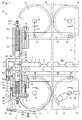
- Figure 1 is a schematic side view of an inventive Device 10 shown.
- Means e.g. According to EP-A-399 948, a packaging tube 1 supplied, the products at regular intervals 2 contains.
- the device 10 is used between the products 2
- Cross sealing seams 3 are formed in the central plane 4 of the hose 1 and cut in the middle.
- the individual packs 5 are transported away on a conveyor belt 6 in the conveying direction A.
- crank wheels 15-18 On two spaced upper and lower shafts 11, 12, 13, 14 a total of four crank wheels 15-18 are mounted, which are all driven synchronously by a drive motor 19 are.
- the upper wheels 15, 16 run counterclockwise lower clockwise.
- the gearbox connections between the engine 19 and wheels 15-18 are symbolic by chains 20 and one Gear train 21 indicated.
- With at least approximately uniform Radius 22 of shafts 11-14 carry wheels 15-18 axially parallel pins 23-26.
- an upper carrier 27 On the pin 23, 24 of the top Wheels 15, 16, an upper carrier 27 is rotatably supported such that he with the crank radii 22 and the connecting line between the waves 11, 12 at least approximately a parallelogram forms, so that with running wheels 15, 16, the carrier 27 in parallel circulates to itself.
- the Pin 25, 26 attached to a lower support 28.
- the top beam 27 and the lower support 28 carry at their rear end one crossbar 29, 30 each.
- the crossbars 29, 30 are on the Carriers 27, 28 guided in height and by Screws 31 adjustable. In a suitable position, the Crossbar 29, 30 also firmly connected to the beams 27, 28 be.
- a sealing jaw 37 and a counter jaw 38 guided in height.
- the jaws 37, 38 have parallel, flat sealing surface 39 or counter surface 40 and are biased by a plurality of springs 41 towards the central plane 4.
- One of the jaws 37, 38 has a not shown in the middle Knife to cut the hose 1 during the Sealing.
- the adjustment means can Bias of the springs 41 and thus the sealing pressure set will.
- springs 41 compressed air or another can also be used Fluid can be used as a pressing element.
- the support strips 48, 49 are by two in parallelogram levers 53 pivotally mounted with their center connected with which they have two parallelogram joints form.
- One of the two legs 52 is controlled by a control device 54 operated. In the example shown, this exists from a cam disk 55 rigidly connected to the wheel 17, on which a roller 56 at one end of a double-armed, pivoted lever 57 rolls.
- the other arm of the lever 57 has an elongated hole 58 in which the one joint 59 an articulated rod 60 is adjustably attached.
- the other joint 61 of the rod 60 is connected to one leg 52.
- Stop rollers 62 protrude from the jaws 37, 38 on both sides, which around axes parallel to the central plane 4 and perpendicular to Feed direction A are rotatably mounted on the jaws 37, 38.
- the strips 48, 49 are still something on it moved further against each other, so that the jaws 37, 38 with the Press the preload force of the springs 41 against the hose.
- the jaws 37, 38 are turned further into the bars 29, 30 pressed in until the dead center shown in Figure 1 is reached is.
- the jaws 37, 38 then extend again until the Nuts 44 come to rest on the beams 29, 30.
- the strips 48, 49 are controlled through the cam 55 again with increasing speed moved apart so that the jaws 37, 38 approximately on the velocity component perpendicular to the median plane 4 accelerated, which they when the nut 44 to have.
- the strips 48, 49 can also be controlled by a servo motor 65, which by a control device, not shown, is program-controlled is, the output of a rotary encoder as a reference signal 66 is used with one of the wheels 18 or with the motor 19 is connected.
- a servo motor 65 which by a control device, not shown, is program-controlled is, the output of a rotary encoder as a reference signal 66 is used with one of the wheels 18 or with the motor 19 is connected.
- This variant is dash-dotted in Figure 1 indicated. It has the advantage that the course of movement of the Last 48, 49 can be easily adjusted by changing the program can.
- the bearings of the axes can be used as an additional setting option 11-14 are formed adjustable across the central plane 14.
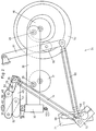
- FIG. 1 A variant of the control device 54 is shown in FIG.
- the cam disk 55 is here on one of the wheels 18 attached to one side of the machine.
- the link rod 60 is actuated a lever 71.
- the lever 71 is rotatably seated on one Shaft 72, which runs across the machine width. He has that Elongated hole 58 in which the hinge 59 is adjustably fastened is.
- the levers 73 are each with a joint rod 74 a further lever 75 connected to the Pivot axis 76 of a parallelogram lever 53 connected is.
- the levers 53 are directly connected to the support strips 48, 49 connected to a parallelogram linkage.
Landscapes
- Engineering & Computer Science (AREA)
- Mechanical Engineering (AREA)
- Package Closures (AREA)
- Containers And Plastic Fillers For Packaging (AREA)
- Lining Or Joining Of Plastics Or The Like (AREA)
Abstract
Description
- Figur 1
- eine schematische Seitenansicht einer Quersiegelvorrichtung, und
- Figur 2
- einen Teil einer Variante der Vorrichtung nach Figur 1.
Claims (10)
- Quersiegelvorrichtung zum Versiegeln eines Verpackungsschlauches (1), insbesondere für eine Schlauchbeutel-Verpackungsmaschine, umfassendzwei auf gegenüberliegenden Seiten einer Mittelebene (4) des Verpackungsschlauches (1) angeordnete Antriebseinheiten (15-21), welche einen ersten und zweiten Halter (27-30) umlaufend synchron und gegenläufig antreiben,eine im ersten Halter (27, 29) verschiebbar geführte und durch ein erstes Anpresselement (41) gegen einen ersten Anschlag (44) vorbelastete Siegelbacke (37), von der ein erstes Anschlagelement (62) absteht,eine im zweiten Halter (28, 30) verschiebbar geführte und durch ein zweites Anpresselement (41) gegen einen zweiten Anschlag (44) vorbelastete Gegenbacke (38), von der ein zweites Anschlagelement (62) absteht,zwei bewegliche Auflageelemente (48, 49) mit Auflageflächen (50, 51),eine Steuereinrichtung (54), um die Auflageelemente (48, 49) derart zu bewegen, dass das erste und zweite Anschlagelement (62) auf die zugehörige Auflagefläche (50, 51) aufläuft, bevor die Siegelbacke (37) und die Gegenbacke (38) zur pressenden Anlage auf den Schlauch (1) auftreffen, und dass die beiden Auflageelemente (48, 49) anschliessend gegeneinander bewegt werden, um die Bewegungskomponenten senkrecht zur Mittelebene der Siegelbacke (37) und der Gegenbacke (38) geführt zu verzögern.
- Vorrichtung nach Anspruch 1, wobei die Steuerelemente (54) derart ausgebildet sind, dass die Auflageelemente (48, 49) zur Anlage der Auflageflächen (50, 51) an das erste und zweite Anschlagelement (62) bewegt werden, bevor die Siegelbacke (37) von der Gegenbacke (38) abhebt, und dass die Siegelbacke (37) und Gegenbacke (38) auf eine zunehmend höhere Geschwindigkeit quer zur Mittelebene (4) beschleunigt werden.
- Vorrichtung nach Anspruch 1 oder 2, wobei die Antriebseinheiten (15-21) derart ausgebildet sind, dass die Siegelseite (39) der Siegelbacke (37) immer gegen die Gegenseite (40) der Gegenbacke (38) orientiert ist.
- Vorrichtung nach Anspruch 3, wobei der erste und zweite Halter (27, 28) an je zwei umlaufenden, synchron angetriebenen Kurbeln (15-18) mit annähernd gleich langen Kurbelradien (22) drehbar gelagert ist.
- Vorrichtung nach Anspruch 4, wobei die Länge der Auflageflächen (50, 51) mindestens 0,05 des Kurbelradius (22) beträgt und die Auflageflächen (50, 51) vorzugsweise eben sind.
- Vorrichtung nach einem der Ansprüche 1-5, wobei die beiden Anschlagelemente (62) als von der Siegelbacke (37) bzw. der Gegenbacke (38) seitlich abstehende, um Achsen parallel zur Mittelebene (4) drehbar gelagerte Rollen ausgebildet sind.
- Vorrichtung nach einem der Ansprüche 1-6, wobei jedes Auflageelement (48, 49) ein Glied je eines Parallelogrammgelenks (48, 49, 53) ist, von dem je ein Schenkel mit der Steuereinrichtung (54) antriebsverbunden ist.
- Vorrichtung nach einem der Ansprüche 1-7, wobei das Rotationszentrum der Siegelbacke (37) und der Gegenbacke (38) quer zur Mittelebene (4) einstellbar ist.
- Vorrichtung nach einem der Ansprüche 1-8, wobei die Steuereinrichtung (54) Einstellmittel (58, 59) aufweist.
- Vorrichtung nach einem der Ansprüche 1-9, wobei die Anschläge (44) und die Vorspannung der Siegelbacke (37) und der Gegenbacke (38) einstellbar sind.
Applications Claiming Priority (3)
| Application Number | Priority Date | Filing Date | Title |
|---|---|---|---|
| CH369694 | 1994-12-06 | ||
| CH3696/94 | 1994-12-06 | ||
| PCT/CH1995/000285 WO1996017720A1 (de) | 1994-12-06 | 1995-12-01 | Quersiegelvorrichtung für eine schlauchbeutel-verpackungsmaschine |
Publications (2)
| Publication Number | Publication Date |
|---|---|
| EP0796168A1 EP0796168A1 (de) | 1997-09-24 |
| EP0796168B1 true EP0796168B1 (de) | 1998-05-20 |
Family
ID=4261572
Family Applications (1)
| Application Number | Title | Priority Date | Filing Date |
|---|---|---|---|
| EP95936928A Expired - Lifetime EP0796168B1 (de) | 1994-12-06 | 1995-12-01 | Quersiegelvorrichtung für eine schlauchbeutel-verpackungsmaschine |
Country Status (7)
| Country | Link |
|---|---|
| US (1) | US5771660A (de) |
| EP (1) | EP0796168B1 (de) |
| JP (1) | JPH10509936A (de) |
| CN (1) | CN1064306C (de) |
| AU (1) | AU3921395A (de) |
| DE (1) | DE59502284D1 (de) |
| WO (1) | WO1996017720A1 (de) |
Cited By (1)
| Publication number | Priority date | Publication date | Assignee | Title |
|---|---|---|---|---|
| DE102010060818A1 (de) | 2009-12-17 | 2011-06-22 | inno-tech Verpackungsmaschinen GmbH, 35415 | Verpackungsmaschine mit zwei Quersiegelbacken zum Versiegeln einer Verpackung |
Families Citing this family (19)
| Publication number | Priority date | Publication date | Assignee | Title |
|---|---|---|---|---|
| US6178719B1 (en) * | 1997-11-03 | 2001-01-30 | Tetra Pak Hoyer A/S | Cross joining and/or cross cutting device in a packaging machine of the flow packing type |
| EP0945349B1 (de) | 1998-03-27 | 2004-01-02 | SIG Pack Systems AG | Vorrichtung zum Querschweissen und Trennen eines Verpackungsschlauches aus einer Thermoplastfolie, insbesondere für Schlauchbeutel-Verpackungsmachinen |
| US6138442A (en) * | 1998-10-13 | 2000-10-31 | Kliklok Corporation | Packaging machine with continuous sealing jaw movement |
| US6272815B1 (en) | 1998-11-03 | 2001-08-14 | Klockner-Bartelt, Inc. | Servo-controlled pouch making apparatus |
| JP2000219214A (ja) | 1999-01-29 | 2000-08-08 | Sig Pack Syst Ag | 特に包装装置内において包装用フィルムを封着するためのフィルム封着装置 |
| US6876896B1 (en) | 1999-04-26 | 2005-04-05 | Ab Tetrapak | Variable motion system and method |
| DE50103569D1 (de) | 2000-01-27 | 2004-10-21 | Sig Pack Systems Ag Beringen | Vorrichtung zum versiegeln eines verpackungsschlauches |
| US6962033B2 (en) * | 2000-12-28 | 2005-11-08 | Belco Packaging Systems, Inc. | Automatic high speed wrapping machine |
| JP5235636B2 (ja) * | 2008-12-09 | 2013-07-10 | 四国化工機株式会社 | 容器頂部シール装置 |
| US8087220B2 (en) | 2009-04-21 | 2012-01-03 | Extreme Packaging Machinery, Inc. | Film sealing and wrapping machine with rotary cut and seal jaw |
| BRPI1001928A2 (pt) * | 2010-06-21 | 2013-12-24 | Kraft Foods Global Brands Llc | Aparelho e métodos para enrolar produtos alimentícios |
| EP2720951B1 (de) * | 2011-06-15 | 2018-09-12 | Tetra Laval Holdings & Finance SA | Aufhängung für eine schweissbacke und verfahren zur kalibrierung von schweissbacken |
| CA2945522A1 (en) * | 2014-04-15 | 2015-12-23 | The Skylife Company, Inc. | Remote packing system |
| WO2017042136A1 (en) | 2015-09-10 | 2017-03-16 | Tetra Laval Holdings & Finance S.A. | A pressure jaw assembly and a sealing jaw arrangement |
| EP3408069A1 (de) * | 2016-01-25 | 2018-12-05 | Tetra Laval Holdings & Finance S.A. | Dichtungsvorrichtung und verfahren zur wärmeversiegelung eines verpackungsmaterials und eine füllmaschine |
| IT201600090075A1 (it) * | 2016-09-06 | 2018-03-06 | Ima Spa | Dispositivo di unione di sacchetti filtro con prodotti da infusione. |
| JP6380594B1 (ja) * | 2017-03-31 | 2018-08-29 | 富士電機株式会社 | 制御装置、間欠型包装機および間欠型包装機の制御方法 |
| EP4741295A2 (de) | 2024-11-12 | 2026-05-13 | Sasib S.p.A. | Verfahren und vorrichtung zur herstellung von beuteln mit einer jeweiligen menge eines losen materials, insbesondere snus |
| EP4741297A2 (de) | 2024-11-12 | 2026-05-13 | Sasib S.p.A. | Verfahren und maschine zur herstellung von beuteln mit einer jeweiligen menge eines losen materials, insbesondere sinus |
Family Cites Families (19)
| Publication number | Priority date | Publication date | Assignee | Title |
|---|---|---|---|---|
| US2467879A (en) * | 1945-05-17 | 1949-04-19 | Milprint Inc | Bagmaking machine |
| DE1114630B (de) * | 1958-05-17 | 1961-10-05 | Herfurth Gmbh | Verfahren und Vorrichtung zum Verschweissen thermoplastischer Kunststoffe oder damit beschichteter Materialien |
| DE2614990A1 (de) * | 1976-04-07 | 1977-10-20 | Bosch Gmbh Robert | Vorrichtung zum quersiegeln und trennen eines einwickelschlauchs in einer kontinuierlich arbeitenden einwickelmaschine |
| US4141196A (en) * | 1977-10-11 | 1979-02-27 | Oliver Machinery Company | Seal wrapping machine |
| DE2900695C2 (de) * | 1979-01-10 | 1985-06-20 | Tetra Pak International AB, Lund | Maschine zum Herstellen von Packungen |
| US4283539A (en) * | 1979-12-18 | 1981-08-11 | Pfizer Inc. | Isoquinoline acetic acids |
| US4433527A (en) * | 1981-08-19 | 1984-02-28 | E. I. Du Pont De Nemours And Company | Heat sealing film cut-off device |
| DE3367190D1 (en) * | 1982-12-07 | 1986-12-04 | Claus K Pfankuch | Device for wrapping articles with a plastic sheet or the like |
| DE3732033A1 (de) * | 1987-09-23 | 1989-04-13 | Rovema Gmbh | Siegelvorrichtung |
| JPH0283204U (de) * | 1988-12-16 | 1990-06-27 | ||
| EP0399948B1 (de) * | 1989-05-24 | 1994-11-02 | SIG Schweizerische Industrie-Gesellschaft | Verfahren und Vorrichtung zum kontinuierlichen Herstellen von Packungen |
| JP3287474B2 (ja) * | 1991-09-13 | 2002-06-04 | 株式会社イシダ | 縦型ピロー包装機 |
| JP2540117B2 (ja) * | 1990-07-31 | 1996-10-02 | 雅夫 福田 | 包装機 |
| US5237800A (en) * | 1991-03-29 | 1993-08-24 | Omori Machinery Co., Ltd. | Shrink-wrapping method and apparatus |
| JPH0648422A (ja) * | 1991-06-11 | 1994-02-22 | Ibaraki Seiki Kk | 包装材料加熱シール装置 |
| US5371999A (en) * | 1991-11-12 | 1994-12-13 | Inter Pak Equipment Corporation | Shrink film wrapping machine |
| US5271210A (en) * | 1993-03-12 | 1993-12-21 | Ossid Corporation | Packaging machine with reciprocating conveyor |
| CA2170305C (en) * | 1995-08-01 | 2000-12-12 | Norbert P. Keopple | Modular cutting head apparatus for high speed wrapping machine |
| US5537804A (en) * | 1995-09-11 | 1996-07-23 | Ossid Corporation | Film sealing apparatus and method |
-
1995
- 1995-12-01 EP EP95936928A patent/EP0796168B1/de not_active Expired - Lifetime
- 1995-12-01 JP JP8517220A patent/JPH10509936A/ja not_active Ceased
- 1995-12-01 CN CN95196593A patent/CN1064306C/zh not_active Expired - Fee Related
- 1995-12-01 WO PCT/CH1995/000285 patent/WO1996017720A1/de not_active Ceased
- 1995-12-01 DE DE59502284T patent/DE59502284D1/de not_active Expired - Lifetime
- 1995-12-01 US US08/817,674 patent/US5771660A/en not_active Expired - Lifetime
- 1995-12-01 AU AU39213/95A patent/AU3921395A/en not_active Abandoned
Cited By (2)
| Publication number | Priority date | Publication date | Assignee | Title |
|---|---|---|---|---|
| DE102010060818A1 (de) | 2009-12-17 | 2011-06-22 | inno-tech Verpackungsmaschinen GmbH, 35415 | Verpackungsmaschine mit zwei Quersiegelbacken zum Versiegeln einer Verpackung |
| DE102010060818B4 (de) | 2009-12-17 | 2018-05-17 | Inno-Tech Verpackungsmaschinen Gmbh | Verpackungsmaschine mit zwei Quersiegelbacken zum Versiegeln einer Verpackung |
Also Published As
| Publication number | Publication date |
|---|---|
| EP0796168A1 (de) | 1997-09-24 |
| WO1996017720A1 (de) | 1996-06-13 |
| CN1064306C (zh) | 2001-04-11 |
| DE59502284D1 (de) | 1998-06-25 |
| JPH10509936A (ja) | 1998-09-29 |
| AU3921395A (en) | 1996-06-26 |
| US5771660A (en) | 1998-06-30 |
| CN1168650A (zh) | 1997-12-24 |
Similar Documents
| Publication | Publication Date | Title |
|---|---|---|
| EP0796168A1 (de) | Quersiegelvorrichtung für eine schlauchbeutel-verpackungsmaschine | |
| DE4100769C2 (de) | Vorrichtung zum Fördern von Produkten in einer Verpackungsmaschine | |
| DE68903016T2 (de) | Vorrichtung zum Verschliessen von Behältern mittels einer versiegelbaren Folie. | |
| DE69725712T2 (de) | Verpackungsmaschine zum kontinuierlichen Herstellen von versiegelten Verpackungen fliessfähiger Nahrungsmittel aus schlauchförmigem Verpackungsmaterial | |
| DE19518583C2 (de) | Schneidmaschine zum Zerschneiden von Produktlaiben | |
| DE69213429T2 (de) | Vorrichtung zum Zuführen von Packungen aus einer Verpackungsbahn zu einem Behälter | |
| EP0569335B1 (de) | Vorrichtung zum Füllen von flexiblen Beuteln | |
| DE1479627B2 (de) | Maschine zum bearbeiten vorzugsweise schweissen undtrennen einer doppelten bahn insbesondere einer thermoplastischen folie beim herstellen von saecken | |
| DE1288509B (de) | Vorrichtung zum Ordnen von auf einem Foerderband in willkuerlicher Anordnung angelieferten Artikeln in gleichem Abstand | |
| DE2407358A1 (de) | Behaelter-verschliessvorrichtung | |
| DD273611A1 (de) | Vorrichtung zum uebergeben von bonbons | |
| DE3702954A1 (de) | Gruppiereinrichtung zur bildung von behaeltergruppen | |
| EP1466829B1 (de) | Rotierende Füllmaschine mit Verschliessvorrichtung | |
| EP0247598B1 (de) | Fördervorrichtung für Werkstücke | |
| DE1549171C3 (de) | Transportvorrichtung tür Warenpackungen | |
| EP3269539A1 (de) | Vorrichtung zum öffnen eines endbereichs eines schlauchförmigen sackkörpers | |
| DE2446364C3 (de) | Vorrichtung zum Transport von Bogen | |
| DE2414943B2 (de) | Vorrichtung zum Transportieren und Tragen von zu verpackenden Einzelstücken | |
| CH637084A5 (en) | Conveying device with a conveyor forming a conveying plane and lateral guides | |
| DE2159146A1 (de) | Verfahren zum verpacken von artikeln und verpackungsmaschine zur ausuebung des verfahrens | |
| DE2052960A1 (de) | Vorrichtung zum Dirigieren von laufbandbefordertem Gut zu verschiedenen Fördervorrichtungen oder dergleichen | |
| CH385715A (de) | Verpackungsmaschine | |
| DE4010506C2 (de) | Maschine zum dichten Verschließen von Verpackungen | |
| DE1270478B (de) | Einrichtung zum Quersiegeln und Trennen eines Einwicklerschlauches an einer kontinuierlich arbeitenden Einwickelmaschine | |
| DE69301235T2 (de) | Vorrichtung zum verpacken von gegenständen in folie |
Legal Events
| Date | Code | Title | Description |
|---|---|---|---|
| PUAI | Public reference made under article 153(3) epc to a published international application that has entered the european phase |
Free format text: ORIGINAL CODE: 0009012 |
|
| 17P | Request for examination filed |
Effective date: 19970703 |
|
| AK | Designated contracting states |
Kind code of ref document: A1 Designated state(s): CH DE GB IT LI NL |
|
| GRAG | Despatch of communication of intention to grant |
Free format text: ORIGINAL CODE: EPIDOS AGRA |
|
| 17Q | First examination report despatched |
Effective date: 19971001 |
|
| GRAG | Despatch of communication of intention to grant |
Free format text: ORIGINAL CODE: EPIDOS AGRA |
|
| GRAH | Despatch of communication of intention to grant a patent |
Free format text: ORIGINAL CODE: EPIDOS IGRA |
|
| GRAH | Despatch of communication of intention to grant a patent |
Free format text: ORIGINAL CODE: EPIDOS IGRA |
|
| GRAA | (expected) grant |
Free format text: ORIGINAL CODE: 0009210 |
|
| AK | Designated contracting states |
Kind code of ref document: B1 Designated state(s): CH DE GB IT LI NL |
|
| REG | Reference to a national code |
Ref country code: CH Ref legal event code: EP |
|
| REF | Corresponds to: |
Ref document number: 59502284 Country of ref document: DE Date of ref document: 19980625 |
|
| RAP2 | Party data changed (patent owner data changed or rights of a patent transferred) |
Owner name: SIG PACK SYTEMS AG |
|
| REG | Reference to a national code |
Ref country code: CH Ref legal event code: NV Representative=s name: ISLER & PEDRAZZINI AG |
|
| ITF | It: translation for a ep patent filed | ||
| GBT | Gb: translation of ep patent filed (gb section 77(6)(a)/1977) |
Effective date: 19980722 |
|
| RAP4 | Party data changed (patent owner data changed or rights of a patent transferred) |
Owner name: SIG PACK SYSTEMS AG |
|
| NLT2 | Nl: modifications (of names), taken from the european patent patent bulletin |
Owner name: SIG PACK SYTEMS AG |
|
| PLBE | No opposition filed within time limit |
Free format text: ORIGINAL CODE: 0009261 |
|
| STAA | Information on the status of an ep patent application or granted ep patent |
Free format text: STATUS: NO OPPOSITION FILED WITHIN TIME LIMIT |
|
| 26N | No opposition filed | ||
| REG | Reference to a national code |
Ref country code: GB Ref legal event code: IF02 |
|
| REG | Reference to a national code |
Ref country code: CH Ref legal event code: PCAR Free format text: ISLER & PEDRAZZINI AG;POSTFACH 1772;8027 ZUERICH (CH) |
|
| PGFP | Annual fee paid to national office [announced via postgrant information from national office to epo] |
Ref country code: GB Payment date: 20091221 Year of fee payment: 15 |
|
| GBPC | Gb: european patent ceased through non-payment of renewal fee |
Effective date: 20101201 |
|
| PG25 | Lapsed in a contracting state [announced via postgrant information from national office to epo] |
Ref country code: GB Free format text: LAPSE BECAUSE OF NON-PAYMENT OF DUE FEES Effective date: 20101201 |
|
| PGFP | Annual fee paid to national office [announced via postgrant information from national office to epo] |
Ref country code: NL Payment date: 20111221 Year of fee payment: 17 |
|
| PGFP | Annual fee paid to national office [announced via postgrant information from national office to epo] |
Ref country code: CH Payment date: 20121218 Year of fee payment: 18 |
|
| REG | Reference to a national code |
Ref country code: NL Ref legal event code: V1 Effective date: 20130701 |
|
| PG25 | Lapsed in a contracting state [announced via postgrant information from national office to epo] |
Ref country code: NL Free format text: LAPSE BECAUSE OF NON-PAYMENT OF DUE FEES Effective date: 20130701 |
|
| PGFP | Annual fee paid to national office [announced via postgrant information from national office to epo] |
Ref country code: DE Payment date: 20140221 Year of fee payment: 19 |
|
| REG | Reference to a national code |
Ref country code: CH Ref legal event code: PL |
|
| PG25 | Lapsed in a contracting state [announced via postgrant information from national office to epo] |
Ref country code: LI Free format text: LAPSE BECAUSE OF NON-PAYMENT OF DUE FEES Effective date: 20131231 Ref country code: CH Free format text: LAPSE BECAUSE OF NON-PAYMENT OF DUE FEES Effective date: 20131231 |
|
| PGFP | Annual fee paid to national office [announced via postgrant information from national office to epo] |
Ref country code: IT Payment date: 20141218 Year of fee payment: 20 |
|
| REG | Reference to a national code |
Ref country code: DE Ref legal event code: R119 Ref document number: 59502284 Country of ref document: DE |
|
| REG | Reference to a national code |
Ref country code: DE Ref legal event code: R082 Ref document number: 59502284 Country of ref document: DE Representative=s name: HOEGER, STELLRECHT & PARTNER PATENTANWAELTE MB, DE |
|
| PG25 | Lapsed in a contracting state [announced via postgrant information from national office to epo] |
Ref country code: DE Free format text: LAPSE BECAUSE OF NON-PAYMENT OF DUE FEES Effective date: 20150701 |