EP0796190B1 - Servomoteur pneumatique d'assistance au freinage - Google Patents
Servomoteur pneumatique d'assistance au freinage Download PDFInfo
- Publication number
- EP0796190B1 EP0796190B1 EP95934204A EP95934204A EP0796190B1 EP 0796190 B1 EP0796190 B1 EP 0796190B1 EP 95934204 A EP95934204 A EP 95934204A EP 95934204 A EP95934204 A EP 95934204A EP 0796190 B1 EP0796190 B1 EP 0796190B1
- Authority
- EP
- European Patent Office
- Prior art keywords
- bolt
- chamber
- volume
- wall
- pneumatic
- Prior art date
- Legal status (The legal status is an assumption and is not a legal conclusion. Google has not performed a legal analysis and makes no representation as to the accuracy of the status listed.)
- Expired - Lifetime
Links
- 230000005540 biological transmission Effects 0.000 description 6
- 239000011324 bead Substances 0.000 description 5
- 239000012528 membrane Substances 0.000 description 5
- 239000000463 material Substances 0.000 description 3
- 230000002093 peripheral effect Effects 0.000 description 3
- 230000006835 compression Effects 0.000 description 2
- 238000007906 compression Methods 0.000 description 2
- 229920001971 elastomer Polymers 0.000 description 2
- 230000035882 stress Effects 0.000 description 2
- 230000000694 effects Effects 0.000 description 1
- 239000000806 elastomer Substances 0.000 description 1
- 230000006355 external stress Effects 0.000 description 1
- 238000012986 modification Methods 0.000 description 1
- 230000004048 modification Effects 0.000 description 1
- 238000005096 rolling process Methods 0.000 description 1
Images

Classifications
-
- B—PERFORMING OPERATIONS; TRANSPORTING
- B60—VEHICLES IN GENERAL
- B60T—VEHICLE BRAKE CONTROL SYSTEMS OR PARTS THEREOF; BRAKE CONTROL SYSTEMS OR PARTS THEREOF, IN GENERAL; ARRANGEMENT OF BRAKING ELEMENTS ON VEHICLES IN GENERAL; PORTABLE DEVICES FOR PREVENTING UNWANTED MOVEMENT OF VEHICLES; VEHICLE MODIFICATIONS TO FACILITATE COOLING OF BRAKES
- B60T13/00—Transmitting braking action from initiating means to ultimate brake actuator with power assistance or drive; Brake systems incorporating such transmitting means, e.g. air-pressure brake systems
- B60T13/10—Transmitting braking action from initiating means to ultimate brake actuator with power assistance or drive; Brake systems incorporating such transmitting means, e.g. air-pressure brake systems with fluid assistance, drive, or release
- B60T13/24—Transmitting braking action from initiating means to ultimate brake actuator with power assistance or drive; Brake systems incorporating such transmitting means, e.g. air-pressure brake systems with fluid assistance, drive, or release the fluid being gaseous
- B60T13/46—Vacuum systems
- B60T13/52—Vacuum systems indirect, i.e. vacuum booster units
- B60T13/569—Vacuum systems indirect, i.e. vacuum booster units characterised by piston details, e.g. construction, mounting of diaphragm
-
- B—PERFORMING OPERATIONS; TRANSPORTING
- B60—VEHICLES IN GENERAL
- B60T—VEHICLE BRAKE CONTROL SYSTEMS OR PARTS THEREOF; BRAKE CONTROL SYSTEMS OR PARTS THEREOF, IN GENERAL; ARRANGEMENT OF BRAKING ELEMENTS ON VEHICLES IN GENERAL; PORTABLE DEVICES FOR PREVENTING UNWANTED MOVEMENT OF VEHICLES; VEHICLE MODIFICATIONS TO FACILITATE COOLING OF BRAKES
- B60T13/00—Transmitting braking action from initiating means to ultimate brake actuator with power assistance or drive; Brake systems incorporating such transmitting means, e.g. air-pressure brake systems
- B60T13/10—Transmitting braking action from initiating means to ultimate brake actuator with power assistance or drive; Brake systems incorporating such transmitting means, e.g. air-pressure brake systems with fluid assistance, drive, or release
- B60T13/24—Transmitting braking action from initiating means to ultimate brake actuator with power assistance or drive; Brake systems incorporating such transmitting means, e.g. air-pressure brake systems with fluid assistance, drive, or release the fluid being gaseous
- B60T13/46—Vacuum systems
- B60T13/52—Vacuum systems indirect, i.e. vacuum booster units
- B60T13/567—Vacuum systems indirect, i.e. vacuum booster units characterised by constructional features of the casing or by its strengthening or mounting arrangements
- B60T13/5675—Supportstruts
Definitions
- the present invention relates to pneumatic actuators, of the type which are used to provide brake assist for motor vehicles.
- Such servomotors are well known and commonly used in the art automobile. They conventionally comprise an envelope fixed by its rear wall to the bulkhead separating the engine compartment from the passenger compartment, so that they can be actuated by a brake pedal located in the passenger compartment and actuating the primary piston of a master cylinder located in the engine compartment and connected by a hydraulic circuit to the vehicle brakes, the master cylinder being fixed on the front wall of the casing of the booster.
- the envelope is separated in a leaktight manner by a movable wall structure in a front chamber permanently connected to a low pressure source, and a rear chamber selectively connected to the front chamber or to a high pressure source by means of three-way valve, actuated by a control rod connected to the brake pedal, and which is likely to rest, via the front face of a diver, on the rear face a push rod secured to a reaction disc and actuating the primary piston of the master cylinder.
- a corresponding servomotor in the preamble to the main claim, and in which an auxiliary unit is integral with the movable wall and projects into the front chamber.
- An auxiliary piston internally divides sealingly the auxiliary housing in a front volume and a rear volume.
- the piston auxiliary is mounted fixed relative to the enclosure, and the front volume is permanently connected with the rear chamber and the rear volume is permanently connected with the front chamber.
- the object of the present invention is therefore to propose a booster comprising a additional chamber, and whose rigidity in the axial direction is increased, so as to the stroke of the brake pedal is constant.
- the booster of the type mentioned above further comprises at least one element for transmitting the reaction force generated by actuation of a master cylinder on a mounting flange thereof at the front of the pneumatic actuator, the reaction force transmission element being fixed on the flange fixing and crossing the envelope right through parallel to the axis of symmetry of the servomotor and integral with the front and rear walls of the enclosure, and the transmission element reaction force being a tie passing tightly through the front face of the housing auxiliary.
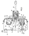
- the Figures show a pneumatic brake booster provided to be placed in the usual way between the brake pedal of a vehicle and the master cylinder controlling the hydraulic brake system of this vehicle.
- a pneumatic brake booster provided to be placed in the usual way between the brake pedal of a vehicle and the master cylinder controlling the hydraulic brake system of this vehicle.
- the booster shown in the Figures comprises an outer casing 10 in shell shape, having a symmetry of revolution around an axis XX '.
- a movable wall structure 12 sealingly delimits inside the envelope 10 a front chamber 14, permanently connected by a non-return valve 15 to a source of depression and a rear chamber 16.
- the movable wall 12 is associated with a membrane flexible drop-down elastomer 18 whose inner peripheral edge is received so waterproof thanks to an internal bead in a hollow assistance piston 20 arranged along the axis X-X 'of the actuator, and the outer peripheral edge of which is tightly fixed to the outer casing 10.
- the hollow piston 20 extends backwards in the form of a tubular part 22 which tightly crosses the rear wall of the casing 10.
- a compression spring 24 interposed between the piston 20 and the front wall of the casing 10 normally holds the piston 20 in the rear rest position illustrated in the Figure, in which the rear chamber 16 has its minimum volume and the front chamber 14 its maximum volume.
- the piston 20 In the central part of the movable wall located in front of the rear tubular part 22, the piston 20 has a bore in which a plunger 26 is received slidingly.
- the plunger 26 controls the operation of a three-way valve 30, selectively placing the rear chamber 16 in communication with the front chamber 14 or with a high pressure source, such as for example the atmosphere present at the rear of the tubular part 22.
- An annular auxiliary unit 32 is integral with the movable wall 12 and projects into the front chamber 14.
- An annular auxiliary piston 34 sealingly delimits inside the housing 32 a front volume 36 and a rear volume 38. The tightness is ensured by a flexible elastomeric rolling membrane 40, the outer peripheral edge of which is fixed tightly on the housing 32.
- a force transmitting element reaction between the front wall 42 and the rear wall 44 of the casing 10 of the booster.
- this force transmission element is consisting of a tie rod, integral with the annular auxiliary piston 34, or formed in one piece with him as we have represented.
- the tie rod 50 consists for example of a tube, the two of which ends are tapped.
- the first part of a stud 52 In the rear end is screwed the first part of a stud 52, formed with a central bulge 54 disposed inside the envelope 10 and in abutment on the internal face of the rear wall 44, the second part 56 of the stud 52 passing through a opening of the wall 44, the edges of which are crimped onto the stud.
- a seal may advantageously be inserted between the bulge 54 and the wall 44.
- first part of a second stud 58 is screwed into the front end of the pulling 50, the second part 60 of the stud 58 sealingly crossing an opening in the front wall 42, for example using a tubular rubber plug 62 as described above represented.
- the plug 62 is also applied in a sealed manner to the tie rod 50.
- annular groove 64 is formed around the tie rod 50 to receive sealingly a bead of the membrane 40.
- the membrane 18 of the structure of movable wall 12 is formed with an opening whose edges form a bead 66 fixed with tightly around the rear end of tie rod 50.
- Axial grooves 68 are formed in the thread of the rear end of the tie rod 50, over a length greater than the length of the first part of the stud 52, and radial openings 70 are made in the rear end of the tie rod 50, behind the fixing the bead 66, and open into the grooves 68, to communicate the rear chamber 16 of the booster with the volume 72 inside the tubular tie rod 50.
- Radial openings 74 are also made in the tubular tie rod 50, in before the groove 64 for fixing the bead of the membrane 40, to communicate the volume 72 with the front volume 36 of the auxiliary box 32. Openings 76 are made in the wall of the auxiliary box 32, to communicate the front chamber 14 of the servomotor with rear volume 38 of auxiliary unit 32
- a lip seal 78 is disposed in an opening formed at the front. of the auxiliary box 32, to ensure a sliding seal between this box and the tie rod 50.
- a nut 79 may advantageously be screwed onto the second part 60 of the stud 58, of a part to keep the two parts 42 and 44 forming the envelope 10 assembled and so facilitate handling and storage of the actuator, and secondly to determine so specifies the axial distance at rest between the front 42 and rear 44 faces of the booster.
- the actuator thus assembled is fixed to the bulkhead (not shown) separating the engine compartment of the passenger compartment vehicle, by means of a nut screwed by the passenger compartment to the second part 56 of the stud 52 passing through an opening of the deck.
- a master cylinder (no shown) is fixed to the front of the actuator by means of a nut screwed onto the second part 60 of the stud 58 passing through an opening formed in a fixing flange of the master cylinder.
- the reaction disc 80 is integral with a push rod 82, which actuates the piston master cylinder primary, which increases the hydraulic pressure in the braking to which it is connected.
- the actuation of the master cylinder generates a reaction force on the mounting flange.
- This flange being fixed on the stud 58, itself integral of the tie rod 50, fixed by the stud 52 on the bulkhead of the vehicle, the reaction force created by the actuation of the master cylinder is thus transmitted directly to the vehicle bulkhead by the pulling 50, without being transmitted by the casing 10 of the booster.
- Figure 2 a variant of the embodiment which has just been described.
- the same elements as those in Figure 1 are assigned the same reference signs, and they will not be described again in detail.
- the pulling is compressible in the axial direction, so that it can transmit the force of reaction of the master cylinder to the deck, without transmitting forces on this deck in the event of vehicle collision, thus increasing the passive safety of the vehicle equipped with such a servo motor.
- the tie rod 100 shown in Figure 2 consists of a cable 102 at the ends which are crimped with end pieces 104 and 106.
- Each piece 104 and 106 is provided, at its end, with a threaded part 108 and 110 respectively, passing through an opening in the wall 42 and 44.
- the end piece 106 is formed with a median bulge 112, disposed at inside the envelope 10 and in abutment on the internal face of the rear wall 44, the edge of the opening in the wall 44 being crimped on the end piece 106.
- a seal may advantageously be inserted between the bulge 112 and the wall 44.
- the annular auxiliary piston 34 is integral with a tube 114, surrounding the tie rod 100, and sealingly passing through the auxiliary housing 32, by means of a lip seal disposed in a opening formed at the front of this housing 32.
- the tube 114 is provided with openings 74 and 70 as in the previous embodiment, to communicate the rear chamber 16 of the servomotor with the front volume 36 of the auxiliary box 32.
- the plug tubular 62 seals the passage of the end piece 104 through the wall 42, and from the inside of the tube 114 relative to the front chamber 14 of the booster.
- the tube 114 has no other function than to seal the passage of the cable 102 through the front face of the auxiliary box 32, and to communicate the room rear 16 of the actuator with the front volume 36 of the auxiliary box, the transmission of the reaction force due to the actuation of the master cylinder being provided by the cable 102 of the pulling 100.
- the tube 114 can therefore be made of a relatively light material, such as a plastic material.
- the tube 114 may break, so that none rearward force is transmitted from the front wall 42 of the booster to the vehicle bulkhead. The consequences of a collision are therefore reduced for the driver of the vehicle.
- the compressible tie rod is of the telescopic type, and consists for example of two tubes threaded one inside the other.
- the tie rod 50 of Figure 1 can thus consist of two tubes, a rear tube fixed to the rear wall 44 of the booster and secured to the annular piston auxiliary 34, and a front tube fixed to the front wall 42 of the actuator, the front tube having an external radial shoulder cooperating with an internal radial shoulder of the tube rear to ensure the transmission of reaction forces, a seal being arranged between the two tubes to isolate the interior space of the tie rod from the front chamber of the servomotor, the front tube being able to slide in the rear tube under the effect of a external stress following a collision, so as to avoid any transmission of forces from the front wall of the actuator to the vehicle bulkhead.
Landscapes
- Engineering & Computer Science (AREA)
- Transportation (AREA)
- Mechanical Engineering (AREA)
- Braking Systems And Boosters (AREA)
Description
Claims (7)
- Servomoteur pneumatique d'assistance au freinage, comportant une enveloppe (10) possédant un axe de symétrie (X-X'), séparée de façon étanche par une structure de paroi mobile (12) en une chambre avant (14) reliée en permanence à une source de basse pression, et une chambre arrière (16) reliée sélectivement à la chambre avant (14) ou à une source de haute pression par un moyen de valve à trois voies (30) actionnée par une tige de commande (28) susceptible de s'appuyer, par l'intermédiaire de la face avant d'un plongeur (26), sur la face arrière d'une tige de poussée (82) solidaire d'un disque de réaction (80), un boítier auxiliaire (32) étant solidaire de la paroi mobile (12) et faisant saillie dans la chambre avant (14), un piston auxiliaire (34) divisant intérieurement de façon étanche le boítier auxiliaire (32) en un volume avant (36) et un volume arrière (38), le piston auxiliaire (34) étant monté fixe par rapport à l'enveloppe (10), le volume avant (36) étant relié en permanence avec la chambre arrière (16) et le volume arrière (38) étant relié en permanence avec la chambre avant (14), caractérisé en ce qu'il comporte en outre au moins un élément de transmission de force de réaction (50,100) engendrée par l'actionnement d'un maítre-cylindre sur une bride de fixation de celui-ci à l'avant du servomoteur pneumatique, l'élément de transmission de force de réaction (50,100) étant fixé sur la bride de fixation et traversant l'enveloppe (10) de part en part parallèlement à l'axe de symétrie (X-X') du servomoteur et solidaire des parois avant (42) et arrière (44) de l'enveloppe (10), et l'élément de transmission de force de réaction étant un tirant (50, 100) traversant de façon étanche la face avant du boítier auxiliaire (32).
- Servomoteur pneumatique selon la revendication 1, caractérisé en ce que le tirant (50) est solidaire du piston auxiliaire (34).
- Servomoteur pneumatique selon la revendication 2, caractérisé en ce que le tirant (50) est tubulaire sur au moins une partie de sa longueur, et comporte au moins une première ouverture (70) faisant communiquer l'espace intérieur (72) du tirant (50) avec la chambre arrière (16) et au moins une seconde ouverture (74) faisant communiquer l'espace intérieur (72) du tirant (50) avec le volume avant (36).
- Servomoteur pneumatique selon la revendication 1, caractérisé en ce que le tirant (100) est compressible suivant la direction axiale (X-X').
- Servomoteur pneumatique selon la revendication 4, caractérisé en ce que le tirant compressible (100) comporte sur au moins une partie de sa longueur un câble (102).
- Servomoteur pneumatique selon la revendication 5, caractérisé en ce que le câble (102) est disposé à l'intérieur d'un tube (114) traversant de façon étanche la face avant du boítier auxiliaire (32).
- Servomoteur pneumatique selon la revendication 4, caractérisé en ce que le tirant compressible comprend au moins deux tubes enfilés l'un dans l'autre pour constituer un tirant télescopique.
Applications Claiming Priority (3)
| Application Number | Priority Date | Filing Date | Title |
|---|---|---|---|
| FR9414811A FR2727921A1 (fr) | 1994-12-09 | 1994-12-09 | Servomoteur pneumatique d'assistance au freinage |
| FR9414811 | 1994-12-09 | ||
| PCT/FR1995/001330 WO1996017759A1 (fr) | 1994-12-09 | 1995-10-12 | Servomoteur pneumatique d'assistance au freinage |
Publications (2)
| Publication Number | Publication Date |
|---|---|
| EP0796190A1 EP0796190A1 (fr) | 1997-09-24 |
| EP0796190B1 true EP0796190B1 (fr) | 2000-03-29 |
Family
ID=9469629
Family Applications (1)
| Application Number | Title | Priority Date | Filing Date |
|---|---|---|---|
| EP95934204A Expired - Lifetime EP0796190B1 (fr) | 1994-12-09 | 1995-10-12 | Servomoteur pneumatique d'assistance au freinage |
Country Status (6)
| Country | Link |
|---|---|
| EP (1) | EP0796190B1 (fr) |
| JP (1) | JPH11503684A (fr) |
| DE (1) | DE69516014T2 (fr) |
| ES (1) | ES2143653T3 (fr) |
| FR (1) | FR2727921A1 (fr) |
| WO (1) | WO1996017759A1 (fr) |
Families Citing this family (4)
| Publication number | Priority date | Publication date | Assignee | Title |
|---|---|---|---|---|
| GB9519753D0 (en) * | 1995-09-28 | 1995-11-29 | Lucas Ind Plc | Improvements in pneumatically-operated boosters for vehicle braking systems |
| JP6350180B2 (ja) * | 2014-09-30 | 2018-07-04 | 株式会社アドヴィックス | 負圧式倍力装置 |
| DE102017203559A1 (de) * | 2017-03-06 | 2018-09-06 | Robert Bosch Gmbh | Elektromechanischer Bremskraftverstärker und Herstellungsverfahren für einen elektromechanischen Bremskraftverstärker |
| KR102410730B1 (ko) * | 2017-11-30 | 2022-06-20 | 현대모비스 주식회사 | 브레이크 부스터 |
Family Cites Families (4)
| Publication number | Priority date | Publication date | Assignee | Title |
|---|---|---|---|---|
| DE2830262A1 (de) * | 1978-07-10 | 1980-01-24 | Teves Gmbh Alfred | Bremskraftverstaerker fuer ein kraftfahrzeug |
| JP2739875B2 (ja) * | 1988-02-05 | 1998-04-15 | ルーカス・インダストリーズ・パブリック・リミテッド・カンパニー | 車両ブレーキ装置用空気圧倍力装置 |
| FR2646477B1 (fr) * | 1989-04-28 | 1991-07-05 | Bendix France | Servomoteur a depression |
| DE9005629U1 (de) * | 1990-05-17 | 1991-09-12 | Lucas Industries P.L.C., Birmingham, West Midlands | Pneumatischer Kraftverstärker für Fahrzeug-Bremsanlagen |
-
1994
- 1994-12-09 FR FR9414811A patent/FR2727921A1/fr active Granted
-
1995
- 1995-10-12 ES ES95934204T patent/ES2143653T3/es not_active Expired - Lifetime
- 1995-10-12 WO PCT/FR1995/001330 patent/WO1996017759A1/fr not_active Ceased
- 1995-10-12 JP JP8517351A patent/JPH11503684A/ja active Pending
- 1995-10-12 DE DE69516014T patent/DE69516014T2/de not_active Expired - Fee Related
- 1995-10-12 EP EP95934204A patent/EP0796190B1/fr not_active Expired - Lifetime
Also Published As
| Publication number | Publication date |
|---|---|
| EP0796190A1 (fr) | 1997-09-24 |
| JPH11503684A (ja) | 1999-03-30 |
| DE69516014D1 (de) | 2000-05-04 |
| DE69516014T2 (de) | 2000-09-14 |
| FR2727921A1 (fr) | 1996-06-14 |
| FR2727921B1 (fr) | 1997-02-14 |
| ES2143653T3 (es) | 2000-05-16 |
| WO1996017759A1 (fr) | 1996-06-13 |
Similar Documents
| Publication | Publication Date | Title |
|---|---|---|
| EP0331535B1 (fr) | Servomoteur d'assistance au freinage | |
| EP0939713B1 (fr) | Dispositif de freinage assiste a rapport d'assistance variable et hysteresis reduite | |
| EP0767747B1 (fr) | Ensemble d'un servomoteur pneumatique d'assistance au freinage et d'un maitre-cylindre | |
| EP0796190B1 (fr) | Servomoteur pneumatique d'assistance au freinage | |
| EP0779868B1 (fr) | Dispositif de freinage assiste a course masquee et a securite accrue | |
| EP0779870B1 (fr) | Servomoteur pneumatique d'assistance au freinage | |
| EP0514224B1 (fr) | Servomoteur pneumatique | |
| EP0514239A1 (fr) | Servomoteur pneumatique | |
| EP0939715B1 (fr) | Systeme de feinage assiste a reaction hydraulique amelioree | |
| EP0730538B1 (fr) | Dispositif de freinage assiste a course masquee et a gain garanti | |
| EP0614428B1 (fr) | Servomoteur d'assistance au freinage | |
| EP0877690B1 (fr) | Servomoteur pneumatique d'assistance au freinage a clapet perfectionne | |
| EP0877689A1 (fr) | Servomoteur pneumatique d'assistance au freinage a clapet perfectionne | |
| EP0802870B1 (fr) | Servomoteur pneumatique d'assistance au freinage a clapet souple | |
| EP1346894B1 (fr) | Servomoteur d'assistance pneumatique au freinage comportant des moyens d'étanchéité améliores | |
| EP1439991B1 (fr) | Dispositif formant cloison mobile et etanche, en particulier pour servo-frein d'un circuit de freinage de vehicule automobile, et servo-frein equipe d'un tel dispositif. | |
| EP0368701B1 (fr) | Système de freinage hydraulique assisté, et servomoteur d'assistance et valve de commande adaptes a un tel système | |
| EP1362756A1 (fr) | Servomoteur pneumatique d'assistance au freinage à niveau de bruit réduit | |
| EP0319359A1 (fr) | Servomoteur d'assistance au freinage | |
| FR2533062A1 (fr) | Boitier de servomoteur d'assistance au freinage et servomoteur comprenant un tel boitier | |
| FR2872762A1 (fr) | Disque de reaction possedant une surepaisseur d'etancheite pour servomoteur d'assistance de freinage |
Legal Events
| Date | Code | Title | Description |
|---|---|---|---|
| PUAI | Public reference made under article 153(3) epc to a published international application that has entered the european phase |
Free format text: ORIGINAL CODE: 0009012 |
|
| 17P | Request for examination filed |
Effective date: 19970407 |
|
| AK | Designated contracting states |
Kind code of ref document: A1 Designated state(s): DE ES FR GB IT |
|
| GRAG | Despatch of communication of intention to grant |
Free format text: ORIGINAL CODE: EPIDOS AGRA |
|
| GRAG | Despatch of communication of intention to grant |
Free format text: ORIGINAL CODE: EPIDOS AGRA |
|
| GRAH | Despatch of communication of intention to grant a patent |
Free format text: ORIGINAL CODE: EPIDOS IGRA |
|
| 17Q | First examination report despatched |
Effective date: 19990831 |
|
| GRAH | Despatch of communication of intention to grant a patent |
Free format text: ORIGINAL CODE: EPIDOS IGRA |
|
| GRAA | (expected) grant |
Free format text: ORIGINAL CODE: 0009210 |
|
| AK | Designated contracting states |
Kind code of ref document: B1 Designated state(s): DE ES FR GB IT |
|
| GBT | Gb: translation of ep patent filed (gb section 77(6)(a)/1977) |
Effective date: 20000329 |
|
| ITF | It: translation for a ep patent filed | ||
| REF | Corresponds to: |
Ref document number: 69516014 Country of ref document: DE Date of ref document: 20000504 |
|
| REG | Reference to a national code |
Ref country code: ES Ref legal event code: FG2A Ref document number: 2143653 Country of ref document: ES Kind code of ref document: T3 |
|
| PLBE | No opposition filed within time limit |
Free format text: ORIGINAL CODE: 0009261 |
|
| STAA | Information on the status of an ep patent application or granted ep patent |
Free format text: STATUS: NO OPPOSITION FILED WITHIN TIME LIMIT |
|
| 26N | No opposition filed | ||
| PGFP | Annual fee paid to national office [announced via postgrant information from national office to epo] |
Ref country code: DE Payment date: 20011211 Year of fee payment: 7 |
|
| REG | Reference to a national code |
Ref country code: GB Ref legal event code: IF02 |
|
| PGFP | Annual fee paid to national office [announced via postgrant information from national office to epo] |
Ref country code: GB Payment date: 20020919 Year of fee payment: 8 |
|
| PGFP | Annual fee paid to national office [announced via postgrant information from national office to epo] |
Ref country code: FR Payment date: 20021018 Year of fee payment: 8 |
|
| PGFP | Annual fee paid to national office [announced via postgrant information from national office to epo] |
Ref country code: ES Payment date: 20021021 Year of fee payment: 8 |
|
| PG25 | Lapsed in a contracting state [announced via postgrant information from national office to epo] |
Ref country code: DE Free format text: LAPSE BECAUSE OF NON-PAYMENT OF DUE FEES Effective date: 20030501 |
|
| PG25 | Lapsed in a contracting state [announced via postgrant information from national office to epo] |
Ref country code: GB Free format text: LAPSE BECAUSE OF NON-PAYMENT OF DUE FEES Effective date: 20031012 |
|
| PG25 | Lapsed in a contracting state [announced via postgrant information from national office to epo] |
Ref country code: ES Free format text: LAPSE BECAUSE OF NON-PAYMENT OF DUE FEES Effective date: 20031013 |
|
| GBPC | Gb: european patent ceased through non-payment of renewal fee |
Effective date: 20031012 |
|
| PG25 | Lapsed in a contracting state [announced via postgrant information from national office to epo] |
Ref country code: FR Free format text: LAPSE BECAUSE OF NON-PAYMENT OF DUE FEES Effective date: 20040630 |
|
| REG | Reference to a national code |
Ref country code: FR Ref legal event code: ST |
|
| REG | Reference to a national code |
Ref country code: ES Ref legal event code: FD2A Effective date: 20031013 |
|
| PG25 | Lapsed in a contracting state [announced via postgrant information from national office to epo] |
Ref country code: IT Free format text: LAPSE BECAUSE OF NON-PAYMENT OF DUE FEES;WARNING: LAPSES OF ITALIAN PATENTS WITH EFFECTIVE DATE BEFORE 2007 MAY HAVE OCCURRED AT ANY TIME BEFORE 2007. THE CORRECT EFFECTIVE DATE MAY BE DIFFERENT FROM THE ONE RECORDED. Effective date: 20051012 |