EP0796700A2 - Dispositif d'entraînement pour tourner la table d'une machine-outil - Google Patents
Dispositif d'entraînement pour tourner la table d'une machine-outil Download PDFInfo
- Publication number
- EP0796700A2 EP0796700A2 EP97104708A EP97104708A EP0796700A2 EP 0796700 A2 EP0796700 A2 EP 0796700A2 EP 97104708 A EP97104708 A EP 97104708A EP 97104708 A EP97104708 A EP 97104708A EP 0796700 A2 EP0796700 A2 EP 0796700A2
- Authority
- EP
- European Patent Office
- Prior art keywords
- armature
- electric motor
- circumference
- linear electric
- rotating
- Prior art date
- Legal status (The legal status is an assumption and is not a legal conclusion. Google has not performed a legal analysis and makes no representation as to the accuracy of the status listed.)
- Withdrawn
Links
Images
Classifications
-
- B—PERFORMING OPERATIONS; TRANSPORTING
- B23—MACHINE TOOLS; METAL-WORKING NOT OTHERWISE PROVIDED FOR
- B23Q—DETAILS, COMPONENTS, OR ACCESSORIES FOR MACHINE TOOLS, e.g. ARRANGEMENTS FOR COPYING OR CONTROLLING; MACHINE TOOLS IN GENERAL CHARACTERISED BY THE CONSTRUCTION OF PARTICULAR DETAILS OR COMPONENTS; COMBINATIONS OR ASSOCIATIONS OF METAL-WORKING MACHINES, NOT DIRECTED TO A PARTICULAR RESULT
- B23Q5/00—Driving or feeding mechanisms; Control arrangements therefor
- B23Q5/22—Feeding members carrying tools or work
- B23Q5/28—Electric drives
-
- B—PERFORMING OPERATIONS; TRANSPORTING
- B23—MACHINE TOOLS; METAL-WORKING NOT OTHERWISE PROVIDED FOR
- B23Q—DETAILS, COMPONENTS, OR ACCESSORIES FOR MACHINE TOOLS, e.g. ARRANGEMENTS FOR COPYING OR CONTROLLING; MACHINE TOOLS IN GENERAL CHARACTERISED BY THE CONSTRUCTION OF PARTICULAR DETAILS OR COMPONENTS; COMBINATIONS OR ASSOCIATIONS OF METAL-WORKING MACHINES, NOT DIRECTED TO A PARTICULAR RESULT
- B23Q1/00—Members which are comprised in the general build-up of a form of machine, particularly relatively large fixed members
- B23Q1/25—Movable or adjustable work or tool supports
- B23Q1/44—Movable or adjustable work or tool supports using particular mechanisms
- B23Q1/50—Movable or adjustable work or tool supports using particular mechanisms with rotating pairs only, the rotating pairs being the first two elements of the mechanism
- B23Q1/52—Movable or adjustable work or tool supports using particular mechanisms with rotating pairs only, the rotating pairs being the first two elements of the mechanism a single rotating pair
-
- Y—GENERAL TAGGING OF NEW TECHNOLOGICAL DEVELOPMENTS; GENERAL TAGGING OF CROSS-SECTIONAL TECHNOLOGIES SPANNING OVER SEVERAL SECTIONS OF THE IPC; TECHNICAL SUBJECTS COVERED BY FORMER USPC CROSS-REFERENCE ART COLLECTIONS [XRACs] AND DIGESTS
- Y10—TECHNICAL SUBJECTS COVERED BY FORMER USPC
- Y10T—TECHNICAL SUBJECTS COVERED BY FORMER US CLASSIFICATION
- Y10T29/00—Metal working
- Y10T29/51—Plural diverse manufacturing apparatus including means for metal shaping or assembling
- Y10T29/5152—Plural diverse manufacturing apparatus including means for metal shaping or assembling with turret mechanism
- Y10T29/5165—Plural diverse manufacturing apparatus including means for metal shaping or assembling with turret mechanism including rotating and/or locking means
-
- Y—GENERAL TAGGING OF NEW TECHNOLOGICAL DEVELOPMENTS; GENERAL TAGGING OF CROSS-SECTIONAL TECHNOLOGIES SPANNING OVER SEVERAL SECTIONS OF THE IPC; TECHNICAL SUBJECTS COVERED BY FORMER USPC CROSS-REFERENCE ART COLLECTIONS [XRACs] AND DIGESTS
- Y10—TECHNICAL SUBJECTS COVERED BY FORMER USPC
- Y10T—TECHNICAL SUBJECTS COVERED BY FORMER US CLASSIFICATION
- Y10T74/00—Machine element or mechanism
- Y10T74/14—Rotary member or shaft indexing, e.g., tool or work turret
-
- Y—GENERAL TAGGING OF NEW TECHNOLOGICAL DEVELOPMENTS; GENERAL TAGGING OF CROSS-SECTIONAL TECHNOLOGIES SPANNING OVER SEVERAL SECTIONS OF THE IPC; TECHNICAL SUBJECTS COVERED BY FORMER USPC CROSS-REFERENCE ART COLLECTIONS [XRACs] AND DIGESTS
- Y10—TECHNICAL SUBJECTS COVERED BY FORMER USPC
- Y10T—TECHNICAL SUBJECTS COVERED BY FORMER US CLASSIFICATION
- Y10T83/00—Cutting
- Y10T83/647—With means to convey work relative to tool station
- Y10T83/6667—Work carrier rotates about axis fixed relative to tool station
-
- Y—GENERAL TAGGING OF NEW TECHNOLOGICAL DEVELOPMENTS; GENERAL TAGGING OF CROSS-SECTIONAL TECHNOLOGIES SPANNING OVER SEVERAL SECTIONS OF THE IPC; TECHNICAL SUBJECTS COVERED BY FORMER USPC CROSS-REFERENCE ART COLLECTIONS [XRACs] AND DIGESTS
- Y10—TECHNICAL SUBJECTS COVERED BY FORMER USPC
- Y10T—TECHNICAL SUBJECTS COVERED BY FORMER US CLASSIFICATION
- Y10T83/00—Cutting
- Y10T83/869—Means to drive or to guide tool
- Y10T83/8727—Plural tools selectively engageable with single drive
- Y10T83/8732—Turret of tools
Definitions
- the present invention relates to a drive device for rotating a machine tool table.
- the device according to the present invention may be used to advantage on punching machines, to which the following description refers purely by way of example.
- drive devices for producing rotation about an axis feature rotary electric motors, the shaft of which may be connected directly, or more often via a mechanical transmission, to the object being driven.
- mechanical transmissions with a high reduction ratio are normally used.
- a drive comprising a rotary motor and mechanical transmission
- the mechanical transmission by introducing position errors, impairs the control precision of the motor, and requires particularly high-cost routine maintenance, especially in terms of the downtime involved.
- Yet a further drawback is the amount of space required for the drive.
- a drive device for rotating a machine tool table characterized by comprising an armature, of a linear electric motor, angularly integral with said table and located along at least a portion of a first circumference centered about the axis of rotation of the table; and characterized by comprising an inductor, of said linear electric motor, substantially facing the armature along at least a portion of a second circumference centered about the axis of rotation of the table.
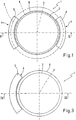
- Number 1 in Figure 1 indicates a drive device for rotating a circular horizontal table 2 about a vertical axis 3.
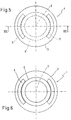
- Drive device 1 comprises a linear electric motor 4, in turn comprising an inductor or primary 5 and an armature or secondary 6; armature 6 is angularly integral with table 2 and located along at least a portion of a circumference 8 centered about axis 3; and inductor 5 is located facing armature 6 along at least a portion of a circumference 7 centered about axis 3.
- Inductor 5 may face armature 6 internally or externally, i.e. the diameter of circumference 7 may be respectively smaller or greater than circumference 8.
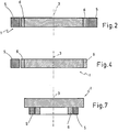
- table 2 may have a cylindrical outer periphery surrounded by armature 6, and to which the inner lateral surface of the armature is connected; or, as shown in Figures 5 and 6, armature 6 may be connected by its upper surface to the bottom of table 2; or (not shown), armature 6 may be connected by its bottom surface to the top of table 2.
- inductor 5 and armature 6 depend on different requirements.
- the angle covered by inductor 5 depends on the drive torque required - the greater the drive torque, the greater the angle covered by inductor 5 - but must be substantially no greater than the angle covered by armature 6, in that any portion of inductor 5 not facing a corresponding portion of armature 6 produces substantially no drive torque.
- the angle covered by armature 6, depends on the amount of rotation required, in that, to avoid a drastic reduction in drive torque, inductor 5 must face a corresponding portion of armature 6 throughout the movement of table 2. That is, for table 2 to make a complete turn, armature 6 must cover an angle of 360°.
- Linear electric motor 4 may be of various known types, e.g. a synchronous, asynchronous, direct-current or step motor. For machine tools, synchronous or asynchronous linear electric motors are more advantageous.
- asynchronous motors in which armature 6 is defined by a portion of the table itself. That is, as opposed to being formed separately and fixed to table 2, armature 6 is formed directly on table 2, thus obviously saving on material.
- a squirrel cage may be formed on table 2, or, in the case of low drive torques, table 2 may simply be used as it is with no special alterations.
- This type of armature 6 may, of course, only be formed if table 2 is made of steel or other material with good magnetic characteristics.
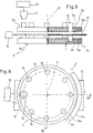
- Figure 8 shows an example of drive device 1 according to the present invention, as applied to a punching machine 9 comprising two circular horizontal tables - a top table 2a and bottom table 2b - rotating about a vertical axis 3.
- Table 2a supports a number of punches 10 arranged along a circumference 13 centered about axis 3, and table 2b supports a number of dies corresponding to and arranged similarly to punches 10.
- Machine 9 also comprises a hammer 12 moved up and down by actuating means 14, and for operating punches 10 at a predetermined work station 15; and actuating means 16 for feeding a metal work sheet 17 horizontally on to machine 9.
- Tables 2a and 2b are rotated respectively by drive devices 1a and 1b, each comprising an inductor 5, and an armature 6 connected tangentially by its lateral surface to the whole of the lateral surface of table 2.
- inductor 5 of linear electric motor 4 When supplied, inductor 5 of linear electric motor 4 generates on armature 6 a force directed tangentially with respect to the armature; and, as armature 6 is angularly integral with table 2 and located along a portion of a circumference 8 centered about the axis of rotation 3 of table 2, said force results in a drive torque for rotating table 2.
- the device according to the present invention affords numerous advantages by featuring no mechanical transmission of any sort, the driving force being generated in a part of the motor, i.e. the armature, connected directly to the table being driven. Control of the motor is extremely precise by eliminating any position errors introduced by transmission components. No maintenance is required, by virtue of the drive involving no mechanical contact. And, finally, the drive so formed is considerably more compact as compared with traditional types.
Landscapes
- Engineering & Computer Science (AREA)
- Mechanical Engineering (AREA)
- Machine Tool Units (AREA)
- Machine Tool Positioning Apparatuses (AREA)
- Linear Motors (AREA)
Applications Claiming Priority (2)
| Application Number | Priority Date | Filing Date | Title |
|---|---|---|---|
| IT96BO000153A IT1285627B1 (it) | 1996-03-20 | 1996-03-20 | Dispositivo di azionamento per la rotazione di una tavola di una macchina utensile |
| ITBO960153 | 1996-03-20 |
Publications (2)
| Publication Number | Publication Date |
|---|---|
| EP0796700A2 true EP0796700A2 (fr) | 1997-09-24 |
| EP0796700A3 EP0796700A3 (fr) | 1997-10-08 |
Family
ID=11341271
Family Applications (1)
| Application Number | Title | Priority Date | Filing Date |
|---|---|---|---|
| EP97104708A Withdrawn EP0796700A3 (fr) | 1996-03-20 | 1997-03-19 | Dispositif d'entraínement pour tourner la table d'une machine-outil |
Country Status (3)
| Country | Link |
|---|---|
| US (1) | US5924349A (fr) |
| EP (1) | EP0796700A3 (fr) |
| IT (1) | IT1285627B1 (fr) |
Cited By (3)
| Publication number | Priority date | Publication date | Assignee | Title |
|---|---|---|---|---|
| WO2000007765A3 (fr) * | 1998-08-07 | 2000-05-11 | W I T Wiemers Innovative Techn | Procede et dispositif pour l'usinage mecanique de pieces et pour le montage/demontage de modules |
| EP1155780A3 (fr) * | 2000-05-17 | 2003-11-12 | Danobat, S. Coop | Rectifieuse à broche rotative à entraínement direct |
| EP1445061A3 (fr) * | 2003-02-04 | 2004-10-27 | Weiss GmbH, Sondermaschinentechnik | Plateau tournant avec plusieurs éléments moteurs |
Families Citing this family (5)
| Publication number | Priority date | Publication date | Assignee | Title |
|---|---|---|---|---|
| US6193458B1 (en) * | 1999-04-29 | 2001-02-27 | Jeffrey D. Marsh | System for and method of binding and trimming a perfect bound book |
| US7014182B2 (en) * | 1999-04-29 | 2006-03-21 | Marsh Jeffrey D | Apparatus and method of on demand printing, binding, and trimming a perfect bound book |
| US7963733B2 (en) | 2008-10-01 | 2011-06-21 | Perfect Systems, Llc | Apparatus for and a method of binding of a perfect bound book |
| US20110044786A1 (en) * | 2009-08-18 | 2011-02-24 | Perfect Systems, Llc | Apparatus for and method of clamping and trimming a perfect bound book |
| US8739730B2 (en) * | 2009-12-17 | 2014-06-03 | Jeffrey D. Marsh | Apparatus for and a method of determining condition of hot melt adhesive for binding of a perfect bound book |
Family Cites Families (9)
| Publication number | Priority date | Publication date | Assignee | Title |
|---|---|---|---|---|
| FR2233674A1 (en) * | 1973-06-12 | 1975-01-10 | Humbert Jacques | Record player turntable drive - turntable directly driven by electric motor eliminating mechanical transmission |
| GB1482261A (en) * | 1975-06-24 | 1977-08-10 | Ideal Tubes Ltd | Storage apparatus |
| DD139331A1 (de) * | 1978-10-18 | 1979-12-19 | Eberhard Riessland | Schrittantrieb zur erzeugung einer linearbewegung eines hubtisches |
| US4343210A (en) * | 1979-05-31 | 1982-08-10 | Anritsu Electric Co Ltd | Punch press |
| IT1139107B (it) * | 1981-07-22 | 1986-09-17 | Baruffaldi Frizioni Spa | Dispositivo divisore angolare per tavola portapezzi,torretta portautensili o simili con posizionamenti non prefissati |
| JPS6048245A (ja) * | 1983-08-26 | 1985-03-15 | Hitachi Metals Ltd | インデツクステ−ブル |
| JPH01153244A (ja) * | 1987-12-08 | 1989-06-15 | Nissan Motor Co Ltd | 回転駆動台 |
| JPH02175030A (ja) * | 1988-12-27 | 1990-07-06 | Murata Mach Ltd | 回転体駆動装置における原点復帰装置 |
| US5528968A (en) * | 1994-04-14 | 1996-06-25 | Murata Machinery, Ltd. | Punch press with automated sheet rotation |
-
1996
- 1996-03-20 IT IT96BO000153A patent/IT1285627B1/it active IP Right Grant
-
1997
- 1997-03-19 EP EP97104708A patent/EP0796700A3/fr not_active Withdrawn
- 1997-03-20 US US08/821,309 patent/US5924349A/en not_active Expired - Lifetime
Cited By (6)
| Publication number | Priority date | Publication date | Assignee | Title |
|---|---|---|---|---|
| WO2000007765A3 (fr) * | 1998-08-07 | 2000-05-11 | W I T Wiemers Innovative Techn | Procede et dispositif pour l'usinage mecanique de pieces et pour le montage/demontage de modules |
| CZ298393B6 (cs) * | 1998-08-07 | 2007-09-19 | Zpusob a zarízení k mechanickému obrábení obrobkua manipulaci s montovanými ci demontovanými konstrukcními skupinami | |
| EP1155780A3 (fr) * | 2000-05-17 | 2003-11-12 | Danobat, S. Coop | Rectifieuse à broche rotative à entraínement direct |
| EP1445061A3 (fr) * | 2003-02-04 | 2004-10-27 | Weiss GmbH, Sondermaschinentechnik | Plateau tournant avec plusieurs éléments moteurs |
| US7154243B2 (en) | 2003-02-04 | 2006-12-26 | Weiss Gmbh Sondermaschinentechnik | Rotary indexing table |
| DE10304462B4 (de) * | 2003-02-04 | 2007-03-29 | Weiss Gmbh Sondermaschinentechnik | Rundschalttisch |
Also Published As
| Publication number | Publication date |
|---|---|
| IT1285627B1 (it) | 1998-06-18 |
| ITBO960153A0 (it) | 1996-03-20 |
| US5924349A (en) | 1999-07-20 |
| EP0796700A3 (fr) | 1997-10-08 |
| ITBO960153A1 (it) | 1997-09-20 |
Similar Documents
| Publication | Publication Date | Title |
|---|---|---|
| KR101887726B1 (ko) | 공작물, 특히 판금을 기계가공하기 위한 프레스 형태의 공작 기계 | |
| KR970007309B1 (ko) | 자동 공구교환 장치 | |
| EP2261017A3 (fr) | Système de commande asservie et système de travail continu de presse | |
| US5924349A (en) | Drive device for rotating a machine tool table | |
| US6125731A (en) | Feeder for an industrial machine, particularly a turret punch press, and an industrial machine utilizing the same | |
| US20080163734A1 (en) | Dividing apparatus for automatic notching presses with a direct drive | |
| KR910001813B1 (ko) | 천공기 | |
| US5813806A (en) | Hobbing machine | |
| CN109789465B (zh) | 用于加工板状工件的工具和机床以及方法 | |
| CN218633633U (zh) | 一种转定子铁芯冲片的叠装结构 | |
| WO1990006856A1 (fr) | Procede et dispositif pour faire correspondre automatiquement au moins deux surfaces essentiellement cylindriques qui entrent en contact, en particulier pour l'estampage mecanique, et plaques gravees ainsi obtenues | |
| KR100817108B1 (ko) | 금속표면 스크래칭장치 및 방법 | |
| CN111246949B (zh) | 驱动装置、用于冲口的设备及驱动用于冲口的设备的方法 | |
| US20070137433A1 (en) | Rotary indexing table driven by an induction motor | |
| CN210702712U (zh) | 一种工业自动旋转打孔装置 | |
| KR200337530Y1 (ko) | 소재가공장치 | |
| JP3690870B2 (ja) | 被加工物と加工工具との位置決め方法及び位置決め装置 | |
| CN223967777U (zh) | 一种定转子冲片机筛分装置 | |
| JP2942799B2 (ja) | 複数工程加工用工具による加工装置および加工方法 | |
| CN120696299B (zh) | 用于冲孔加工设备外壳的旋转冲孔模具及冲孔加工设备 | |
| CN2159838Y (zh) | 自动冲齿联合机 | |
| KR19990026079U (ko) | 차체 홀 가공장치 | |
| CN221790706U (zh) | 一种装备制造用冲压装置 | |
| CN216862800U (zh) | 一种柱状物料自动排序送料装置 | |
| JP2846293B2 (ja) | 加工装置 |
Legal Events
| Date | Code | Title | Description |
|---|---|---|---|
| PUAI | Public reference made under article 153(3) epc to a published international application that has entered the european phase |
Free format text: ORIGINAL CODE: 0009012 |
|
| PUAL | Search report despatched |
Free format text: ORIGINAL CODE: 0009013 |
|
| AK | Designated contracting states |
Kind code of ref document: A2 Designated state(s): AT DE ES FI FR GB IT SE |
|
| AK | Designated contracting states |
Kind code of ref document: A3 Designated state(s): AT DE ES FI FR GB IT SE |
|
| 17P | Request for examination filed |
Effective date: 19971128 |
|
| STAA | Information on the status of an ep patent application or granted ep patent |
Free format text: STATUS: THE APPLICATION IS DEEMED TO BE WITHDRAWN |
|
| 18D | Application deemed to be withdrawn |
Effective date: 19991001 |