EP0796811B1 - Dispositif pour cantres - Google Patents
Dispositif pour cantres Download PDFInfo
- Publication number
- EP0796811B1 EP0796811B1 EP97102289A EP97102289A EP0796811B1 EP 0796811 B1 EP0796811 B1 EP 0796811B1 EP 97102289 A EP97102289 A EP 97102289A EP 97102289 A EP97102289 A EP 97102289A EP 0796811 B1 EP0796811 B1 EP 0796811B1
- Authority
- EP
- European Patent Office
- Prior art keywords
- separating elements
- bobbin
- wave
- disposed
- thread
- Prior art date
- Legal status (The legal status is an assumption and is not a legal conclusion. Google has not performed a legal analysis and makes no representation as to the accuracy of the status listed.)
- Expired - Lifetime
Links
- 239000002184 metal Substances 0.000 claims description 5
- 229920003229 poly(methyl methacrylate) Polymers 0.000 claims description 2
- 239000004926 polymethyl methacrylate Substances 0.000 claims description 2
- 239000005357 flat glass Substances 0.000 claims 1
- 238000011144 upstream manufacturing Methods 0.000 claims 1
- 238000004804 winding Methods 0.000 description 16
- 230000015572 biosynthetic process Effects 0.000 description 6
- 238000005192 partition Methods 0.000 description 3
- 230000006978 adaptation Effects 0.000 description 1
- 238000005452 bending Methods 0.000 description 1
- 238000010276 construction Methods 0.000 description 1
- 238000004049 embossing Methods 0.000 description 1
- 238000004519 manufacturing process Methods 0.000 description 1
- 239000000463 material Substances 0.000 description 1
- 239000005300 metallic glass Substances 0.000 description 1
- 238000000926 separation method Methods 0.000 description 1
- 238000007493 shaping process Methods 0.000 description 1
- 230000006641 stabilisation Effects 0.000 description 1
- 238000011105 stabilization Methods 0.000 description 1
- 230000001629 suppression Effects 0.000 description 1
- 230000007704 transition Effects 0.000 description 1
Images




Classifications
-
- D—TEXTILES; PAPER
- D02—YARNS; MECHANICAL FINISHING OF YARNS OR ROPES; WARPING OR BEAMING
- D02H—WARPING, BEAMING OR LEASING
- D02H1/00—Creels, i.e. apparatus for supplying a multiplicity of individual threads
-
- B—PERFORMING OPERATIONS; TRANSPORTING
- B65—CONVEYING; PACKING; STORING; HANDLING THIN OR FILAMENTARY MATERIAL
- B65H—HANDLING THIN OR FILAMENTARY MATERIAL, e.g. SHEETS, WEBS, CABLES
- B65H57/00—Guides for filamentary materials; Supports therefor
- B65H57/22—Guides for filamentary materials; Supports therefor adapted to prevent excessive ballooning of material
-
- B—PERFORMING OPERATIONS; TRANSPORTING
- B65—CONVEYING; PACKING; STORING; HANDLING THIN OR FILAMENTARY MATERIAL
- B65H—HANDLING THIN OR FILAMENTARY MATERIAL, e.g. SHEETS, WEBS, CABLES
- B65H2701/00—Handled material; Storage means
- B65H2701/30—Handled filamentary material
- B65H2701/31—Textiles threads or artificial strands of filaments
Definitions
- the invention relates to a device on reel gates, with a limitation of thread balloons Thread take-off from bobbins in rows are arranged and those protruding into the spaces between the rows and / or in the direction of withdrawal in front of the spaces between the rows arranged separators are assigned, each extend between two rows of coils over several winding positions.
- a device with the aforementioned features is out known from DE 506 027. Between the individual rows of coils horizontal or vertical partitions are arranged, which protrude beyond the bobbin plane in the thread take-off direction. Consequently balloon formation is limited, i.e. the as a result of the overhead thread take-off rotating threads of neighboring Coils cannot beat together. It will break the thread avoided.
- the partitions used are flat Plates, the appropriate distances between adjacent Require coils.
- long drain gates result. Long drainage gates mean long thread lengths, which leads to the fact that at high yarn speeds the influences due to air friction are different. threads that run from coils at the beginning of the gate, that is, are close to the winding machine, are braked less, as threads that run from bobbins that are at the end of the gate are located. The known device is therefore for long gates not appropriate.
- the device has the advantage that it also such drain gates can be applied in which the Coil rows are offset in height.
- everyone has Bobbins equidistant from neighboring bobbins.
- the coils of a row of coils protrude into the coils of the gusset formed in adjacent rows of coils. Result it comparatively short gate lengths.
- the influence of Air friction on the threads can be minimized. It is getting less Space required for the drain gate.
- the invention is based on the object a device with the features mentioned above improve that they have offset spool drain gates Division can be applied.
- the several winding units extending separating elements in their Shaping to the winding units or to those on the winding units located coils are adapted in shape.
- the outer circumference of the coil customized balloon boundary sections are so composed that she, around the outer circumference of the coil in the area between the rows are arranged or are adjustable in this arrangement.
- the Balloon delimitation sections are therefore according to the given Intermediate rows are formed and use them such that the coils are pulled out between them or between they can be plugged in without being handicapped occur. Thread handling is also straightforward possible because of the distance between the balloon boundary sections or between the separating elements is sufficiently large. Despite their use, this also applies to spool drain gates with staggered rows, only a single separator required per row of coils.
- the device can be designed such that the dividing elements are wave-shaped rods, wherein the wavelength is equal to the pitch of the winding units is. Due to the wave-like design of the rods sufficient on the design of the spaces between rows between adjacent rows of coils taken. These distances are sufficiently large to be sufficient to be able to use thick rods, so one accordingly have sufficient rigidity. This stiffness is promoted by the wave-like shape of the rods, that the use of rods is comparatively low Diameter is made possible. The rigidity of the rod over the length seen is improved.
- the device can be improved in that the Separating elements are rotatable about a central longitudinal axis.
- the the bars forming the separating elements can easily be done by hand be twisted. Here form from the central longitudinal axis sufficient lever arms at distant shaft sections. It is easy to close the separators from one position twist in which they ensure an optimal balloon limitation, to put them in a position where they can find the optimal one Allow spool access.
- the device is designed so that the separating elements in Thread take-off direction arranged at a distance from the bobbins are.
- the distance can be dimensioned so that the radial Expansion of the thread balloon is minimized.
- the poles are easily accessible at a distance from the coil level.
- a further embodiment of the device is thereby achieved that the separating elements aligned, in the central longitudinal axis have arranged axis ends.
- the swearing Axis ends determine the axis of rotation of the separating elements or the Rods.
- the arrangement of the axle ends in the central longitudinal axis causes the same adjustments of all rod areas parallel to the coil plane.
- the invention can also be designed accordingly be that the separators in the coil area wave-like are shaped sheets, the wavelength being equal to the pitch the winding units is.
- These trained as sheets Separators are insofar as they are in the space protrude between the coil rows, the there between the Take advantage of existing coils and already there to one limit the balloon formation accordingly. Your Extension transverse to the coil plane of the gate can meet the requirements be designed according to the balloon limit.
- the sheets have the advantage that they are on the frame can be permanently installed. An adjustment for the purpose Spool change or the like. not necessary. Rather is the exchange of bobbins and the thread handling between the separating elements designed as sheets are readily possible, because the distance between two separators is the same the mean coil row width is, that is, sufficiently large is.
- the corrugated sheets are the outer circumference of the coils are comparatively narrow, it is not possible that new coils to be used in an undesirable manner fall. So the sheets have in the case of attaching new coils, which can be of considerable weight, at the same time also a stabilization or attachment aid function.
- the formation of the separating elements designed as sheet metal depends on the respective design requirements.
- the device can thus be designed, for example, that the separating elements made of sheet metal, perforated sheet metal or Acrylic glass exist.
- Both the separating elements designed as rods, as the separating elements designed as sheets can also be of this type be shaped so that the wave-shaped separating elements shaft sections parallel to the longitudinal axis, each are integrally connected by inclined sections. therefore each wave consists of six wave sections, which is one optimal adaptation of the dividing elements to the circular ones Outer circumference of the coils means, on the other hand, comparable to low deformation effort allowed to get by.
- the device can be designed, for example, that the wave-shaped separating elements from angled to the central axis arranged inclined sections. at such a formation of the separating elements can be achieved that the balloon-forming rejected by the inclined sections Thread rejected as far as possible from neighboring bobbins and the one required in the manufacture of the separating elements Deformation effort is reduced even further.
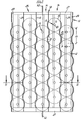
- FIG. 1 shows a rotating frame 26 in a rectangular shape, consisting of two parallel horizontal frame supports 27 and two the aforementioned at their ends together connecting parallel vertical frame beams 28. Between the horizontal supports 27 are a plurality of bobbin supports 29 arranged parallel to each other, their cross section results from Fig.2. On the cheeks of these U-shaped straps 29 coil spindles 30 are attached to both sides of the Project rotating frame 26 and one coil level on each side 31 form.
- the horizontal frame beams 27 have Pivots 32 with which the rotating frame 26 is not in one gate frame shown are pivotally arranged can, together with other rotating frames on one level.
- Several Rotating frames 26 arranged in alignment form a spool drain gate or a half of a spool drain gate.
- Everyone Swing frame is accessible from one side 33, while its other side 34 serves the thread take-off.
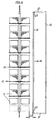
- Coils 11 are plugged onto the spool 30, what is shown schematically in FIG. 6 shows coils 11, that hang on the mandrels 30. From the coils 11 the thread F wound on this is drawn off by a winding machine, not shown, is wound up. The The withdrawal direction is symbolized by the arrow 35 in FIGS. The winding machine is roughly perpendicular to the coil plane, so that it is required with the intended overhead deduction is to redirect the thread F. This happens at the Fadenbremsund Deflection point 36, which is known for such a deflection, is not shown.
- the Spool and the braking and deflection device 36 a thread balloon 10 out of without any influence on its radial extent the maximum course 10 'indicated in FIGS. would have.
- the spool drain gate is consequently with a limitation device provided by thread balloons 10, namely with separating elements 13, which are designed in different ways.
- the coils 11 are arranged in rows one above the other. It is created side by side arranged vertical coil rows 14.
- the winding units 15 of a coil row 14 are to the winding stations 15 of the adjacent coil row 14 offset in height, namely half the pitch 20, that is, half the distance between two Coil stations 15 from each other.
- the coils 11 as tightly packed as possible.
- the extension of the bobbin drain gate in the bobbin plane is horizontal as low as possible so that the spool drain gate accordingly short.
- the coils 11 protrude at maximum Winding into the spools 11 adjacent to the gusset, however row spaces 12 remain between two neighboring ones Rows 14.
- the wave-like are shaped.
- the dividing elements consist of balloon boundary sections 17, the coil outer circumference 16 of the coils 11 are adapted. These are sheets that are sufficient are thin to be accommodated in the row spaces 12 become. Their top and bottom ends are on the horizontal Frame supports 27 attached. As a result of their wave-like Training, they are sufficiently stiff not to match the outside circumference 16 of the full coils 11 come into contact. It there is an adequate safety distance.
- Fig.2 shows that the sheet-like separating elements 13 themselves Extend over the entire coil height and slightly beyond. As a result, the thread F does not have the ability to shown balloon shape 10 'to assume.
- the wave-like design of the separating elements 13 carries to ensure that a smooth transition of the thread course from the Suppression of the balloon to free thread running in front of the deflection point 36 takes place, which reduces the frequency of thread breakage.
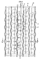
- FIG. 3 to 7 show rotating frames 26, as already described in Fig.1, so that on the new description is omitted.
- the separating elements 13 are, however, as rods formed the distance 22 to the coils 11 in the space between the rotary gate 26 and the thread braking and deflection device 36 are arranged. These separating elements 13 are also adapted to the row spaces 12.
- a separator has two rod ends 23 outside the coil area and is therefore not shown in detail Way of frame parts 37 rotatably held. Training this frame parts 37 is indicated in Figs The principle is arbitrary.
- These figures show an education a frame with frame parts 37, which are also used for mounting serve the braking and deflection device 36.
- the separating elements 13 can be rotated. You can So both take the position shown in Figure 3, like also the positions designated 13 'in FIG. It can be seen that the coils 11 between the separating elements 13th the position 13 'can be handled as previously for the Fig.1,2 has been described. In the event of a thread break So it is only necessary that the coil row with the the bobbin 11 having separating elements adjacent to the thread break 13 to pivot so that, contrary to the thread take-off direction projected over the lying between the coils 11 Row gaps 12 are arranged.
- each coil 11 between the positions 13 ' located separating elements 13 are removed, such as 7 shows in particular whose coil 11 'in diameter is smaller than the distance between the separating elements the height of the coil mandrel 15 'to which the coil 11' opposes the thread take-off direction 18 is to be attached.
- the separators 13 in to bring the position 13 ', they hinder the withdrawal of the thread F due to their arrangement or due to their partial Arrangement in front of the bobbins 11.
- the thread balloon 10 can consequently become do not train radially to the extent that it is with others Thread balloons of neighboring bobbins collided.
- This is through the shape of the separating elements 13 prevents that as well is selected as that of the separating elements 13 of Fig.1. It lies namely, a wave-like design in front of the shaft sections 24 are present, which have a central longitudinal axis 21 are parallel at a distance. This distance is the wave amplitude.
- These are parallel shaft sections 24 connected by inclined sections 25 so that each evident design from the figures.
- the shaft sections parallel to the central longitudinal axis 24 to be omitted and only inclined sections to use, which alternate at an angle to the central longitudinal axis 21 are arranged.
- the embodiments of Figures 3 to 7 are constructive extremely simple.
- the dividing elements can be made of round material can be manufactured with embossing tools. A twisting of the There are no separating bars through the striking threads F, because the rotating threads from both sides on the dividing bars incident.
Landscapes
- Engineering & Computer Science (AREA)
- Textile Engineering (AREA)
- Guides For Winding Or Rewinding, Or Guides For Filamentary Materials (AREA)
- Unwinding Of Filamentary Materials (AREA)
- Magnetic Resonance Imaging Apparatus (AREA)
- Magnetically Actuated Valves (AREA)
- Coil Winding Methods And Apparatuses (AREA)
Claims (9)
- Dispositif sur des cantres de dévidage à bobines comprenant une limitation de ballons de fils (10), le dévidage des fils étant de type aérien à partir de bobines (11) qui sont disposées en rangées et auxquelles sont attribués des éléments de séparation (13) qui sont disposés dans la zone d'espace libre ménagée entre les rangées, dans lequel ces éléments viennent s'insérer dans les espaces libres ménagés entre les rangées et/ou sont disposés dans la direction de dévidage devant les espaces libres ménagés entre les rangées, et ils s'étendent respectivement entre deux rangées de bobines (14) pardessus plusieurs têtes de bobinage (15), caractérisé en ce que les éléments de séparation (13) présentent des sections de limitations de ballons (17) qui épousent la forme d'une section de la circonférence externe des bobines, dans lequel les sections de limitations de ballons (17), dans la zone des espaces libres ménagés entre les rangées, sont disposées autour de la section de la circonférence externe des bobines et/ou sont à même de pivoter dans cet agencement.
- Dispositif selon la revendication 1, caractérisé en ce que les éléments de séparation (13) sont des barres de forme ondulée, la longueur des ondulations (19) étant égale à la distance de subdivision (20) des têtes de bobinage (15).
- Dispositif selon la revendication 2, caractérisé en ce que les éléments de séparation (13) sont aptes à tourner autour d'un axe longitudinal médian (21).
- Dispositif selon l'une quelconque des revendications 2 à 3, caractérisé en ce que les éléments de séparation (13) sont disposés, dans la direction de dévidage des fils, à une certaine distance (22) par rapport aux bobines (11).
- Dispositif selon l'une quelconque des revendications 2 à 4, caractérisé en ce que les éléments de séparation (13) présentent des extrémités d'arbres disposées à fleur dans l'axe longitudinal central (21).
- Dispositif selon la revendication 1, caractérisé en ce que les éléments de séparation (13) sont des tôles de forme ondulée dans la zone des bobines, la longueur des ondulations (19) étant égale à la distance de subdivision (20) des têtes de bobinage (15).
- Dispositif selon l'une quelconque des revendications 1 à 6, caractérisé en ce que les éléments de séparation (13) sont constitués par de la tôle, par de la tôle perforée ou par du verre acrylique.
- Dispositif selon l'une quelconque des revendications 1 à 7, caractérisé en ce que les éléments de séparation (13) sont constitués par des sections ondulées (24) parallèles à l'axe longitudinal médian, qui sont respectivement reliés en une seule pièce via des sections inclinées (25)
- Dispositif selon l'une quelconque des revendications 1 à 7, caractérisé en ce que les éléments de séparation (13) de forme ondulée sont constitués par des sections inclinées disposées en formant un angle par rapport à l'axe médian (21).
Applications Claiming Priority (2)
| Application Number | Priority Date | Filing Date | Title |
|---|---|---|---|
| DE29605326U | 1996-03-22 | ||
| DE29605326U DE29605326U1 (de) | 1996-03-22 | 1996-03-22 | Vorrichtung an Spulenablaufgattern |
Publications (3)
| Publication Number | Publication Date |
|---|---|
| EP0796811A2 EP0796811A2 (fr) | 1997-09-24 |
| EP0796811A3 EP0796811A3 (fr) | 1998-03-11 |
| EP0796811B1 true EP0796811B1 (fr) | 2002-06-19 |
Family
ID=8021505
Family Applications (1)
| Application Number | Title | Priority Date | Filing Date |
|---|---|---|---|
| EP97102289A Expired - Lifetime EP0796811B1 (fr) | 1996-03-22 | 1997-02-13 | Dispositif pour cantres |
Country Status (5)
| Country | Link |
|---|---|
| US (1) | US5806773A (fr) |
| EP (1) | EP0796811B1 (fr) |
| DE (2) | DE29605326U1 (fr) |
| ES (1) | ES2177840T3 (fr) |
| PT (1) | PT796811E (fr) |
Families Citing this family (2)
| Publication number | Priority date | Publication date | Assignee | Title |
|---|---|---|---|---|
| EP1154859B1 (fr) * | 1998-11-06 | 2008-05-07 | Interface, Inc. | Cantre compact |
| DE202005015262U1 (de) * | 2005-09-27 | 2006-11-16 | Autefa Automation Gmbh | Gatterablauf |
Family Cites Families (13)
| Publication number | Priority date | Publication date | Assignee | Title |
|---|---|---|---|---|
| US1814203A (en) * | 1928-05-28 | 1931-07-14 | Yates Henry Harrison | Creeling mechanism |
| US1872179A (en) * | 1928-06-06 | 1932-08-16 | Barber Colman Co | Warping apparatus |
| DE506027C (de) * | 1928-08-29 | 1930-08-29 | Schlafhorst & Co W | Zettelgatter |
| US2325974A (en) * | 1943-05-10 | 1943-08-03 | Peter C Pasquerello | Creel apparatus |
| CH479731A (de) * | 1967-09-06 | 1969-10-15 | Sulzer Ag | Fahrbares Spulengestell für Webmaschinen |
| GB1372010A (en) * | 1973-03-06 | 1974-10-30 | Benson A C | Warping creels |
| DE2736016C2 (de) * | 1977-08-10 | 1987-03-19 | W. Schlafhorst & Co, 4050 Mönchengladbach | Vorrichtung zum Brechen von Fadenballons |
| CH622560A5 (fr) | 1977-10-24 | 1981-04-15 | Benninger Ag Maschf | |
| US4538776A (en) * | 1984-03-14 | 1985-09-03 | West Point Foundry & Machine Co. | Creel apparatus |
| IT207416Z2 (it) * | 1986-03-28 | 1988-01-18 | Comez Spa | Struttura di cantra per il supporto di bobine di alimentazione di fili di trama e di ordito in telai tessili. |
| CH671781A5 (en) * | 1987-03-26 | 1989-09-29 | Benninger Ag Maschf | Creel ballooning limits - are on rotating rods to contain movement and give access to automatic bobbin change systems |
| CH680785A5 (fr) * | 1990-05-16 | 1992-11-13 | Benninger Ag Maschf | |
| JP2775120B2 (ja) * | 1991-03-06 | 1998-07-16 | 津田駒工業株式会社 | 巻取機などのパッケージ移送方法 |
-
1996
- 1996-03-22 DE DE29605326U patent/DE29605326U1/de not_active Expired - Lifetime
-
1997
- 1997-02-13 PT PT97102289T patent/PT796811E/pt unknown
- 1997-02-13 ES ES97102289T patent/ES2177840T3/es not_active Expired - Lifetime
- 1997-02-13 EP EP97102289A patent/EP0796811B1/fr not_active Expired - Lifetime
- 1997-02-13 DE DE59707535T patent/DE59707535D1/de not_active Expired - Fee Related
- 1997-03-21 US US08/823,062 patent/US5806773A/en not_active Expired - Fee Related
Also Published As
| Publication number | Publication date |
|---|---|
| US5806773A (en) | 1998-09-15 |
| EP0796811A2 (fr) | 1997-09-24 |
| ES2177840T3 (es) | 2002-12-16 |
| EP0796811A3 (fr) | 1998-03-11 |
| PT796811E (pt) | 2002-11-29 |
| DE59707535D1 (de) | 2002-07-25 |
| DE29605326U1 (de) | 1997-07-24 |
Similar Documents
| Publication | Publication Date | Title |
|---|---|---|
| DE2813011C3 (de) | Feststehende elektrische induktionsvorrichtung | |
| EP0796811A2 (fr) | Dispositif pour cantres | |
| DE2628812A1 (de) | Verfahren zum wickeln einer rohrwendel und anordnung zur durchfuehrung des verfahrens | |
| DE2220228B2 (de) | Spinn- oder zwirnmaschine | |
| DE60213702T2 (de) | Garnaufwickelhülse | |
| DE2918387C2 (fr) | ||
| EP1747609B1 (fr) | Transmetteur rotatif pour des raccords de cable | |
| DE8411285U1 (de) | Wickeltraeger | |
| DE68904185T2 (de) | Maschine zur herstellung von kablierten zwirnen. | |
| DE2952400A1 (de) | Verfahren und vorrichtung zum aufspulen einer vielzahl von faeden | |
| DE10343315A1 (de) | Vorrichtung zum Aufspulen eines Fadens auf eine Kreuzspule | |
| DE3817678C1 (en) | Cabling machine for double twisting - has supporting cross wall on machine frame after every second spindle | |
| EP0534896B1 (fr) | Dispositif et procédé pour limiter le ballon sur un cantre | |
| DE102016014977A1 (de) | Aufspulmaschine | |
| DE29706686U1 (de) | Raffvorhang mit einer Wickelspule | |
| EP0638506B1 (fr) | Frein à disques pour fils textiles | |
| EP1918434B1 (fr) | Ourdissoir d'échantillonnage | |
| DE3904261C2 (fr) | ||
| DE3835503C2 (fr) | ||
| CH680785A5 (fr) | ||
| DE19945823C1 (de) | Aufspulmaschine | |
| CH646211A5 (de) | Spulengatter fuer zettelmaschinen. | |
| DE941052C (de) | Spulengatter zur Aufnahme von haengend angeordneten Ablaufspulen fuer Spinnereimaschinen | |
| DE2058333A1 (de) | Spulengatter fuer Ringspinnmaschinen | |
| DE2736016C2 (de) | Vorrichtung zum Brechen von Fadenballons |
Legal Events
| Date | Code | Title | Description |
|---|---|---|---|
| PUAI | Public reference made under article 153(3) epc to a published international application that has entered the european phase |
Free format text: ORIGINAL CODE: 0009012 |
|
| AK | Designated contracting states |
Kind code of ref document: A2 Designated state(s): BE CH DE ES FR IT LI PT |
|
| PUAL | Search report despatched |
Free format text: ORIGINAL CODE: 0009013 |
|
| AK | Designated contracting states |
Kind code of ref document: A3 Designated state(s): BE CH DE ES FR IT LI PT |
|
| 17P | Request for examination filed |
Effective date: 19980512 |
|
| 17Q | First examination report despatched |
Effective date: 20000414 |
|
| GRAG | Despatch of communication of intention to grant |
Free format text: ORIGINAL CODE: EPIDOS AGRA |
|
| GRAG | Despatch of communication of intention to grant |
Free format text: ORIGINAL CODE: EPIDOS AGRA |
|
| GRAH | Despatch of communication of intention to grant a patent |
Free format text: ORIGINAL CODE: EPIDOS IGRA |
|
| GRAH | Despatch of communication of intention to grant a patent |
Free format text: ORIGINAL CODE: EPIDOS IGRA |
|
| GRAA | (expected) grant |
Free format text: ORIGINAL CODE: 0009210 |
|
| RAP1 | Party data changed (applicant data changed or rights of an application transferred) |
Owner name: SUCKER-MUELLER-HACOBA GMBH & CO. |
|
| AK | Designated contracting states |
Kind code of ref document: B1 Designated state(s): BE CH DE ES FR IT LI PT |
|
| REG | Reference to a national code |
Ref country code: CH Ref legal event code: EP |
|
| REF | Corresponds to: |
Ref document number: 59707535 Country of ref document: DE Date of ref document: 20020725 |
|
| REG | Reference to a national code |
Ref country code: CH Ref legal event code: NV Representative=s name: E. BLUM & CO. PATENTANWAELTE |
|
| ET | Fr: translation filed | ||
| REG | Reference to a national code |
Ref country code: PT Ref legal event code: SC4A Free format text: AVAILABILITY OF NATIONAL TRANSLATION Effective date: 20020912 |
|
| REG | Reference to a national code |
Ref country code: ES Ref legal event code: FG2A Ref document number: 2177840 Country of ref document: ES Kind code of ref document: T3 |
|
| PLBE | No opposition filed within time limit |
Free format text: ORIGINAL CODE: 0009261 |
|
| STAA | Information on the status of an ep patent application or granted ep patent |
Free format text: STATUS: NO OPPOSITION FILED WITHIN TIME LIMIT |
|
| 26N | No opposition filed |
Effective date: 20030320 |
|
| REG | Reference to a national code |
Ref country code: CH Ref legal event code: PUE Owner name: MOENUS TEXTILMASCHINEN GMBH Free format text: SUCKER-MUELLER-HACOBA GMBH & CO.#BLUMENBERGER STRASSE 143-145#41061 MOENCHENGLADBACH (DE) -TRANSFER TO- MOENUS TEXTILMASCHINEN GMBH#HEINRICH-HERTZ-STRASSE 28#07552 GERA (DE) |
|
| PGFP | Annual fee paid to national office [announced via postgrant information from national office to epo] |
Ref country code: PT Payment date: 20060201 Year of fee payment: 10 |
|
| PGFP | Annual fee paid to national office [announced via postgrant information from national office to epo] |
Ref country code: BE Payment date: 20060202 Year of fee payment: 10 |
|
| PGFP | Annual fee paid to national office [announced via postgrant information from national office to epo] |
Ref country code: ES Payment date: 20060209 Year of fee payment: 10 |
|
| PGFP | Annual fee paid to national office [announced via postgrant information from national office to epo] |
Ref country code: FR Payment date: 20060301 Year of fee payment: 10 |
|
| PG25 | Lapsed in a contracting state [announced via postgrant information from national office to epo] |
Ref country code: PT Free format text: LAPSE BECAUSE OF NON-PAYMENT OF DUE FEES Effective date: 20070813 |
|
| REG | Reference to a national code |
Ref country code: PT Ref legal event code: MM4A Free format text: LAPSE DUE TO NON-PAYMENT OF FEES Effective date: 20070813 |
|
| REG | Reference to a national code |
Ref country code: CH Ref legal event code: PFA Owner name: MOENUS TEXTILMASCHINEN GMBH Free format text: MOENUS TEXTILMASCHINEN GMBH#HEINRICH-HERTZ-STRASSE 28#07552 GERA (DE) -TRANSFER TO- MOENUS TEXTILMASCHINEN GMBH#HEINRICH-HERTZ-STRASSE 28#07552 GERA (DE) |
|
| REG | Reference to a national code |
Ref country code: FR Ref legal event code: ST Effective date: 20071030 |
|
| BERE | Be: lapsed |
Owner name: *SUCKER-MULLER-HACOBA G.M.B.H. & CO. Effective date: 20070228 |
|
| PG25 | Lapsed in a contracting state [announced via postgrant information from national office to epo] |
Ref country code: BE Free format text: LAPSE BECAUSE OF NON-PAYMENT OF DUE FEES Effective date: 20070228 |
|
| PG25 | Lapsed in a contracting state [announced via postgrant information from national office to epo] |
Ref country code: FR Free format text: LAPSE BECAUSE OF NON-PAYMENT OF DUE FEES Effective date: 20070228 |
|
| REG | Reference to a national code |
Ref country code: ES Ref legal event code: FD2A Effective date: 20070214 |
|
| PG25 | Lapsed in a contracting state [announced via postgrant information from national office to epo] |
Ref country code: ES Free format text: LAPSE BECAUSE OF NON-PAYMENT OF DUE FEES Effective date: 20070214 |
|
| REG | Reference to a national code |
Ref country code: CH Ref legal event code: PUE Owner name: SUCKER TEXTILMASCHINEN GMBH Free format text: TEXMAG-ABWICKLUNGSGESELLSCHAFT MBH#HEINRICH-HERTZ-STRASSE 28#07552 GERA (DE) -TRANSFER TO- SUCKER TEXTILMASCHINEN GMBH#BLUMENBERGER STRASSE 143-145#41061 MOENCHENGLADBACH (DE) Ref country code: CH Ref legal event code: PFA Owner name: TEXMAG-ABWICKLUNGSGESELLSCHAFT MBH Free format text: MOENUS TEXTILMASCHINEN GMBH#HEINRICH-HERTZ-STRASSE 28#07552 GERA (DE) -TRANSFER TO- TEXMAG-ABWICKLUNGSGESELLSCHAFT MBH#HEINRICH-HERTZ-STRASSE 28#07552 GERA (DE) |
|
| PGFP | Annual fee paid to national office [announced via postgrant information from national office to epo] |
Ref country code: DE Payment date: 20090217 Year of fee payment: 13 |
|
| PGFP | Annual fee paid to national office [announced via postgrant information from national office to epo] |
Ref country code: CH Payment date: 20090223 Year of fee payment: 13 |
|
| PGFP | Annual fee paid to national office [announced via postgrant information from national office to epo] |
Ref country code: IT Payment date: 20090227 Year of fee payment: 13 |
|
| REG | Reference to a national code |
Ref country code: CH Ref legal event code: PL |
|
| PG25 | Lapsed in a contracting state [announced via postgrant information from national office to epo] |
Ref country code: LI Free format text: LAPSE BECAUSE OF NON-PAYMENT OF DUE FEES Effective date: 20100228 Ref country code: CH Free format text: LAPSE BECAUSE OF NON-PAYMENT OF DUE FEES Effective date: 20100228 |
|
| PG25 | Lapsed in a contracting state [announced via postgrant information from national office to epo] |
Ref country code: DE Free format text: LAPSE BECAUSE OF NON-PAYMENT OF DUE FEES Effective date: 20100901 |
|
| PG25 | Lapsed in a contracting state [announced via postgrant information from national office to epo] |
Ref country code: IT Free format text: LAPSE BECAUSE OF NON-PAYMENT OF DUE FEES Effective date: 20100213 |